Week -2
1. SIMULINK MODEL FOR DOORBELL USING SOLENOID:
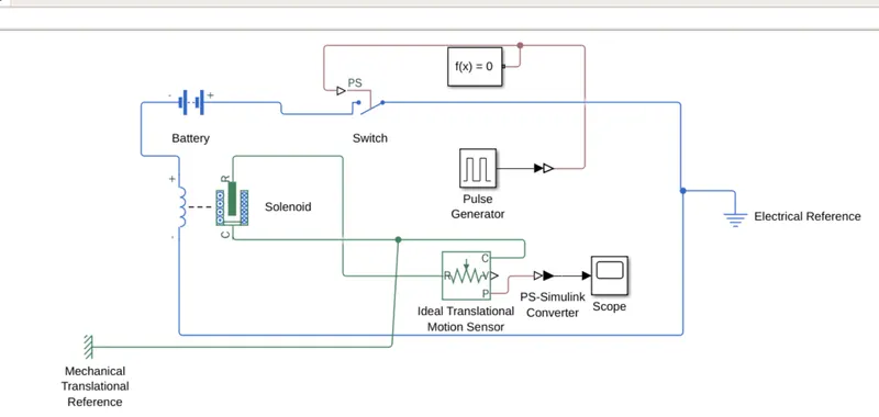
Simulink model explaination-
1. pulse genearator
2. switch
3. battery
3. solenoid.
4. ideal translational motion sesor
5. mechanical translational referance
6. electrical referance
7. scope
8. simulink to ps converter
As per given conditions switch is closed for 2 sec & then released.
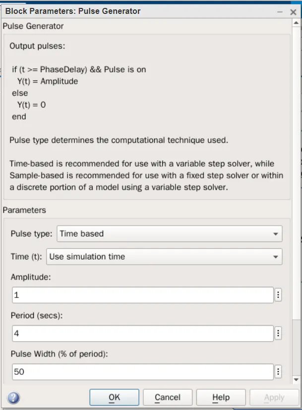
The pulse genearator is used to create square wave at regular intervals.The block waveform parameters,amplitude ,pulsewidth ,phase delay deterrmines the sshape of the waveforms.
switch block is controlled by the physical signal & if the physical signal is greater then switch is closed or else switch is open positive terminal is connected with the block while as the negative terminal is connected to the electrical referance when we connect solenoid block with the switch and battery we form a complete circuit.
the port c is connected to mechanical referrance . ideal translational motion sesor is connected to the r port of the solenoid to observe the movement of plunger. scope is connected to the ideal translational motion sensor to get the output.
a signal from pulse genearator is converted using simulink to ps converter is given to the input switch
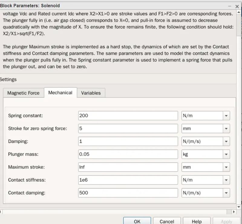
A solenoid introduced battery is connected to it the voltage of battery connected was made same as that of rated voltage of the solenoid .switch is also connected to the same circuit.
the position of the plunger is connected to the ideal translational motion sesor . the initial position of the plunger is set to 5 mm in the transalational motion sensor . the scope is connected to visualize the behaviour of the plunger
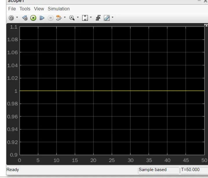
the simulation is run for the 20 sec.
PULSE GRNEARATOR:
SOLENOID
SIMULINK MODEL FOR DOORBELL USING SOLENOID:
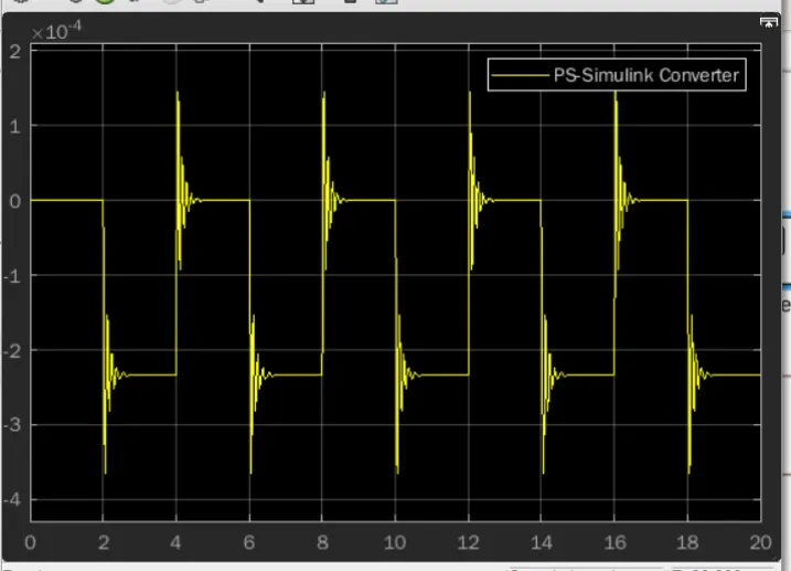
RESULT:
CONCLUSION:-
Giving input as timr perod of 2 sec in the pulse genearator to open and close the switch .
when switch is clossed solenoid recieves electric poewer from the battery and plunger moves from port r to port c to hit the bell and produce sound
physical movement of the plunger obsorved by translational motion sensor .
2. Use a thermistor to sense the temperature of a heater & turn on or turn off the fan as per the below conditions
THERMISTOR:-
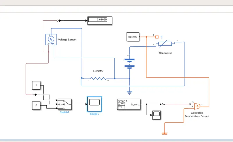
It is device which is used to sense the temparature differance in the heat flow. its working based on the relationship between the tempearature and the resistance. in this model positive temperature coefficient thermistor is used . so here resistance increases or decreases with respect to the temperature. the output of thermister is in the form of voltage and current . increase in voltage or current indicates increase in temperature
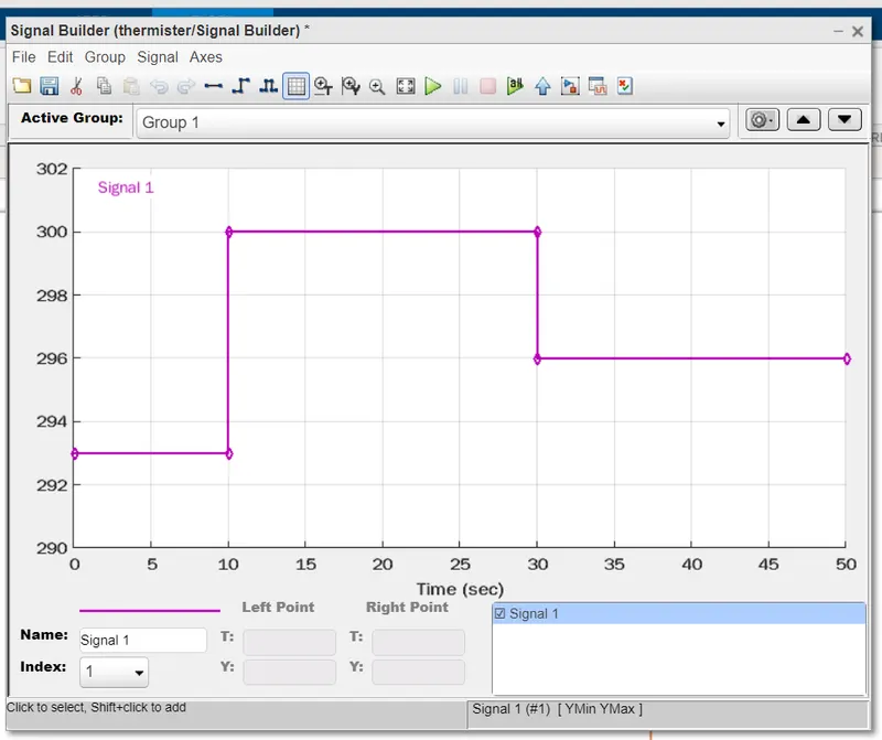
in this model signal builder is used to get tempearature signal for the controlled temp source (heater).
temperature of the heater is supplied to the thermister to sens it. if temperature of the heater is reches the value 298 K the we have to trigger the exernal battery supply . resistor also connected in the series . voltage sensor is connected across the resistor to calculate the voltage drop and voltage drop is inputed as threshold value to switch the fan and fan will go on when threshold value is more than 0
INPUT SIGNAL:-
MODEL:-
OUTPUT:-