Week 7 - Simulation of a 1D Super-sonic nozzle flow simulation using Macormack Method
Objective :
To simulate the isentropic flow through a quasi 1D subsonic-supersonic nozzle by deriving both conservative and non conservative forms of governing equation and solve them by using Macormack Method in matlab.
Problem statement :
- Need to determine the steady-state temperature distribution for the flow-field variables and to investigate the difference between the two forms of governing equations by comparing their solutions.
- To plot steady-state distribution of primitive variables inside the nozzle.
- To plot time-wise variation of the primitive variables.
- To plot variation of Mass flow rate distribution inside the nozzle at different time steps during the time-marching process.
- To plot comparison of Normalized mass flow rate distributions of both forms.
Theory :
Mach number :
It is a dimensionless quantity representing the ratio of flow velocity to the local speed of the sound.
M=uc
M - Mach number.
u - Flow velocity.
c - Velocity of sound.
Nozzle diagram :
The nozzle has three main sections
1. convergent.
2. Throat.
3. Divergent
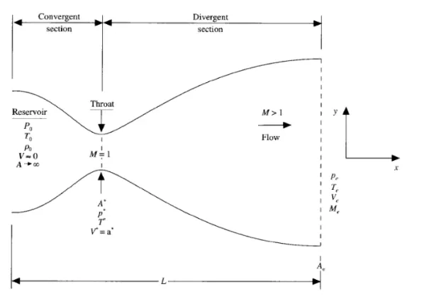
- At convergent section the flow velocity is less than the sound velocity therefore there mach number is less than 1.
- At throat section the flow velocity is equal to the sound velocity therefore there mach number is equal to 1.
- At divergent section the flow velocity is greater than the sound velocity therefore there mach number is greater than 1.
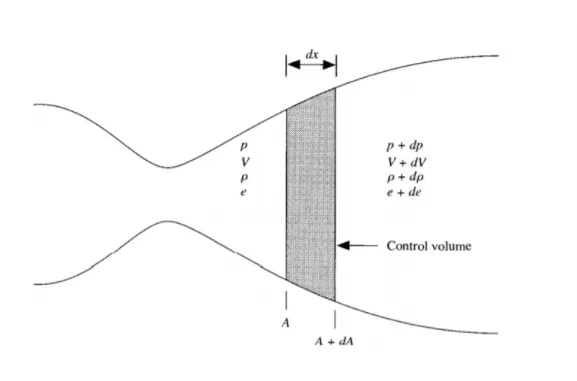
So here, the flow at the inlet of the nozzle comes from a reservoir where pressure and temperature are denoted as byρ0 and T0 respectively. The cross sectional area of the reservoir is large (theoretically, A→∞) and hence the velocity is very small (V→0). Thus, ρ0 and T0 are the stagnation values or total pressure and temperature respectively. The flow expands isentropically to supersonic speeds at the nozzle exits, where the exit pressure, temperature, velocity, and Mach number are denoted by Pe, Te, Ve and Me respectively. The flow is locally subsonic in the convergent section, sonic at the throat section and supersonic at the divergent section. The sonic flow (M=1) at the throat means that the local velocity at this location is equal to the local speed of sound. Using an asterisk to denote sonic flow values, we have at the throat V = V* = a* Similarly, the sonic flow values of pressure and temperature are denoted by P* and T*, respectively.
Although the area of nozzle changes as a function of distance along the nozzle x and therefore in reality the flow field is two dimensional (xy), we make an assumption that the flow properties vary only with x, this tendency to assume uniform flow properties across any given cross-section. Such flow is defined as Quasi-one-dimensional flow.
In order to solve quasi-one-dimensional problem, we need PDE or Integral form of equations for CFD analysis. These PDE or Integral form of the governing equations are in both conservative and non-conservative form.
Before, writing the governing equations in conservative and non-conservaticve form, we need to non-dimensionalize the primitive variables for removing the constraints of dimensions to analyse the numerical solution. It will certainly ease the method of analysis for a given problem.
Non Dimensional Quantities :
Also as part of the problem setup we represent quantities in terms of non-dimensional quantities
Temperature T'=TT0
Density ρ'=ρρ0
Non - dimensional distance X'=XL
Non dimensional velocity V'=Va0 where as a0 is the local sonic velocity (a0=√γRT0)
Non-dimensional time t'=t(La0) where La0 is characteristic time scale.
Non dimensional area A'=AA∗
∂(ρ'A'V')∂t'+∂(ρ'A'(V')2)+1γ(p'A')∂x'=1γp'(∂A')∂x'
Energy equation :
∂ρ'(T'γ−1+γ2(V')2)A'∂t'+∂(ρ'(T'γ−1+γ2(V')2)A'V'+p'A'V')∂x'=0
The above is the generic form of non-dimensional conservation form of the continuity, momentum and energy equations for quasi-one-dimensional flow. Let us define the above equations in a simple generic form, which will be used in calculations instead of the above rigid and complex form. Elements of the solutions vector U, the flux vector F, and the source term J as follows,
U1=ρ'A'
U2=ρ'A'V'
U3=ρ'(T'γ−1+γ2(V')2)A'
F1=ρ'A'V'
F2=ρ'A'(V')2+1γp'A'
F3=ρ'(T'γ−1+γ2(V')2)A'V'+p'A'V'
J2=1γp'∂A'∂x'
Before setting up numerical solution for conservative form, we must keep in mind that in the conservation form of the governing equations, the dependent variables (the variables for which we directly obtain numbers) are not primitive variables. In order to calculate the primitive variables, we need to decode the dependent variables and update our primitive variables in further steps.
Non Conservative form :
MacCormack method :
MacCormack's method is an explicit finite-difference technique which is second order accurate in both space and time. MacCormack method generally uses three step approach(Predictor, Corrector and averaging) to calculate a final numerical solution for an iteration. In predictor step, forward difference is taken for spatial derivatives whereas in corrector step, rearward (backward) difference is taken for spatial derivatives. Furthermore, the solutions obtained from these two steps are averaged and final numerical solution is calculated for a single iteration.
Initial and boundary conditions :
To start the time-marching calculations, we must stipulate initial conditions for ρ, T and V as a function of x; that is, we must set up values of ρ, T and V at time t = 0.
Non-conservative form :
Initial conditions :
ρ=1−0.3146x
T=1−0.2314x
V=(0.1+1.09x).T12
Boundary conditions :
In our case, we are having a subsonic flow in the convergent section (M<1), choked flow at the throat section (M=1) and supersonic outflow in the divergent section (M>1). So by using method of characteristics for an unsteady, one-dimensional flow we can precisely allot inflow and outflow boundary conditions and can identify which quantities to state at the boundaries.
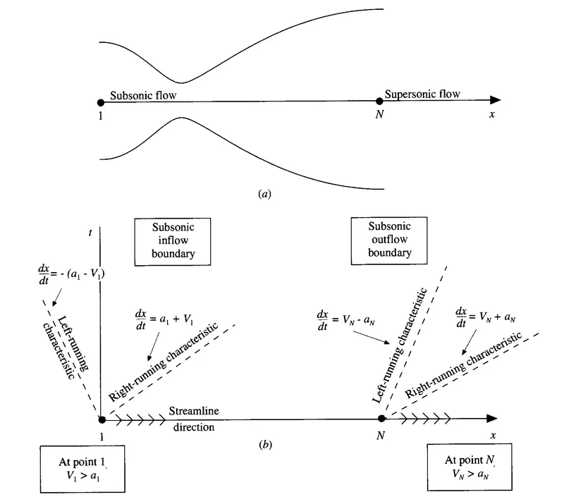
Fig (b) : Study of boundary conditions: subsonic inflow and supersonic outflow
What does these characteristics curve and streamline direction tells us?
- If any characteristic line is entering into the domain, implies that the value of one dependent flow field variable must be specified at that boundary.
- However, if any characteristic line is exiting the domain, implies that the value of the another dependent flow field variable must be allowed to float at that boundary i.e. it must be calculated in steps of time as function time wise solution of the flow field.
- Similarly, if streamline flows into the domain then specify third dependent flow field variable and if streamline flows out of the domain then third dependent flow field variable must be allowed to float.
In our case, at i = 1(inlet), we have primitive varibles like ρ, A, V and T. So which variables must be taken for initial and boundary conditions? Here, we know the ρ and T at node 1 are equal to the reservoir's ρ and T which is assumed to be ρ=1 and T=1, so it becomes,
Inflow boundary condition :
ρ(1)=1and T(1) =1(Since it is Dirichlet boundary condition)
However, velocity and area tends to infinity, so for velocity, we need to calculate it from the information obtained from inner nodes,
V(1)=2⋅V(2)-V(3)">V(1) = 2V(2) - V(3) (It is Neumann boundary condition)
Outflow boundary condition :
At the outflow boundary condition (Node =n), as we can see that, both the characteristics lines are out of the domain and streamline also flows out of the domain. This is because, at the outflow condition, the flow is supersonic (M>1), which is certainly greater than the speed of sound. So in this condition, information transport is very fast. Therefore, there are no flow field variables which require their values to be stipulated at the supersonic outflow boundary; all variables must be allowed to float at this boundary.
ρ(n) = 2ρ(n-1) - ρ(n-2)
V(n) = 2V(n-1) - V(n-2)
T(n) = 2T(n-1) - T(n-2)
The supersonic outflow boundary is purely Neumann boundary condition, which is extrapolating the boundary nodes using the information from inner nodes.
Conservative form :
In conservative form, we will initialize the nozzle profile rationally. As in conservative form, seen above from the governing equations, we have solution vectors, flux terms and a source term. So it is the prior matter of concern to state initial and boundary conditions in those terms rather than that of primitive variables.
Initial conditions :
These variations are slightly more realistic than those assumed in the nozzle shape and initial conditions in non-conservative form of governing equations discussed above. This is an anticipation that the stability behaviour of the finite-difference formulation using the conservation form of the governing equations might be slightly more sensitive, and therefore it is useful to start with more improved initial conditions than those discussed above in non-conservative form.
Assumptions for initial profile of the nozzle :
- For 0≤x'≤0.5
ρ' = 1
T' = 1
- For 0.5≤x'≤1.5
ρ' = 1.0 - 0.366(x'-0.5)
T' = 1.0 - 0.167(x'-0.5)
- For 0.5≤x'≤1.5
ρ' = 0.634 - 0.3879(x'-1.5)
T' = 0.833 - 0.3507(x'-1.5)
Before stating the initial conditions in terms of solution vectors, we need to initialize velocity(V'). We have one of the dependent variable in our governing equation as U2, which is physically local mass flow; that is U2=ρ'A'V'. Therefore, for the initial conditions only; let us assume a constant mass flow through the nozzle and calculate V' as,
V' = U2ρ'A'= 0.59ρ'A'
Note: The value 0.59 is chosen for U2, because it is close to exact analytical value of the steady-state mass flow (which is for this case is 0.579)
Therefore, the initial condition for V' as a function of x' is obtained by substituting the ρ′">`rho'` and A' variation. Finally, the initial conditions for U1,U2 and U3 are obtained by substituting the above variations for ρ' T' and V' into the definitions discusssed above.
U1=ρ'A'
U2=ρ'A'V'
U3=ρ'(e'γ−1+γ2(V')2)A'
where, e' = T'. Certainly, for the initial conditions described above, V' is calculated such that U2=ρ'A'V' = 0.59
Boundary conditions :
In conservative form, by referring fig (b) and absorbing the same method of characteristics approach we can allot boundary conditions for inflow and outflow boundary conditions. However, in this case, the boundary conditions will be in terms of solution vectors. Similarly as discussed above, at the subsonic inflow (M<1), we need to specify two quantities at the initial node, where we have ρ',A' and U2=ρ'A'V' = 0.59(Mass flow rate) specified and one quantity will be allowed to float by referring left hand characteristic line. However, at the supersonic outflow (M>1), the information is travelling exceeds the speed of sound, hence it is irrational to specify outflow boundary condition. Therefore, all the dependent variables are allowed to float and they will be calculated in steps of time as a function time-wise solution of the flow field.
Inflow boundary condition :
The inflow boundary condition can be given as,
U1=ρ'(1)A'(1) (Dirichlet boundary condition)
U2=2.U2(2)−U2(3)
V(1)=U2(1)U1(1)
Note: This velocity at the first node will be substituted below in calculating U3
U3=U1(1)'(T'(1)γ−1+γ2(V'(1))2) (Neumann boundary condition)
Outflow boundary condition :
All the dependent variables will be allowed to float. Hence, the outflow boundary can be given as,
U1(n)=2U1(n−1)−U1(n−2) (Neumann boundary condition)
U2(n)=2U2(n−1)−U2(n−2) (Neumann boundary condition)
U3(n)=2U3(n−1)−U3(n−2) (Neumann boundary condition)
Time step calculation :
The governing system of equations is hyperbolic with respect to time. So there is stability constraint on this system which is known as Courant-Friedrich-Lewy (CFL) condition. The Courant number is a simple stability analysis of a linear hyperbolic equations that gives result CFL≤1 for an explicit numerical solution to be stable.
CFL condition can be given as,
CFL condition = (any quantity)*(time-step with which information would travel)/(element step size)
So, in our case, the quantity which is going to travel is velocity, or in other sense velocity is the quantity which will be travelling with certain time from one node to other. So here velocity of the fluid at a point in the flow is coupled with local speed of sound. The quantity can be expressed to be as a+v'
CFL = ("a + v').(Δt)/(Δx)
We will assume the Courant number as C = 0.5, accordingly will calculate the Δt. In addition to it, we will calculate (Δt)ti
at all the grid points, i = 1 to i = n, and then we'll choose the minimum value of Δt in our calculations.
After considering all these governing equations and their respective pre-requisites to solve the problem, then we will move towards to the MATLAB code for execution.
Program :
Main program :
clear all
close all
clc

% solving Quasi 1-D super sonic nozzle flow equations
% In put parameter
% No. of grid points
n=31;

gamma = 1.4
x=linspace(0,3,n);
dx = x(2)-x(1);

% No. of timeste
nt = 1400
% courant number
c = 0.5;

% function for non conservative form
tic;
[mass_flow_rate_nc, pressure_nc, mach_number_nc, rho, v, t, rho_throat_nc, v_throat_nc, temp_throat_nc, mass_flow_rate_throat_nc, pressure_throat_nc, mach_number_throat_nc] = non_conservative_form(x,dx,n,gamma,nt,c);
time = toc;
fprintf('Simulation time for non conservative form = %0.4f',time);
hold on

% plotting
% Timestep variation of properties at the throat area in non conservative
% form

figure(2)

%Density
subplot(4,1,1)
plot(rho_throat_nc,'color','r')
ylabel('Density')
legend({'Density at throat'});
axis([0 1400 0 max(rho_throat_nc)]);
grid minor;
title('Variation of field variables with respect to time step at throat area for non-conservative form')

% Temperature
subplot(4,1,2)
plot(temp_throat_nc,'color','c')
ylabel('Temperature')
legend({'Temperature at throat'});
axis([0 1400 0.6 max(temp_throat_nc)]);
grid minor;


% Pressure
subplot(4,1,3)
plot(pressure_throat_nc,'color','c')
ylabel('pressure')
legend({'pressure at throat'});
axis([0 1400 0.4 max(pressure_throat_nc)]);
grid minor;


% Mach number
subplot(4,1,4)
plot(mach_number_throat_nc,'color','r')
xlabel('Timesteps')
ylabel('pressure')
legend({'Mach number at throat'});
axis([0 1400 0.6 max(mach_number_throat_nc)]);
grid minor;


% Steady state simulation for primitive values for non conservative form
figure(3);

%Density

subplot(4,1,1)
plot(x,rho,'color','m')
ylabel('Densty')
legend({'Density'});
axis([0 3 0 max(rho)])
grid minor;
title('Variation of field variable along the length of nozzle for non-conservative form')

% Temperature
subplot(4,1,2)
plot(x,t,'color','c')
ylabel('Temperature')
legend({'Temperature'});
axis([0 3 0 max(t)])
grid minor;

% pressure
subplot(4,1,3)
plot(x,pressure_nc,'color','g')
ylabel('pressure')
legend({'pressure'});
axis([0 3 0 max(pressure_nc)])
grid minor;

% Mach number
subplot(4,1,4)
plot(x,mach_number_nc,'color','y')
ylabel('Mach Number')
legend({'Mach Number'});
axis([0 3 0 max(mach_number_nc)])
grid minor;

% function for conservative form
tic;
[mass_flow_rate_c, pressure_c, mach_number_c, rho_c, v_c, temp_c, rho_throat_c, v_throat_c, temp_throat_c, mass_flow_rate_throat_c, pressure_throat_c, mach_number_throat_c] = conservative_form(x,dx,n,gamma,nt,c);
time = toc;
fprintf('Simulation time for conservative form = %0.4f',time);
hold on

% plotting
% Timestep variation of properties at the throat area in conservative form

figure(5)

% Density
subplot(4,1,1)
plot(rho_throat_c,'color','m')
ylabel('Density')
legend({'Density at throat'});
axis([0 1400 0.5 max(rho_throat_c)]);
grid minor;
title('Variation of field variables with respect to time step at throat area for conservative form')

% Temperature
subplot(4,1,2)
plot(temp_throat_c,'color','c')
ylabel('Temperature')
legend({'Temperature at throat'});
axis([0 1400 0.8 max(temp_throat_c)]);
grid minor;


% Pressure
subplot(4,1,3)
plot(pressure_throat_c,'color','g')
ylabel('pressure')
legend({'pressure at throat'});
axis([0 1400 0.4 max(pressure_throat_c)]);
grid minor;

% Mach number
subplot(4,1,4)
plot(mach_number_throat_c,'color','y')
xlabel('Timesteps')
ylabel('Mach number')
legend({'Mach number at throat'});
axis([0 1400 0.9 max(mach_number_throat_c)]);
grid minor;

% Steady state simulation for primitive values for non conservative form
figure(6);

% Density
subplot(4,1,1)
plot(x,rho_c,'color','m')
ylabel('Density')
legend({'Density'});
axis([0 3 0 max(rho_c)])
grid minor;
title('Variation of flow rate distribution - conservative form')

% Temperature
subplot(4,1,2)
plot(x,temp_c,'color','c')
ylabel('Temperature')
legend({'Temperature'});
axis([0 3 0 max(temp_c)])
grid minor;

% pressure
subplot(4,1,3)
plot(x,pressure_c,'color','g')
ylabel('pressure')
legend({'pressure'});
axis([0 3 0 max(pressure_c)])
grid minor;

% Mach number
subplot(4,1,4)
plot(x,mach_number_c,'color','y')
xlabel('Nozzle length')
ylabel('Mach Number')
legend({'Mach Number'});
axis([0 3 0 max(mach_number_c)])
grid minor;

% Comparison plot of normalized mass flow rate of both forms
figure(7)
hold on
plot(x,mass_flow_rate_nc,'r','linewidth',1.25)
hold on
plot(x,mass_flow_rate_c,'b','linewidth',1.25)
hold on
grid on

legend('Non-conservative','Conservative');
xlabel('length of domain')
ylabel('mass flow rate')
title('Comparison of normalized mass flowrate of both forms')
Sub program :
Conservative form :
% Conservative form

function [mass_flow_rate_c, pressure_c, mach_number_c, rho_c, v_c, temp_c, rho_throat_c, v_throat_c, temp_throat_c, mass_flow_rate_throat_c, pressure_throat_c, mach_number_throat_c] = conservative_form(x,dx,n,gamma,nt,c)

% Determining initial profile of density or temperature
for i=1:n

    if (x(i) >=0 && x(i) <=0.5)
        rho_c(i) = 1;
        temp_c(i) = 1;
    elseif (x(i) >=0.5 && x(i) <= 1.5)
        rho_c(i) = 1-0.366*(x(i)-0.5);
        temp_c(i) = 1 - 0.167*(x(i)-0.5);
    elseif (x(i) >=1.5 && x(i) <= 3)
        rho_c(i) = 0.634-0.3879*(x(i)-1.5);
        temp_c(i) = 0.833 - 0.3507*(x(i)-1.5);
    end
end


a = 1+2.2*(x-1.5).^2;
throat = find(a==1);

% Calculate initial profiles
v_c = 0.59./(rho_c.*a);
pressure_c = rho_c.*temp_c;

%Calculate the initial solution vectors(U)
U1 = rho_c.*a;
U2 = U1.*v_c;
U3 = U1.*((temp_c./(gamma-1))+(gamma/2).*(v_c.^2));

% Outer time loop
for k =1:nt
    % Time-step control
    dt = min(c.*dx./(sqrt(temp_c) + v_c));
%     Dt = temp_c.^0.5;
%     dt = min(c*(dx./(Dt + v_c)));


    %saving a copy of old values
    U1_old = U1;
    U2_old = U2;
    U3_old = U3;

    %Calculating the flux vector(F)
    F1 = U2;
    F21 = (U2.^2)./(U1);
    F22 = (gamma-1)/(gamma);
    F23 = U3 - ((gamma/2).*F21);
    F2 = F21 + F22 * F23;


    F31 = (U2.*U3)./(U1);
    F32 = (gamma*(gamma-1))/2;
    F33 = (U2.^3)./(U1.^2);
    F3 = gamma.*F31 - (F32.*F33);


    % predictor method
    for j= 2:n-1

        % Calculating the source term(J)
        J2_P(j) = (1/gamma)*(rho_c(j)*temp_c(j))*((a(j+1)-a(j))/dx);

        % continuity equation
        dU1_dt_P(j) = -((F1(j+1)- F1(j))/dx);

        % Momentum equation
        dU2_dt_P(j) = -((F2(j+1)- F2(j))/dx)+J2_P(j);

        % Energy Equation
        dU3_dt_P(j) = -((F3(j+1) - F3(j))/dx);


        % Updating new values
        U1(j) = U1(j)+ dU1_dt_P(j)*dt;
        U2(j) = U2(j)+ dU2_dt_P(j)*dt;
        U3(j) = U3(j)+ dU3_dt_P(j)*dt;

    end

    % Updating flux vectors
    rho_c =  U1./a;
    v_c = U2./U1;
    temp_c = (gamma-1)*((U3./U1 - (gamma/2)*(v_c).^2));

     %Calculating the flux vector(F)
    F1 = U2;
    F21 = (U2.^2)./(U1);
    F22 = (gamma-1)/(gamma);
    F23 = U3 - ((gamma/2).*F21);
    F2 = F21 + F22 * F23;


    F31 = (U2.*U3)./(U1);
    F32 = (gamma*(gamma-1))/2;
    F33 = (U2.^3)./(U1.^2);
    F3 = gamma.*F31 - (F32.*F33);


    %corrector Method
    for j = 2:n-1

        % updating the source term(J)
        J2(j) = (1/gamma)*rho_c(j)*temp_c(j)*((a(j)-a(j-1))/dx);

        %Simplifying the Equation's spatial terms
        dU1_dt_C(j) = -((F1(j)-F1(j-1))/dx);
        dU2_dt_C(j) = -((F2(j)-F2(j-1))/dx)+J2(j);
        dU3_dt_C(j) = -((F3(j)-F3(j-1))/dx);
    end

    % Compute Average time derivative
    dU1_dt = 0.5*( dU1_dt_P +  dU1_dt_C);
    dU2_dt = 0.5*( dU2_dt_P +  dU2_dt_C);
    dU3_dt = 0.5*( dU3_dt_P +  dU3_dt_C);

    % Final solution update
    for i = 2:n-1
        U1(i) = U1_old(i) + dU1_dt(i)*dt;
        U2(i) = U2_old(i) + dU2_dt(i)*dt;
        U3(i) = U3_old(i) + dU3_dt(i)*dt;
    end

    % Applying Boundary conditions
    % At Inlet
    U1(1) = rho_c(1)*a(1);
    U2(1) = 2*U2(2)-U2(3);

    v_c(1) = U2(1)./U1(1);
    U3(1) = U1(1)*((temp_c(1)/(gamma-1))+((gamma/2)*(v_c(1)).^2));

    % At Outlet
    U1(n) = 2*U1(n-1)-U1(n-2);
    U2(n) = 2*U2(n-1)-U2(n-2);
    U3(n) = 2*U3(n-1)-U3(n-2);
    % Final primitive value update
    rho_c =  U1./a;
    v_c = U2./U1;
    temp_c = (gamma-1)*((U3./U1 - (gamma/2)*(v_c).^2));

    % Defining Mass flow rate, pressure and Mach number

    mass_flow_rate_c = rho_c.*a.*v_c;
    pressure_c = rho_c.*temp_c;
    mach_number_c = (v_c./sqrt(temp_c));

    % Calculating Variables at throat section
    rho_throat_c(k) = rho_c(throat);
    temp_throat_c(k) = temp_c(throat);
    v_throat_c(k) = v_c(throat);
    mass_flow_rate_throat_c(k) = mass_flow_rate_c(throat);
    pressure_throat_c(k) = pressure_c(throat);
    mach_number_throat_c(k) = mach_number_c(throat);

    % plotting
    % comparison of non-dimensional mass flow rates at diferent time
    % steps

    figure(8)
    if k==50
        plot(x, mass_flow_rate_c,'m','linewidth',1.25);
        hold on
    elseif k == 100
        plot(x, mass_flow_rate_c,'c','linewidth',1.25);
        hold on
    elseif k == 200
        plot(x, mass_flow_rate_c,'g','linewidth',1.25);
        hold on
    elseif k == 400
        plot(x, mass_flow_rate_c,'y','linewidth',1.25);
        hold on
    elseif k == 800
        plot(x, mass_flow_rate_c,'k','linewidth',1.25);
       hold on
    end

    % Labelling
    title('Mass flow rates at different timesteps - conservative form')
    xlabel('Distance')
    ylabel('Mass flow rate')
    legend({'50th Timestep','100th Timestep','200th Timestep','400th Timestep','800th Timestep'})
    axis([0 3 0.4 1])
    grid on

    end
end
Non-conservative form :
function [mass_flow_rate_nc, pressure_nc, mach_number_nc, rho, v, t, rho_throat_nc, v_throat_nc, temp_throat_nc, mass_flow_rate_throat_nc, pressure_throat_nc, mach_number_throat_nc] = non_conservative_form(x,dx,n,gamma,nt,c);

% Calculate initial profiles
rho = 1-0.3146*x;
t = 1-0.2314*x;              % t is a temperature
v = (0.1+1.09*x).*t.^(1/2);

% Area
a = 1+2.2*(x-1.5).^2;
throat = find(a==1)

% outer time loop
for k=1:nt

    %Time step control
    dt = min(c.*dx./(sqrt(t) + v));

    % Saving a copy of old values
    rho_old = rho;
    v_old = v;
    t_old = t;

    % predictor method
    for j = 2:n-1
        dvdx = (v(j+1)-v(j))/(dx);
        drhodx = (rho(j+1)-rho(j))/(dx);
        dtdx = (t(j+1)-t(j))/(dx);
        dlogadx = (log(a(j+1))-log(a(j)))/(dx);

        %continuity equation
        drhodt_p(j) = -rho(j)*dvdx - rho(j)*v(j)*dlogadx-v(j)*drhodx;

        %momentum equation
        dvdt_p(j) = -v(j)*dvdx - (1/gamma)*(dtdx+(t(j)/rho(j))*drhodx);

        % Energy equation
        dtdt_p(j) = -v(j)*dtdx -(gamma-1)*t(j)*(dvdx + v(j)*dlogadx);

        %solution update
        rho(j) = rho(j)+drhodt_p(j)*dt;
        v(j) = v(j)+dvdt_p(j)*dt;
        t(j) = t(j)+dtdt_p(j)*dt;
    end

     % corrector method
    for j = 2:n-1
        dvdx = (v(j)-v(j-1))/(dx);
        drhodx = (rho(j)-rho(j-1))/(dx);
        dtdx = (t(j)-t(j-1))/(dx);
        dlogadx = (log(a(j))-log(a(j-1)))/(dx);

        %continuity equation
        drhodt_c(j) = -rho(j)*dvdx - rho(j)*v(j)*dlogadx-v(j)*drhodx;

        %momentum equation
        dvdt_c(j) = -v(j)*dvdx - (1/gamma)*(dtdx+(t(j)/rho(j))*drhodx);

        % Energy equation
        dtdt_c(j) = -v(j)*dtdx -(gamma-1)*t(j)*(dvdx + v(j)*dlogadx);

    end

    % compute the average time derivation
    drhodt = 0.5*(drhodt_p + drhodt_c);
    dvdt = 0.5*(dvdt_p + dvdt_c);
    dtdt = 0.5*(dtdt_p + dtdt_c);

    % Final solution update
    for i=2:n-1
       v(i) = v_old(i) +dvdt(i)*dt;
       rho(i) = rho_old(i) +drhodt(i)*dt;
       t(i) = t_old(i)+dtdt(i)*dt;
    end

    %Apply boundary conditions
    % Inlet
    v(1) = 2*v(2) - v(3);

    %Outlet
    v(n) = 2*v(n-1)- v(n-2);
    rho(n) = 2*rho(n-1)- rho(n-2);
    t(n) = 2*t(n-1)- t(n-2);


    % Defining Mass flow rate, pressure and Mach number

    mass_flow_rate_nc = rho.*a.*v;
    pressure_nc = rho.*t;
    mach_number_nc = (v./sqrt(t));

    % Calculating Variables at throat section
    rho_throat_nc(k) = rho(throat);
    temp_throat_nc(k) = t(throat);
    v_throat_nc(k) = v(throat);
    mass_flow_rate_throat_nc(k) = mass_flow_rate_nc(throat);
    pressure_throat_nc(k) = pressure_nc(throat);
    mach_number_throat_nc(k) = mach_number_nc(throat);

    % plotting
    % comparison of non-dimensional mass flow rates at diferent time
    % steps

    figure(4)
    if k==50
        plot(x, mass_flow_rate_nc,'m','linewidth',1.25);
        hold on
    elseif k == 100
        plot(x, mass_flow_rate_nc,'c','linewidth',1.25);
        hold on
    elseif k == 200
        plot(x, mass_flow_rate_nc,'g','linewidth',1.25);
        hold on
    elseif k == 400
        plot(x, mass_flow_rate_nc,'y','linewidth',1.25);
        hold on
    elseif k == 800
        plot(x, mass_flow_rate_nc,'k','linewidth',1.25);
        hold on
    end

    % Labelling
    title('Mass flow rates at different timesteps - non-conservative form')
    xlabel('Distance')
    ylabel('Mass flow rate')
    legend({'50th Timestep','100th Timestep','200th Timestep','400th Timestep','800th Timestep'})
    axis([0 3 0 2])
    grid on

end
Output :
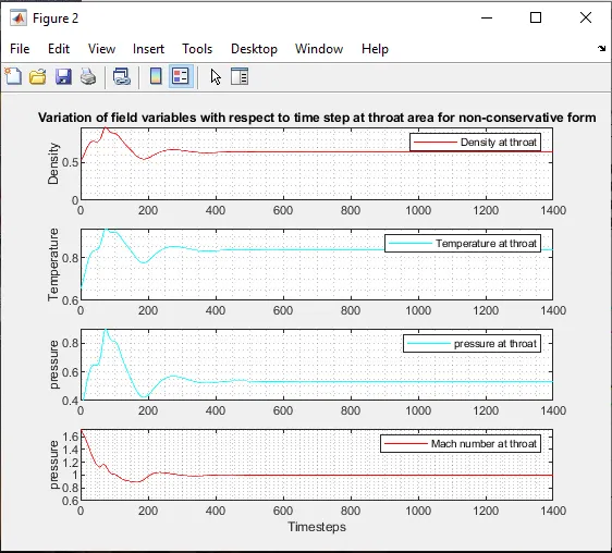
The variation of flow field variables at throat section with respect to time step for non-conservative form as shown above. From the graph it is clear that the flow field variables are almost reached the steady state solution after the 400th iteration.
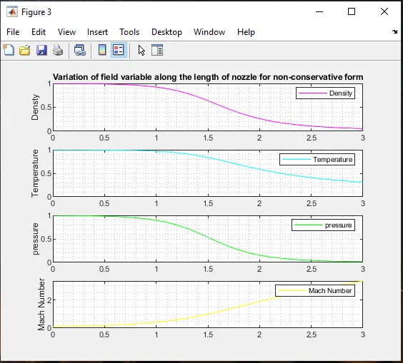
The above graph shows that the variation of flow field varialbles along the length of the nozzle for the non conservative form. In the above graph it is clear that the flow field variables such as density, pressure, temperature decreases and mach number increases with a increase in length of the nozzle.
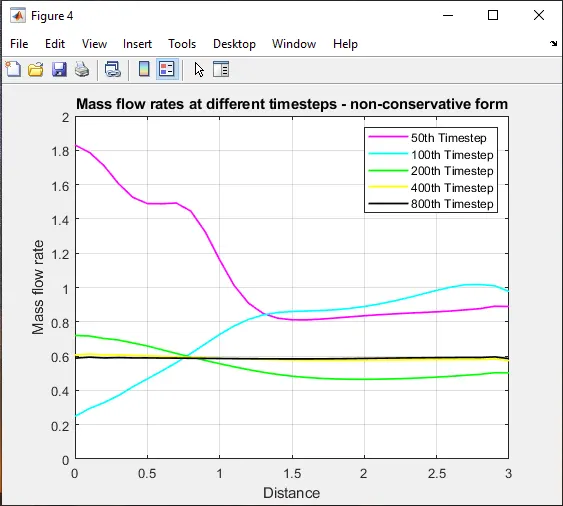
The above figure shows that the variation of mass flow rate with respect to time step for non-conservation form. From the graph it is clear that the mass flow rate is almost stable after the 400th time step.
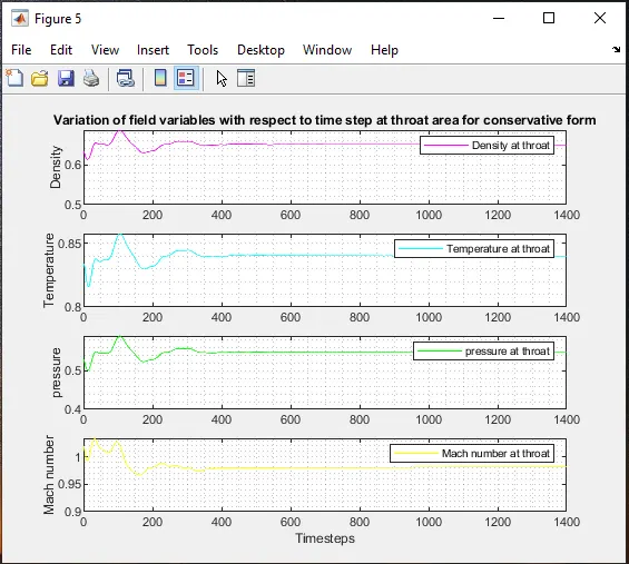
The variation of flow field variables at throat section with respect to time step for conservative form as shown above. From the graph it is clear that the flow field variables are almost reached the steady state solution after the 400th iteration.
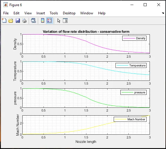
The above graph shows that the variation of flow field varialbles along the length of the nozzle for the conservative form. In the above graph it is clear that the flow field variables such as density, pressure, temperature decreases and mach number increases with a increase in length of the nozzle.
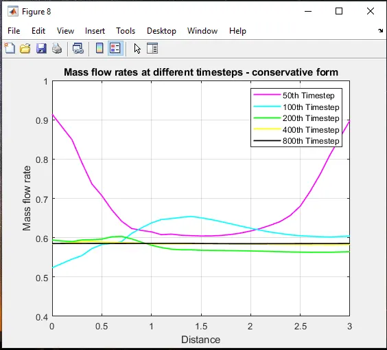
The above figure shows that the variation of mass flow rate with respect to time step for conservation form. From the graph it is clear that the mass flow rate is almost stable after the 400th time step.
Normalized mass flow rate distributions of both forms :
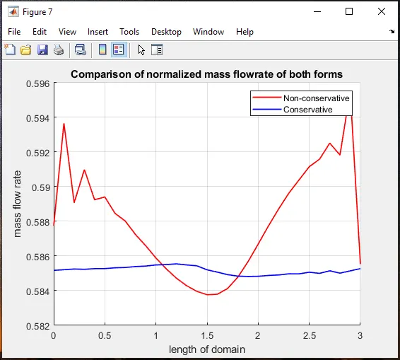
The above figure shows that the variation of mass flow rate at the both the forms. From the graph it is clear that the mass flow rate of conservative forms produces a stable result when compare to that of non conservative form. We can also find that the mass flow rate is minimum at the throat then it expands in the non conservative form. From figure the average mass flow rate of conservative form is 0.585
Grid dependence test :
In order to conduct grid dependency test for the flow field variables at the throat setion at the end of 1400th time step the solutions at two conditions need to be considered one with 31 grid points and the other with 61 grid points.
| GRID DEPENDENCE TEST | |||||
| Type of Form | No. of Grids(n) | Primitive variables | |||
| Density | Pressure | Temperature | Mach Number | ||
| Non Conservative from | 31 | 0.6387 | 0.5342 | 0.8365 | 0.9994 |
| 61 | 0.6376 | 0.5326 | 0.8354 | 0.9997 | |
| Conservative form | 31 | 0.6504 | 0.5463 | 0.8400 | 0.9818 |
| 61 | 0.6383 | 0.5330 | 0.8351 | 0.9993 | |
| Expected output | 0.634 | 0.528 | 0.833 | 1 | |
From the table it is clear that the solution of 61 grid points almost equal to the exact solution when compare to that of the solution of 31 grid points. More the number of grid points more will the computational time but at the same time we can able to produce the accurate result than the lesser grid point.
Conclusion :
Simulation of isentropic flow through a quasi 1D subsonic-supersonic nozzle by deriving both conservative and non conservative forms of governing equation and solve them by using Macormack Method in matlab is successfully compiled and the results are discussed at the output. Between conservative and non-conservative forms, In order to get a smooth solution conservative form is preferred because non-conservative form may leads to shocks at the shock flow region.