Week 7: Shock tube simulation project
AIM
* To setup a transient shock tube simulaton.
* To plot the temperature andd pressure history on entire domain.
* To Plot the cell count as a function of time.
INTRODUCTION
A shock tube is a instrument used to replicate and direct blast wave to a sensor or a model in order to simulate actual explosion and its effect. Shock tubes are used to study or simulate compressible flow as well as to simulate gas based combustion simulation. Recently shock tubes are used in biomedical research to study the effect of blast waves on. The shock tube geometry is a simple one it consists of a rectangular or circular tube, divided into two region namley a high pressure region and a low pressure region. High pressure region will be filled with a gas at high pressure similarly low pressure region will be filled with gas at low pressure, these two regions will be separated by a diaphragm.
Working of shock tube is that the pressure inside the high pressure chamber (region) builds up which causes the diaphragm to break and a shock wave propagates through the low pressure gas. The generated shock waves hit the walls at end of low pressure chamber and reflects back and hits the wall on high pressure side.
As stated above shock tube can be used to simulate gas based combustion reaction and hence the ignition delay can be calculated. The setup for the same is like on the low pressure side the combustion gas is stored and on the high pressure side O2 is stored at high pressure. As the pressure increases on high pressure side the O2 breaks open the diaphragm and flows into the low pressure combustion gases, when this happen the combustion takes place, but there will be a lag from the breaking of diaphragm to the ignition to happen this is called ignition delay. When the high pressure gas breaks into low pressure region the temperature also increases, and at a particular temperature auto ignition happens and hence combustion takes place, so the time taken to reach the auto ignition temperature is nothing but ignition delay.
In this simulation the geometry used is of rectangular type, N2 and O2 are the gases used on high pressure and low pressure side respectivley. Complete simulation setup is discussed below,
SIMULATIONS
Geometry :
The geometry used for the simulation is a square prism or in other words a rectangular block. Geometry along with its dimension is as shown below,
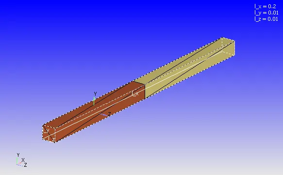
For this geometry when diagnosis is carried out it shows Non-manifold error, because at the interface of 2 regions common edge is being shared between triangles, this error can't be rectified manually but it is auto corrected by the converge-studio itself once we complete the entire setup. The rectangular block colored dark brown (on the left hand side) is set to be the high pressure side and the other half is set to be low pressure side.
* Case setup :
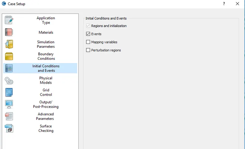
* Application type is set as time based simulation along with it under the initial condition local control under the application tab the events is checked. Events are necessary replicating the breakage of diaphragm. A snip of the application window with events checked is shown below,
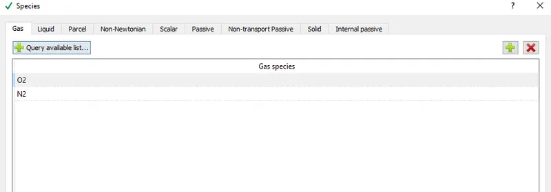
* Under materials tab the simulation is set as gas simulation and air is selected as the fluid, also the reaction mechanism is unchecked and species is checked. Gas simulation and global transport parameters are set at default values. Under the species tab, O2 and N2 are added as the species.
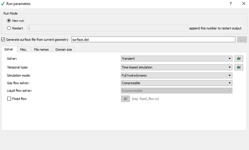
* Run parameters are set as transient state solver, gas solver is set as compressible solver and full hydrodynamic simulation is set.
* Since the run parameter is set as transient simulation time parameters are set in seconds. Start time is set as zero and end time is set at 0.003 sec, also initial time step is set as 1e-09 so is the minimum time step. Max time step is set as 1 and max CFL number is also set as 1.
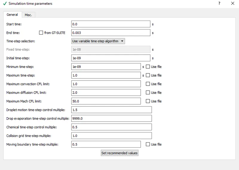
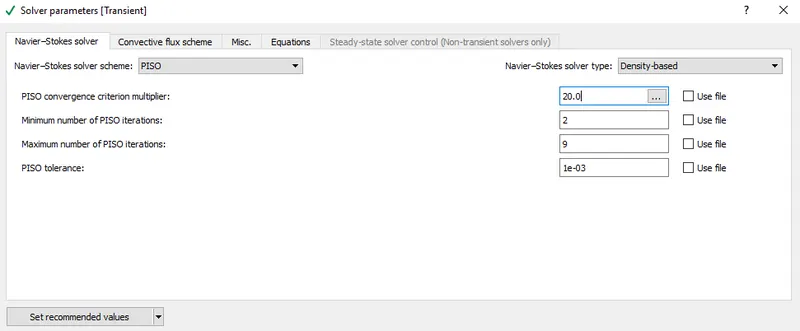
* Under solver parameters the Navier stokes solver is set as density solver and under the equations local control max iteration for the pressure is set as 5000 iterations to be on safer side. other local controls under the solver parameters tab is left as default.
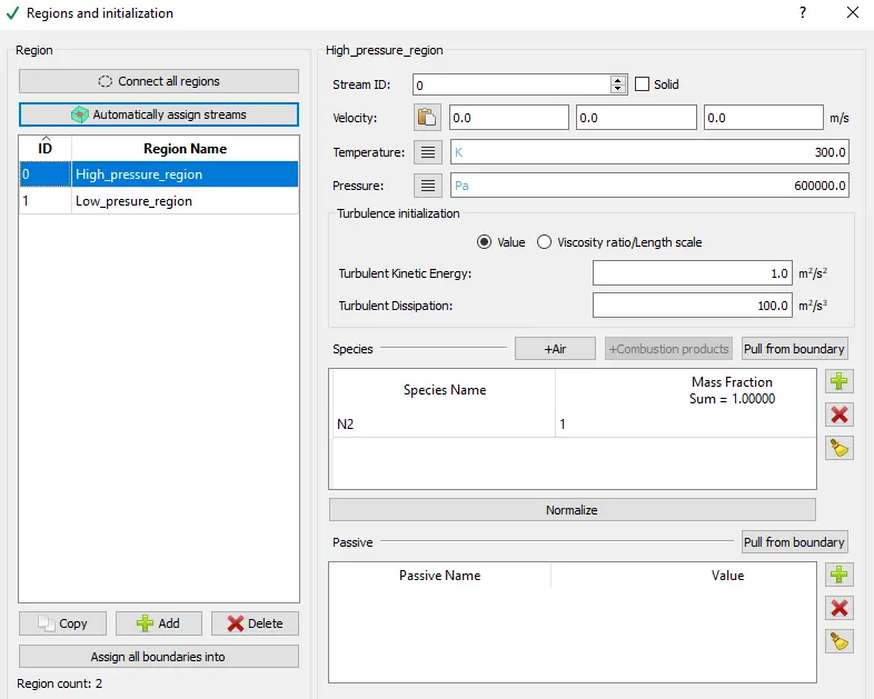
* Before proceeding with setting up the boundary condition initial conditions are set. Under the regions and initialisation tab at first a high pressure region is defined for which the initial temperature is set as 300 K and pressure is set at 600000 Pa. N2 is the species assigned for this region. A snip of the high pressure region along with the above disscussed parametre is shown below,
* A low pressure region is also defined where the temperature is set as 300K and pressure is set as 101325 Pa. O2 is the species assigned to this region.
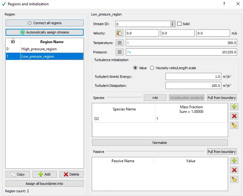
* So from the above initialization it is clear that it is the high pressure N2 which will be expanding into the low pressure O2 region.
* Since initialization is done now the boundary conditions are set. Only 2 boundary regions are created and they are flagged as H_p and L_p, a snip of the same along with its id is shown below,
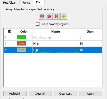
* For both H_p and L_p boundary type is set as wall, wall motion type is set as stationary, surface movement is set as fixed along with slip condition. Also boundary H_p is assigned to High_pressure_region and boundary L_p is assigned to Low_pressure_region.
* Once this much of setup is completed, now the events is set. As mentioned in the introductory part in an actual shock tube there will be a diaphragm which separates high pressure region from low pressure region, so as simulate the same in a simulation events are set. Also under the applications tab we can find the event option, which needs to checked before so that it becomes visible under the initial conditions and events tab.
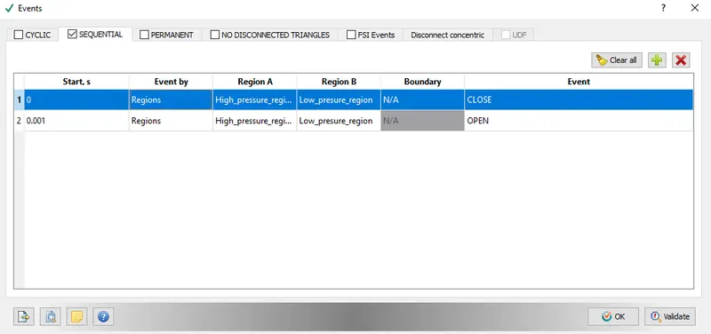
* There are many ways through which we can set the event. Cyclic, sequential, permanent, no disconnected triangles, FSI events and disconnect concentrix are the different ways in which the event can be set. For this simulation sequential is the way used under which we set the time till which the N2 pressure build up is restricted only to high pressure region (i.e time till which the diaphragm is not broken). Start time is set at zero second at which both the high pressure region and low pressure region are closed and one more time step is added, 0.001 sec at which both the regions are open. So till 0.001 sec the diaphragm is not burst. A snip of the same is shown below which will make things even more clear,
* Turbulence model used is RNG K-ε and all other local controls under the physical model tab is left default.
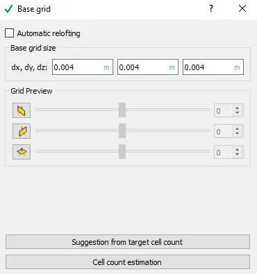
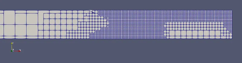
* A grid size of 0.004 m is used to which adaptive mesh refinement is applied.
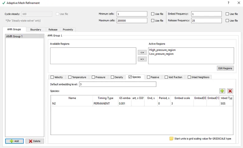
* Under adaptive mesh refinement local controls max cell count is set to 200000. Species is the criteria used for the refinement of the cell. Both high pressure region and low pressure region are set active for the refinements. N2 is the species on which sub grid criteria is set. A snip of the same is provided below,
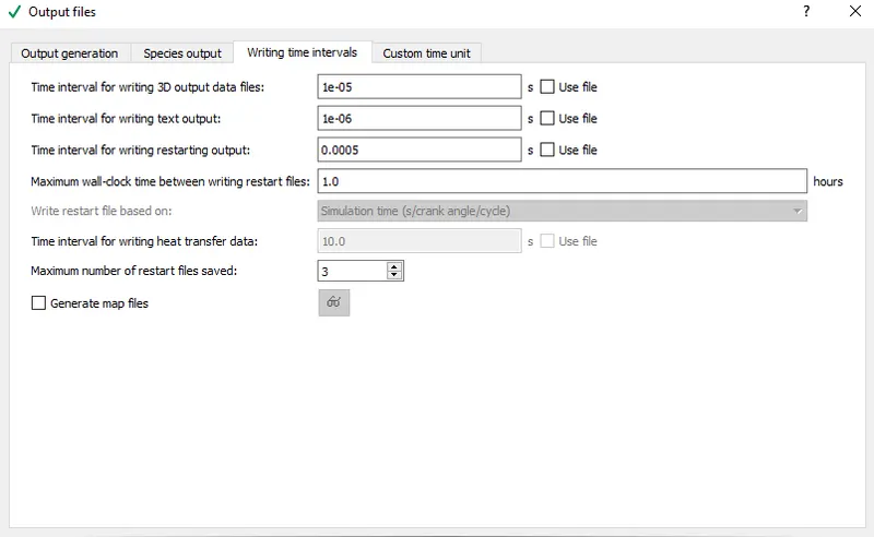
* Under output files local control time interval for writing 3D output files is set to 1e-05 sec. Time interval for writing text output is set as 1e-06 sec and Time interval for starting restart output is set at 0.0005 sec.
* Simulation is run for base grid of 0.004 m and results are noted.
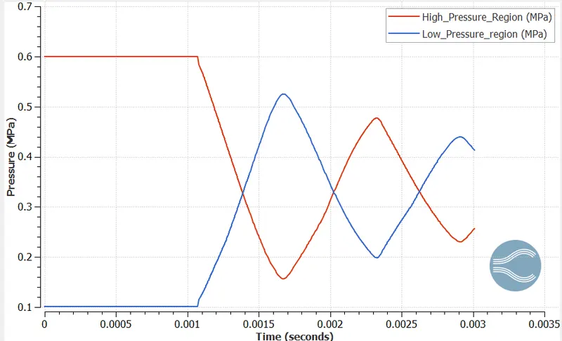
* Pressure plot on entire domain:
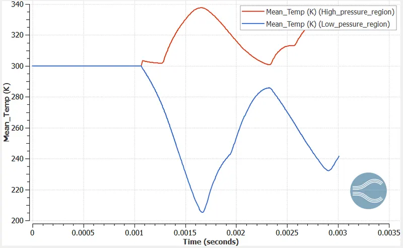
* Temperature plot on entire domain:
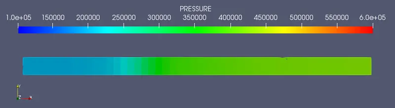
* Pressure contour:
* Pressure change animation: https://youtu.be/C7hsSB4WVMo
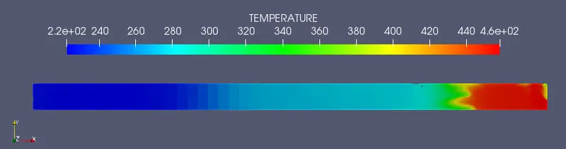
* Temperature contour:
* Meshed surface:

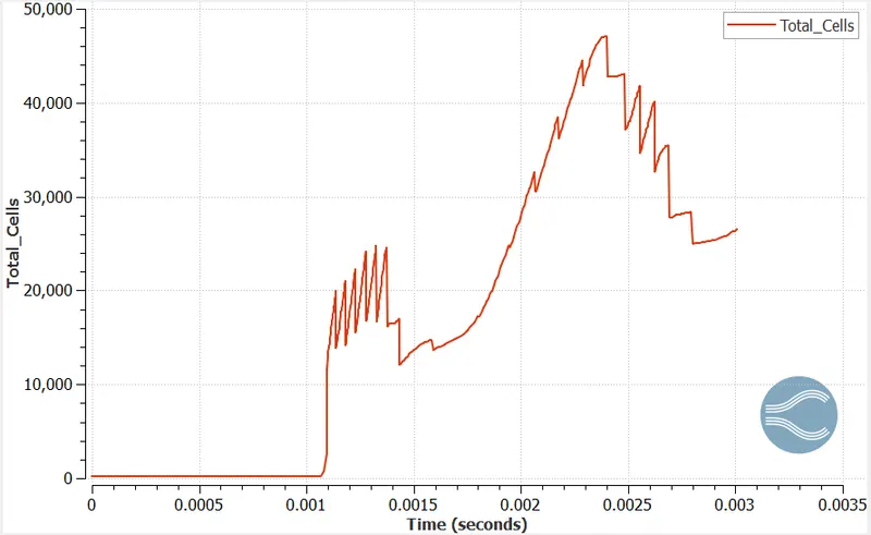
* Cell count plot:
CONCLUSION
* From the pressure contour it can be concluded that high pressure N2 has created the shock and hence it has replaced O2 from low pressure region. Also there has been a too and fro motion of the shock waves generated because of which when the simulation stopped at 0.003 sec the pressure of N2 is low compared to the initial pressure. This can be validated by observing the pressure profile.
* Because of the high pressure generated by N2 and resulting shock waves temperature of N2 has increased from initial value of 300 K to a max temerature of around 460 K.
* AMR has worked well in capturing the shock wave that too at low pressure side, max cell count achieved is around 0.0025 sec that too close to 50000 cells.