Week 7 - Minor Project
. Aim: 2D CFD analysis of flow over an airfoil using Converge CFD.
II. Problem Statement: Perform 2D transient analysis of flow over an airfoil at different angle of attacks. The case setup is done using ConvergeCFD and simulation is run in the CYGWIN terminal. Further, post-processing is done using Converge CFD and ParaView. The main objective of this project is to check the effect of the turbulence model and different angle of attacks on the lift and drag coefficients using ConvergeCFD.
III Objectives:
Simulate flow over a 4 digit airfoil i.e NACA 2412 Airfoil. and calculate the following,
- Drag co-efficient Vs Angle of Attack
- Lift co-efficient vs Angle of Attack
- Compare the effect of turbulence models on the above two results.
- The inlet Reynolds number is should be 200,000
- Perform above calculations for the following angle of attacks,
- Angle of attack = 5º
- Angle of attack = 10º
- Angle of attack = 15º
IV: Introduction:
An airfoil or aerofoil is the cross-sectional shape of an object whose motion through a fluid is capable of generating significant lift, such as a wing, a sail, or the blades of a propeller, rotor, or turbine.
A solid body moving through a fluid produces an aerodynamic force. The component of this force perpendicular to the relative freestream velocity is called lift. The component parallel to the relative freestream velocity is called drag. An airfoil is a streamlined shape that is capable of generating significantly more lift than drag[1]. Airfoils designed for use at different speeds differ in their geometry: those for subsonic flight generally have a rounded leading edge, while those designed for supersonic flight tend to be slimmer with a sharp leading edge. All have a sharp trailing edge. Foils of similar function designed with water as the working fluid are called hydrofoils.
The lift on an airfoil is primarily the result of its angle of attack. When oriented at a suitable angle, the airfoil deflects the oncoming air (for fixed-wing aircraft, a downward force), resulting in a force on the airfoil in the direction opposite to the deflection. This force is known as aerodynamic force and can be resolved into two components: lift and drag. Most foil shapes require a positive angle of attack to generate lift, but cambered airfoils can generate lift at zero angle of attack[1]. This "turning" of the air in the vicinity of the airfoil creates curved streamlines, resulting in lower pressure on one side and higher pressure on the other. This pressure difference is accompanied by a velocity difference, via Bernoulli's principle, so the resulting flowfield about the airfoil has a higher average velocity on the upper surface than on the lower surface.
Airfoil design is a major facet of aerodynamics. Various airfoils serve different flight regimes. Asymmetric airfoils can generate lift at zero angle of attack, while symmetric airfoil may better suit frequent inverted flight as in an aerobatic airplane. In the region of the ailerons and near a wingtip a symmetric airfoil can be used to increase the range of angles of attack to avoid spin–stall. Thus a large range of angles can be used without boundary layer separation[1]. Subsonic airfoils have a round leading edge, which is naturally insensitive to the angle of attack. The cross-section is not strictly circular, however: the radius of curvature is increased before the wing achieves maximum thickness to minimize the chance of boundary layer separation. This elongates the wing and moves the point of maximum thickness back from the leading edge.
Supersonic airfoils are much more angular in shape and can have a very sharp leading edge, which is very sensitive to angle of attack. A supercritical airfoil has its maximum thickness close to the leading edge to have a lot of length to slowly shock the supersonic flow back to subsonic speeds. Generally such transonic airfoils and also the supersonic airfoils have a low camber to reduce drag divergence. Modern aircraft wings may have different airfoil sections along the wing span, each one optimized for the conditions in each section of the wing[1].
Airfoil terminology [1]:
The various terms related to airfoils are defined below:
Figure: Airfoil nomenclature [1]
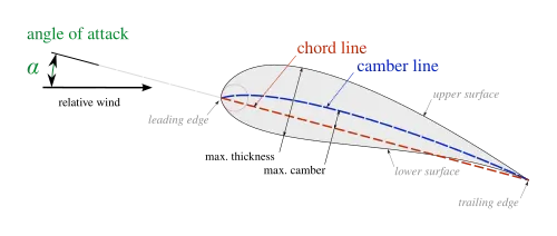
- The suction surface (upper surface) is generally associated with higher velocity and lower static pressure.
- The pressure surface (lower surface) has a comparatively higher static pressure than the suction surface. The pressure gradient between these two surfaces contributes to the lift force generated for a given airfoil.
The geometry of the airfoil is described with a variety of terms :
- The leading edge is the point at the front of the airfoil that has maximum curvature (minimum radius).
- The trailing edge is defined similarly as the point of maximum curvature at the rear of the airfoil.
- The chord line is the straight line connecting leading and trailing edges. The chord length, or simply chord, is the length of the chord line. This is the reference dimension of the airfoil section.
- The mean camber line or mean line is the locus of points midway between the upper and lower surfaces. Its shape depends on the thickness distribution along the chord;
- The thickness of an airfoil varies along the chord. It may be measured in either of two ways:
- Thickness measured perpendicular to the camber line. This is sometimes described as the "American convention";
- Thickness measured perpendicular to the chord line. This is sometimes described as the "British convention".
Other important concepts used to describe the airfoil's behavior when moving through a fluid are[1]:
- The aerodynamic center, which is the chord-wise length about which the pitching moment is independent of the lift coefficient and the angle of attack.
- The center of pressure, which is the chord-wise location about which the pitching moment is zero.
Set up
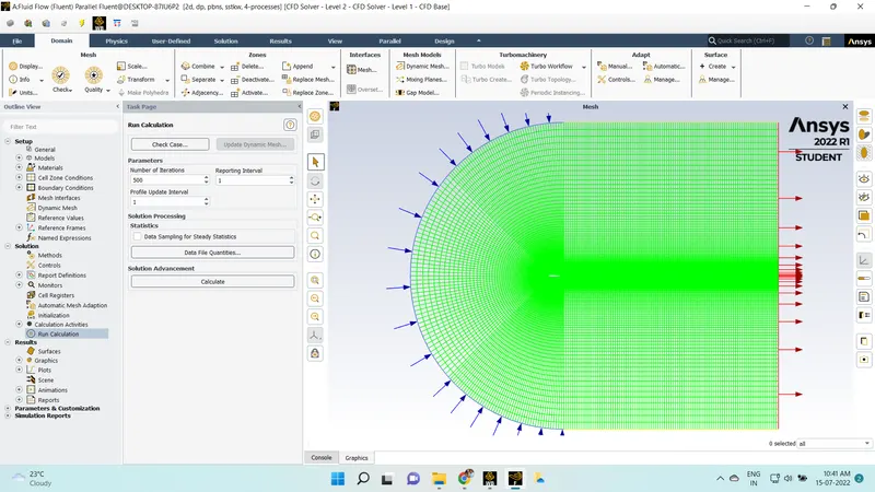
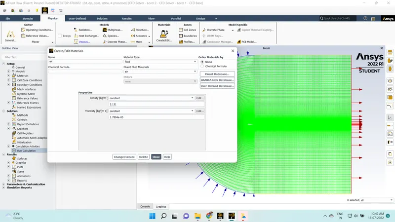
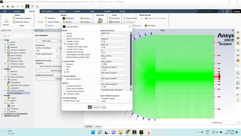
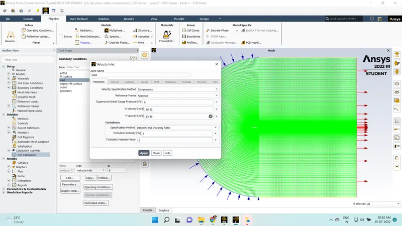
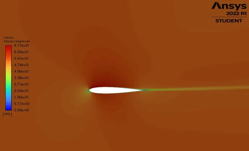
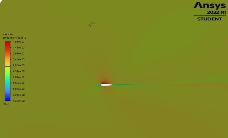
The angle of attack at 5
Cd
-------------------------------- -------------------
airfoil 0.0060994958
Cl
-------------------------------- -------------------
airfoil 0.1975209
The angle of attack at 10
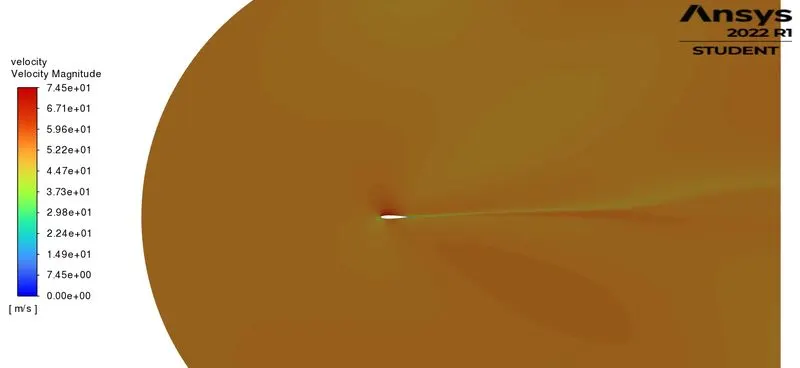
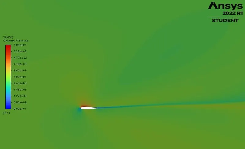
Cd
-------------------------------- -------------------
airfoil -0.0095259525
Cl
-------------------------------- -------------------
airfoil 0.3857867
The angle of attack at 15
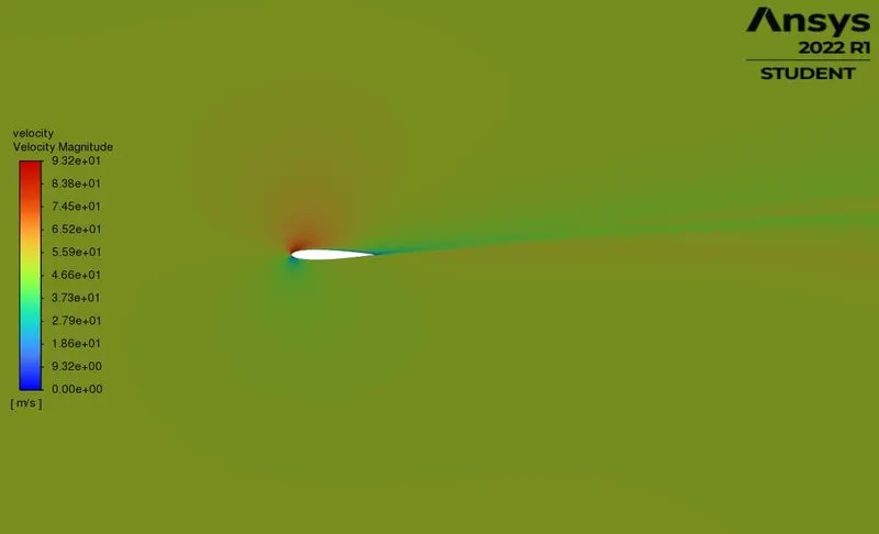
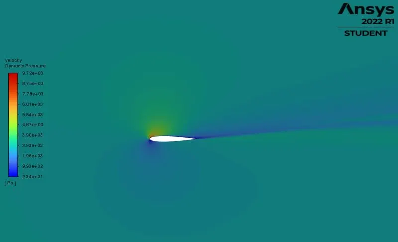
Cd
-------------------------------- -------------------
airfoil -0.085761942
Cl
-------------------------------- -------------------
airfoil 0.77943836
Conclusion
Simulations are done according to the different angle of attacks
and results are compared
found drag and coefficients at different angle of attacks .