Week 7- Meshing of Backdoor Challenge
AIM :
To extract the Midsurface and Mesh the given Car Backdoor component by following the specified quality criteria and assigning thickness using HYPERMESH.
SOFTWARE TOOL USED :
Altair HyperWorks Version 2022
OBJECTIVE :
- Import the Car Backdoor Component, extract the Mid-surface, and Mesh the given geometry with the target element size of 5 units.
- Check all the quality criteria parameters with good mesh quality.
GIVEN DATA :
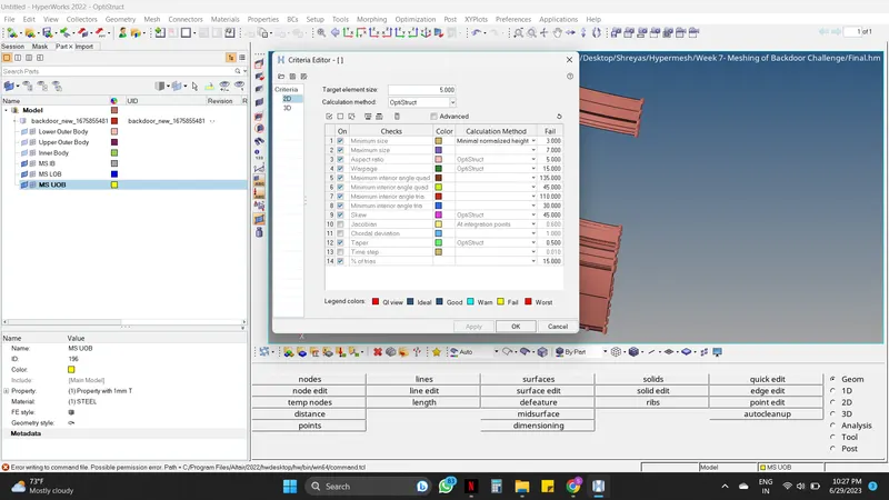
- Quality criteria
| S.N | Quality Criteria | Value |
| 1 | Target Element Length | 5 |
| 2 | Aspect Ratio | 5 |
| 3 | Skewness | 45 |
| 4 | Warping | 15 |
| 5 | Taper | 0.5 |
| 6 | Min. Length | 3 Units |
| 7 | Max. Length | 7 Units |
| 8 | Min angle Quad | 45 |
| 9 | Max angle Quad | 135 |
| 10 | Min angle Tria | 30 |
| 11 | Max angle Tria | 110 |
| 12 | Tria % | 15 |
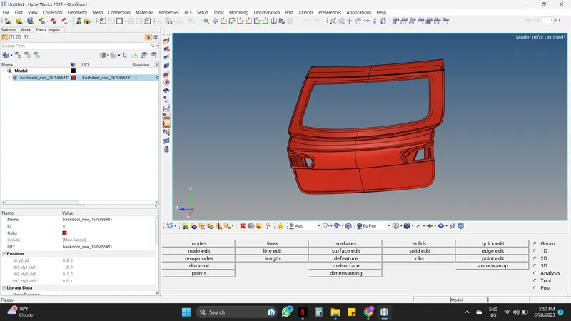
- Cad Model
THEORY :
1. Computer-Aided Engineering (CAE) :
Computer-aided engineering (CAE) is the use of computer software to simulate performance in order to improve product designs or assist in the resolution of engineering problems for a wide range of industries. This includes simulation, validation, and optimization of products, processes, and manufacturing tools.
A typical CAE process comprises of Pre-processing, Solving, and Post-processing steps. In the pre-processing phase, engineers model the geometry (or a system representation) and the physical properties of the design, as well as the environment in the form of applied loads or constraints. Some of the Pre-processors are ANSA and Hypermesh. Next, the model is solved using an appropriate mathematical formulation of the underlying physics. Some of the solvers are ABAQUS (for durability analysis), NVH (for noise, vibration, and harshness analysis), and LS DYNA (for crash, safety, and impact analysis). In the post-processing phase, the results are presented to the engineer for review. Some of the Post-processing are METAPOST and HYPERVIEW.
2. HYPERMESH :
Altair HyperMesh is a high-performance finite element pre-processor that allows users to prepare even the largest models, and produce fine-tuned, high-quality surface meshes of their CAD geometry starting from the import of CAD geometry to exporting an analysis run for various disciplines.
With HyperMesh, you get advanced control over the type and style of meshing done on each CAD face or edge along with many automated tools to make complex meshing tasks a piece of cake. With the high-quality surface meshes from HyperMesh, you can create powerful and efficient 3D meshes for use in Computational Fluid Dynamics (CFD), Finite Element Analysis (FEA), Smoothed particle hydrodynamics (SPH), and more.
3. Car Back Door :
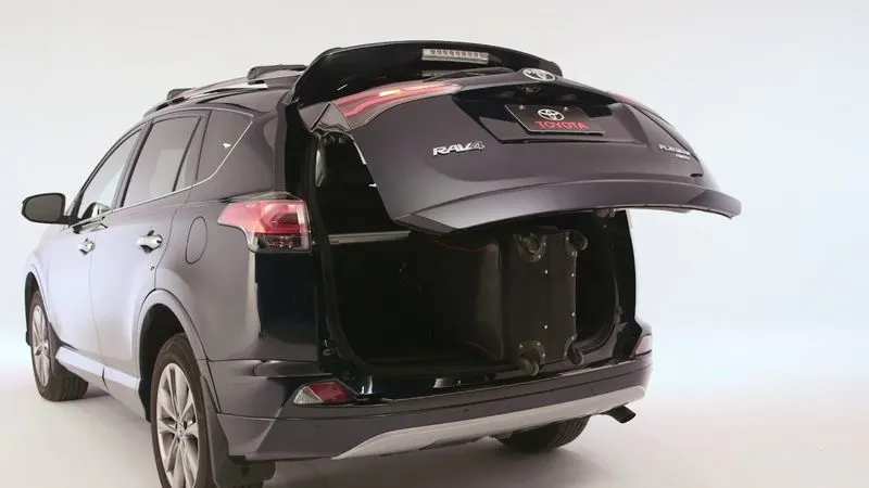
The back door is a hinged door/tailgate at the rear of the vehicle. It may be used for loading and unloading cargo, or to get passengers in and out, in case there are seats present at the rear. The back door comprises certain components which form the back door assembly together.
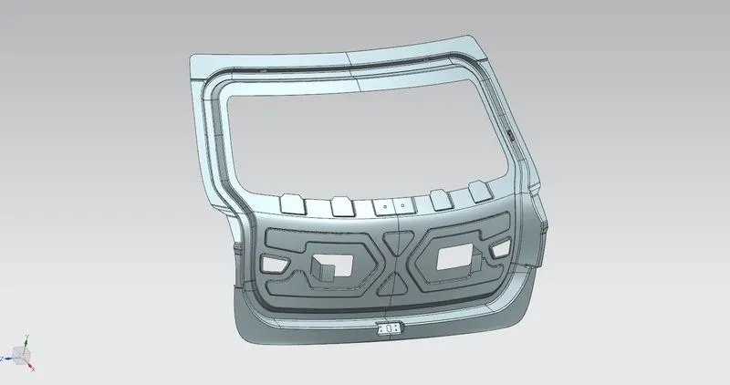
- Inner Panel
The inner panel, as the name suggests, is the inner part of the door. It is where most of the reinforcements and components are mounted. It is manufactured either by casting (aluminum) or sheet metal stamping (steel).
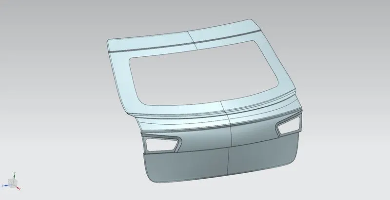
- Outer Panel
As the name suggests, it is the outer part of the rear door and is mostly responsible for the aesthetics of the vehicle. Outer and inner panels are connected by mastic sealants in the center and by a hemming process at the edges. The outer door handle and in some cases, the number plate may also be installed on the outer panel of the back door. We have considered a 2-part outer panel for our design, outer upper panel and outer lower panel prospectively. The outer panel is manufactured by stamping sheet metal.
4. Geometry Clean-up :
Designers have different priorities while creating CAD geometry than analysts who are seeking to use the data. Usually, a single smooth surface is divided into smaller patches, each of which is a distinct mathematical face. And often, there will be gaps, overlaps, or other alignment issues at the junction of two surfaces.
In geometry cleanup, analysts integrate several faces onto a single smooth surface to make the geometry more suitable for meshing. This enables the creation of the elements across the entire region at once and eliminates the need for false or unintentional edges in the finished mesh.
Some commands for the geometry cleanup are as follows :
- Geometry -----> Edge edit -----> Replace
- Geometry -----> Surfaces -----> Ruled
- Geometry -----> Quick edit -----> Filler surface
5. Meshing/Mesh generation :
Mesh generation is the process of discretizing the entire model into smaller elements in other words Mesh is a network that is formed of cells and points. Meshing is often used in FEA and CFD domains.
There are two types of meshing, 2D Mesh & 3D Mesh. In 2D Mesh, the mid surface is extracted from the component and then meshing is done on the mid surface whereas in 3D Mesh, direct meshing is done on the component from inside out. The difference between the 2D & 3D mesh is that the mesh type in 2D Mesh is mixed whereas in 3D Mesh the mesh type is Ortho tria (for complex regions such as fillets and hemmings) or Tria (For regions that are flat and not as complicated).
PROCEDURE :
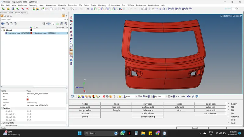
Step 01 : Importing CAD Model.
- The initial step is to import the geometry into HYPERMESH Software.
Import Model -----> Import Geometry -----> File type - IGES ----> Select Location -----> Click Import -----> Fress F to fit the model.
Step 02 : Geometry Cleanup.
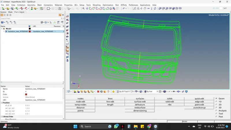
Check if there are any extra surfaces, free edges, or missing surfaces are present or not. For this enable wireframe geometry mode and then try to observe and find irregularities and discontinuities in the model. If found then fix it manually.
Step 03 : Separating & Organizing of the Components.
- Working on the whole component will make the process more complicated and time-consuming.
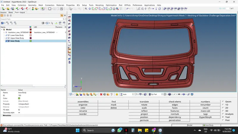
- For making the process easy and consume less time the separation of the whole component must be done as per the engineer.
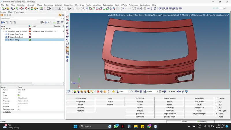
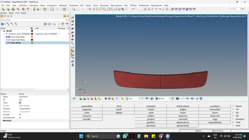
- Here the whole car backdoor component is separated into 3 different components named Inner body, Lower outer body, and Upper outer body.
- For separation use the mask command and for assigning them into different components use organize command.
Mask Command :
Tool -----> Mask -----> Select the surfaces which need to be separated -----> Mask -----> Reverse.
Organize Command :
After reverse, Tool -----> Organize -----> Collectors -----> Surfs -----> Select the whole surface -----> Create a component by mouse right clicking on tab area, Create component ------> Select the created component in Deck Component -----> Move.
Step 04 : Identify and delete the symmetry surfaces.
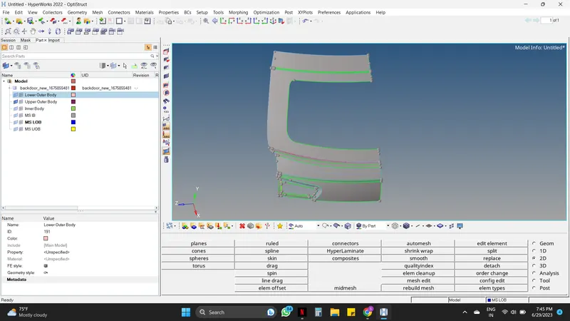
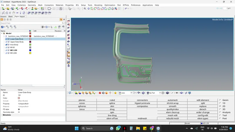
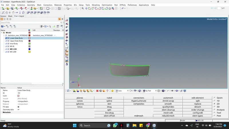
- Here the component is similar on both sides, Hence deleting one side of the symmetry surfaces and performing all the operations on one side, and reflecting on the other side will make the process more easy and time-saving.
- For deleting the half component surface follow the below steps,
Toolbar -----> Red Cross Symbol (Delete symbol) -----> Select one side of the symmetry surface -----> Delete entity.
Step 05 : Geometry Autocleanup and Midsurfacing
- Car's Back doors have some very complicated features, hence the geometry cleanup is very necessary.
- Hence Before and After extracting the mid surface the Geometry Autocleanup must be done.
Geometry -----> autocleanup -----> Edit the parameters and criteria as per the requirements -----> Select the surface -----> autocleanup.
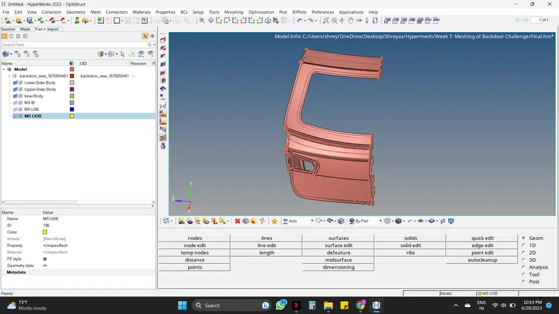
- The mid surface is generated to reduce the complexity as by simplifying the cad model we get more accurate simulation results in a shorter time.
- In Hypermesh there are many ways to extract the mid surface, an engineer must try to take the exact mid surface on every edge, curve, and complex area. Capturing the exact mid-surface is important because it can later lead to irregular mesh flow and quality issues during meshing.
The following approaches are some methods to extract mid-surface.
- Offset Approach.
- Offset + planes + sweep Approach.
- Offset + planes Approach.
- Skin Offset Approach.
Offset Approach :
Geometry -----> Midsurface -----> Automidsurface ----> Select the Extraction options and in that Offset -----> Now select auto extraction again -----> Select the component -----> Extract.
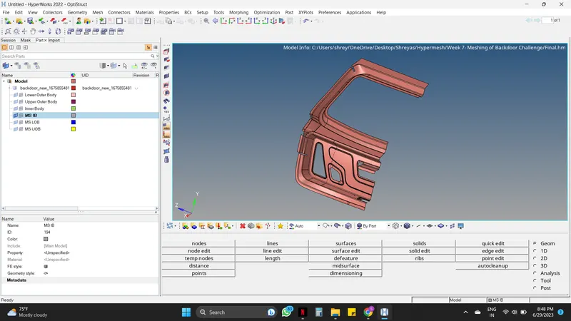
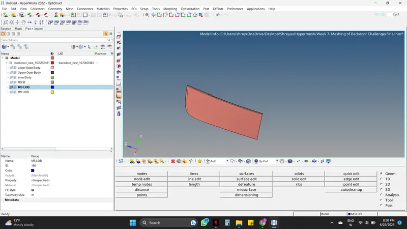
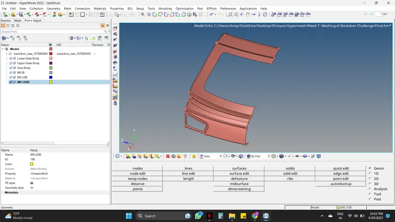
Step 06 : Assigning of Material, Property & Thickness.
- Here new property and material must be created for assigning them to the Backdoor component.
For creating Material :
Mouse right-click on the Tab area -----> Create -----> Material.
For creating properties :
Mouse right-click on the Tab area -----> Create -----> Property.
- While creating the property give the thickness (T) as 1.
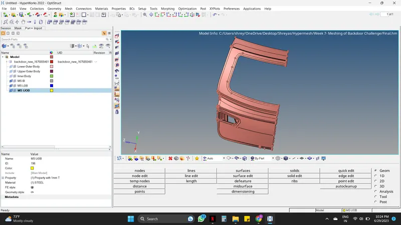
Step 07 : Setting up the Quality Criteria and Mesh Parameter.
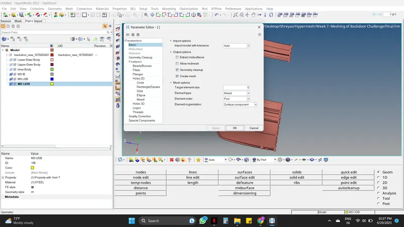
- Setting up the quality criteria as well as the mesh parameters is very important in every pre-processing process. This will make the mesh proper as per the requirements. Here the parameters are given, as per the given data fill the dialogue box, and apply to the component.
For Mesh Parameter :
Title bar -----> Preferences -----> Parameter file setting -----> Basic -----> Fill the necessary data as per the requirement (Target element size : 5, Element type : Mixed) -----> OK.
For Quality Criteria :
Title bar -----> Preferences -----> Criteria file setting -----> Change the criteria values as per given data -----> Fill the necessary data as per the requirement (Target element size : 5, Element type : Mixed) -----> OK.
Step 08 : Mesh Generation
- As the Back door component is separated into three different components, the mesh must also be done one by one for all three components.
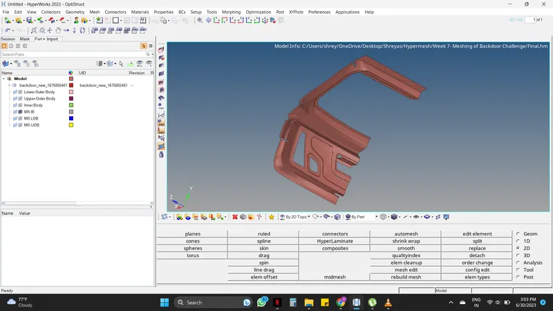
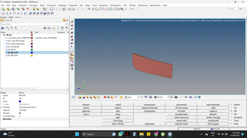
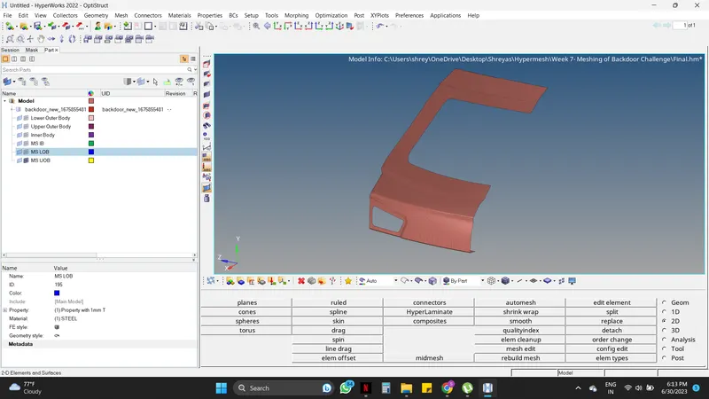
2D -----> Automesh -----> Enter element size as 5mm ----> Mouse Right-click on the Surfs and Select displayed -----> Mesh.
-
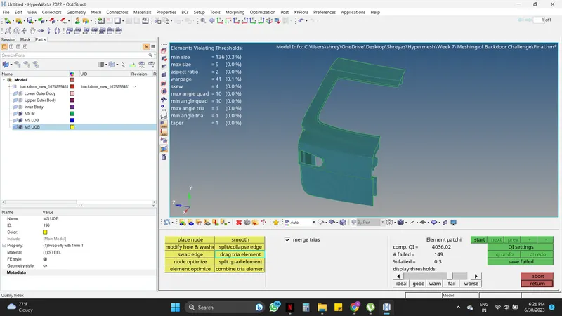
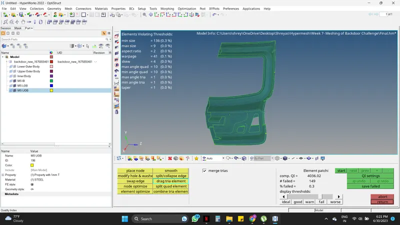
After Meshing there will be some errors that will not follow the quality criteria and will be seen in different colors. To make the mesh proper some manual adjustments must be done, for that there are a few commands i.e. Create element, Split element, Combine element, smooth, drag tria element, delete element, etc.
- Create element : 2D -----> edit element -----> Create -----> Select nodes where the element must be created -----> Create.
- Split element : 2D -----> edit element -----> Split -----> draw a splitting line by points -----> Split.
- Combine element : 2D -----> edit element -----> Combine -----> draw a splitting line by points -----> Split.
- Smooth : 2D -----> qualityindex -----> Smooth -----> Select the elements which need to be smooth -----> Mouse middle click.
- Drag tria element : 2D -----> qualityindex -----> drag tria element -----> Select the elements which need to be smooth -----> Mouse middle click.
- Delete element : Toolbar -----> Red Cross Symbol (Delete symbol) -----> Select the element that must be deleted -----> Delete entity.
- Rebuild Mesh : 2D -----> Rebuild mesh -----> Select the element which needs to be remeshed -----> Rebuild.
- After using all the above commands the mesh can be created properly and with minimal errors.
Step 09 : Creating the other symmetry half and joining it.
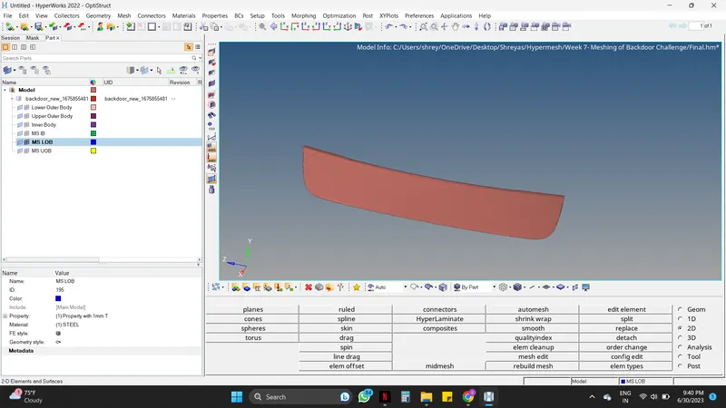
- As shown in the above fig the Mesh is done with the help of different commands (explained above). Since the meshing is done of the half Car Backdoor Midsurface now the other half surface must be mirrored/reflected.
This is done by following the steps,
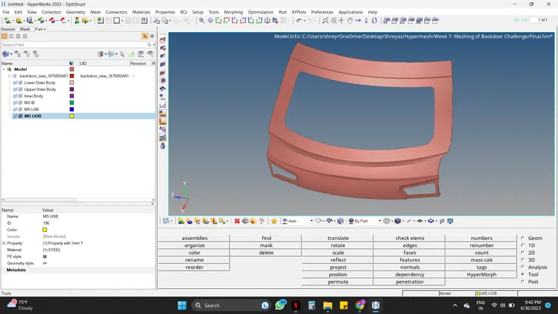
Tools -----> Reflect -----> Select the elements which need to be reflected (as shown in fig below) -----> Select Duplicate and the reflect must be with respect to the y-axis & select the base -----> Reflect.
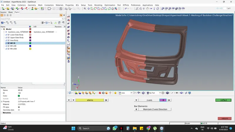
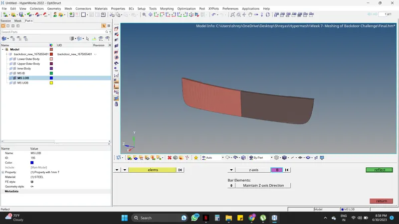
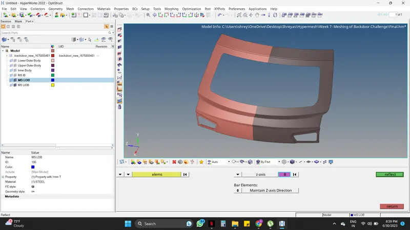
- Here the other halves are created but they are not joined with the first halves. Hence they must be joined and for doing that following steps must be followed.
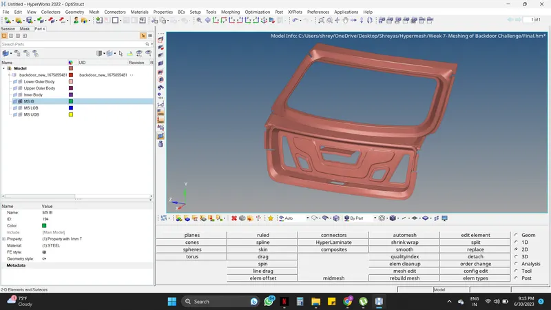
Tools -----> Edges -----> Elements -----> Select the whole component -----> Preview equivalence -----> Tolerance : 0.1 -----> Equivalence.
Step 10 : Checking the Normals.
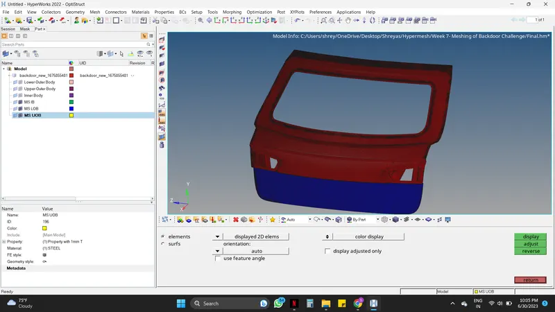
- Checking Normals.
Tools -----> Normal -----> Display -----> Adjust.
- Hence the component (Car Hood) is ready for further operations.
LEARNING OUTCOMES :
By doing this challenge, the following aspects can be learned:
- Basic tools in Hypermesh
- Extracting mid-surface in Hypermesh
- Generating a 2D mesh on the extracted mid-surface.
- Using reflect command to reflect.
- Assigning the thickness to the mid-surface.
- performing basic checks at the end.
CONCLUSION :
- Extracted the mid-surface of the given Car Backdoor model.
- Generated a 2D mesh on the component based on the given quality criteria & parameters, deleting the half component and reflecting it for making the process easy and time efficient, and assigned the thickness.