Week 7- Meshing of Backdoor Challenge
2D meshing of backdoor Component
Aim: To understand the model and extract mid surfacing and mesh the model.
Objective: To mesh the given backdoor geometry of a car through manual midsurfacing process. To also ensure that mesh is of highest quality with low number of trias and good mesh flow.
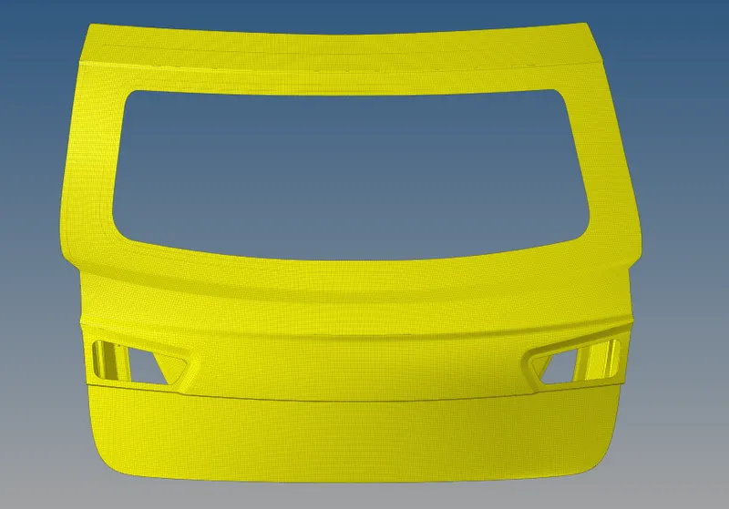
CAD model image:
It is comprised mainly of the following components: Inner, outer amd lower.
PROCEDURE
1. The part needs to be meshed component by component so we need to pick one of them and extract its midsurface. We will need to carry out this manually. Firstly, a new component is created and we'll name it 'MS of X': X being the component that we will be working on.
2. After that, we can go to the component to be midsurfaced and measure its thickness. Which is 0.75 mm in this case. We need this for manual creation of midsurface. And this is done using the offset tool under surface edit.
3. The offset tool requires a measurement half of the thickness. Which would be 0.375 mm in this case. We can select any one face from any one of the faces. And then, right click surfaces and select 'by face'. When this is done, the entire face is selected. Not the entire component.
4. Before carrying out this step, we need to ensure that the newly created midsurface component is our current component. After confirming, we can select 'duplicate' by selecting surfaces again. And now, we can select 'current component'. The offset of the component is now transferred to our newly created component. But we are yet to offset the face.
5. i. As is customary with meshing, we should start meshing from a certain region and work our way from that region (preferably one with more free edges). To help with this, we can make use of cut lines (quick edit > split surface node) to split the surface into smaller surfaces for better mesh control.
ii. Additionally, we need to toggle lines that would hinder mesh flow and use our best judgement to make sure that the surfaces we create do not encourage tria formation (like pointed edges).
iii. After mesh is created, we can clean the mesh using various tools. Primarily, we will be using the element optimize tool, the drag tria tool and to an extent, the swap edge tool. These are accessed from the quality index section in the 2D menu.
iv. After we take care of each surface (meshing and cleaning up), we can move onto the next. The process is repeated until we mesh the entire component.
6. Since the component is halved, we will need to make use of the reflect tool to create the other symmetrical half. Reflect tool can be accessed by going to the tools menu. We will need to select the elements to reflect first. Do take care not to select regions that are not otherwise part of the other half, since both halves may not be completely symmetrical. And then we can select the axis on which we are reflecting and then the base point. After that, we need to right click 'elements' in the reflect toolbar and select duplicate. And then we can click reflect. This will create the mirrored half of the current component.
9. We will now check for equivalency by going to the edges section in the tools menu and previewing equivalance for varying tolerances (ranging between 0.2 mm to 2 mm). This is to ensure there are no misaligned elements or free edges, which we can also check using a different option in the same section. The preview equivalence option shows us the nodes that require equivalencing. They are rectified by clicking the 'equivalence' option in the menu. If some nodes haven't been tended to, it may require manual fixing, using the replace node option (F3).
10. After equivalencing, we can check for duplicates through the check elements tool in the same menu. If duplicates exist, we can click 'save failed', move on to the tool menu, select the 'delete' tool, select elements, right click element and select retrieve and then click the delete button. This should handle the duplicates.
FINAL MODEL IMAGES (MESHED)
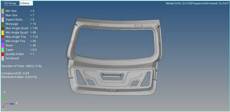
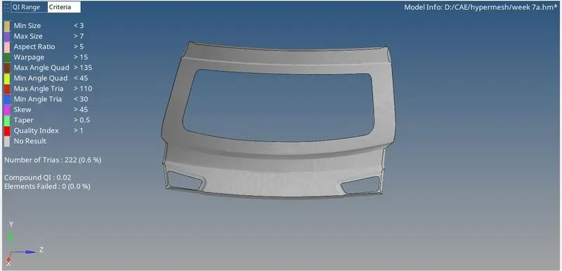
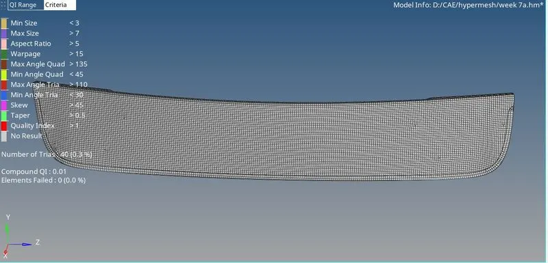
- Tria Management
- Avoig higher number of trias.
- Important Parameter's in tria management
- No trias in corner's or edge's.
- No opposite trias.
- No back to back trias.
- No trias in fillets or hemmings(We can have minimum but anyhow try to avoid).
- No rotational quads.
- No trias should share a boundary with feature line.
- Connectivity between elements.
- Split and perform the mesh.
- Use mixed type mesh for irregular shaped surfaces and quads only for rectangular/square surfaces(Opposite sides should be parallel and equal).