Week 7-Long Piston With Cam
AIM
- To perform a transient analysis on the piston and cam mechanism model.
OBJECTIVE
- To run the analysis on the piston and cam mechanism with frictionless contact, frictional contact with 0.1 and 0.2 for a total number of 3 cases. This needs to be followed with transient analysis for the piston and cam mechanism model.
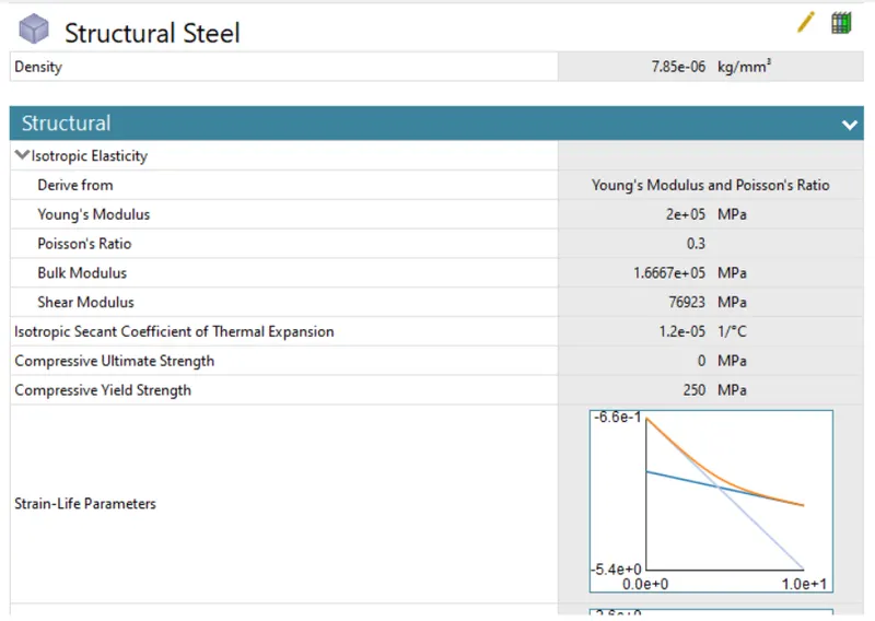
MATERIAL PROPERTY
Structural Steel
PROCEDURE
- Importing the geometry in the space claim module of the long piston with cam to the geometry and its surface, also to check whether the geometry damages.
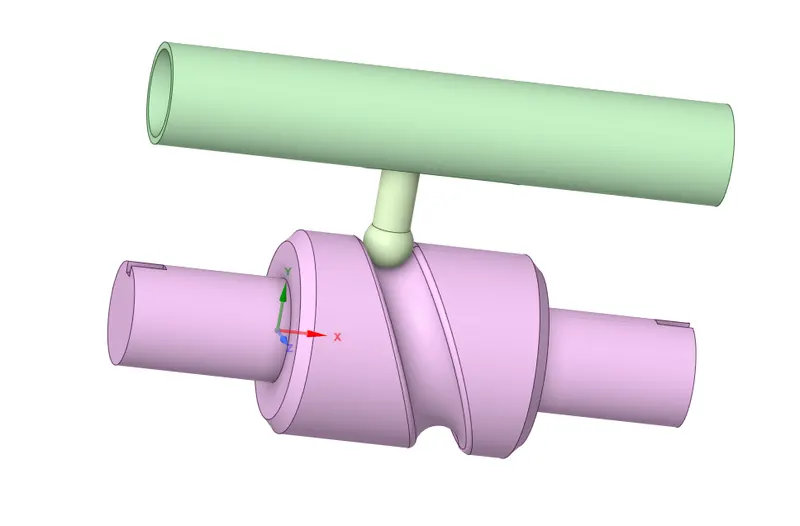
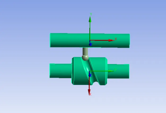
- And then opening the model in the mechanical module, renaming each part such as barrel, bareel_CAM, and CAM_follower. The barrel and breel_CAM will be the rigid body in stiffness behavior.
Connections
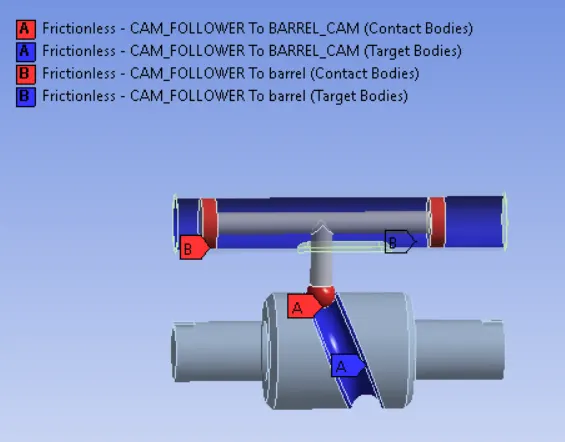
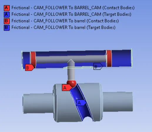
- The contacts are changed by (flip/contact target) and then for case 1 giving the contact type as frictionless, for others Cases Frictional value 0.1 to 0.2. The faces of the body of the contact are selected only 2 faces of cam_follower.
Case 1 Case 2
Joints
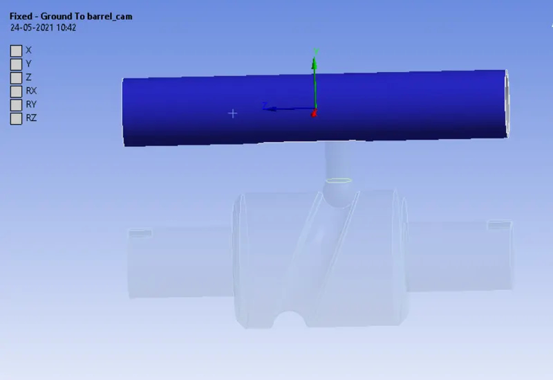
- The barrel of the body would be fixed so the fixed body to the ground joint is given by selecting the face of the barrel.
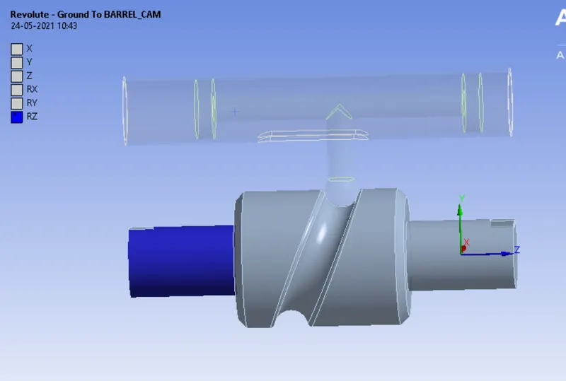
- The barrel cam will be rotating and following the follower path, so for rotation motion, the revolute barrel to cam joint is provided with selecting 1 face of the barrel_cam.
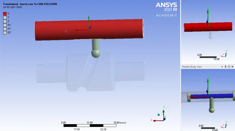
- The follower is attached to the barrel is translates the motion to the follower so the transitional join is given with selecting the body to body by selecting the inner barrel with the outer barrel rotating in the same x-axis.
Mesh
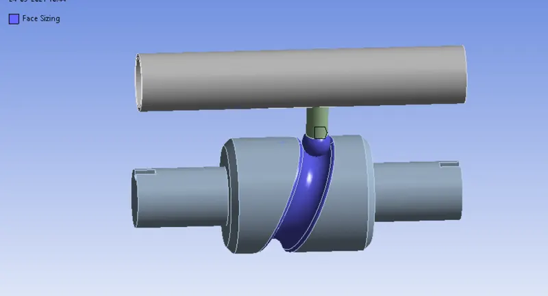
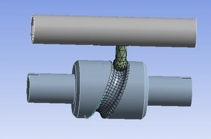
- The face sizing is given for the barrel_cam and follower by selecting with 7 faces of the geometry and then elements size is 3mm.
Analysis settings
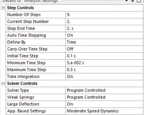
- The setup for this simulation is given for 9 steps for step 1 the settings are different with the auto time step ON, with initial time step 0.1s, minimum time step (5e-2s), and a maximum time step of (0.2s). The large deflection is ON, with stabilization is Constant, Energy dissipation ratio 0.1, and Activation for the first substep is ON (YES) and output control are on except contact / general miscellaneous is OFF (NO).
- For steps 2 to 9 the initial time step 0.1s, the minimum time step (5e-2s), and the maximum time step of (0.3s).
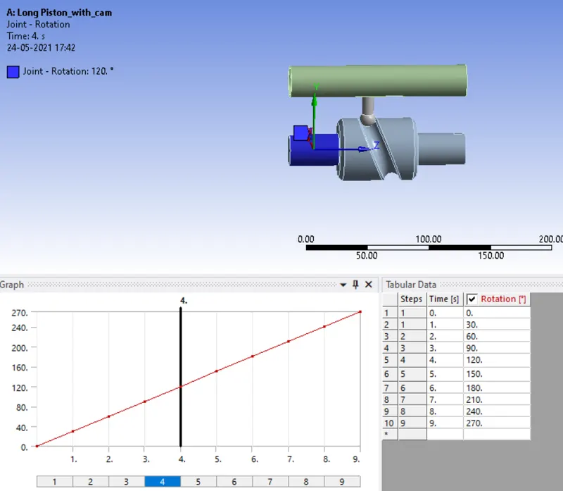
- A joint rotation is given for the barrel to revolve at a particular angle for each following with 30 degrees to 270 degrees.
RESULTS
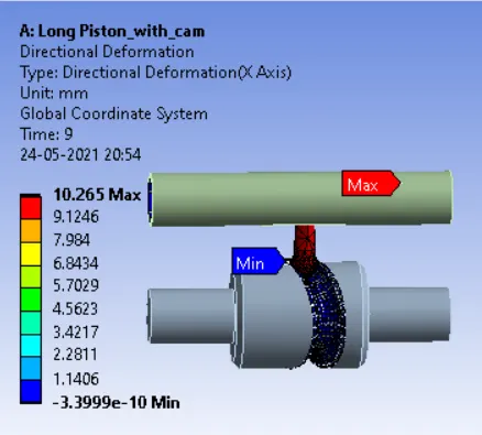
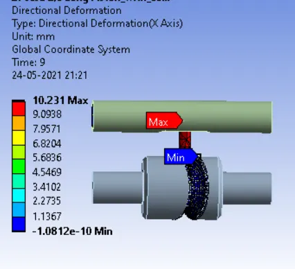
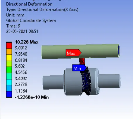
Directional Deformation
Case1 – Frictionless Case 2 – Friction-0.1 Case 3 – Friction-0.2
Equivalent stress
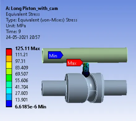
Case1 – Frictionless Case 2 – Friction-0.1 Case 3 – Friction-0.2
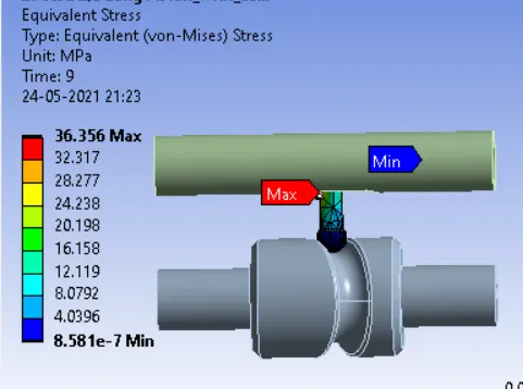
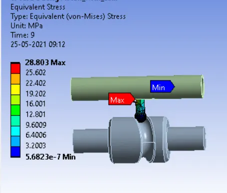
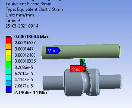
Equivalent strain
Case1 – Frictionless Case 2 – Friction-0.1 Case 3 – Friction-0.2
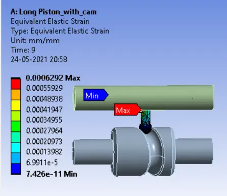
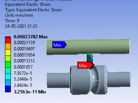
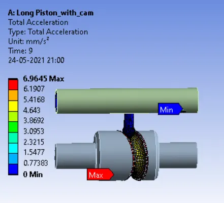
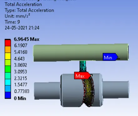
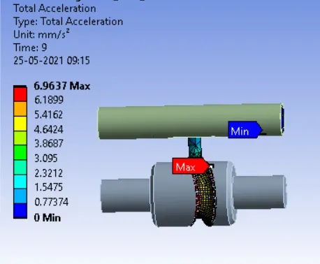
Total Acceleration
Case1 – Frictionless Case 2 – Friction-0.1 Case 3 – Friction-0.2
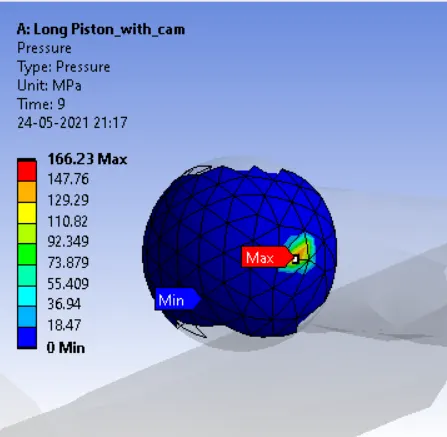
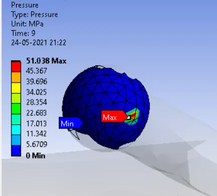
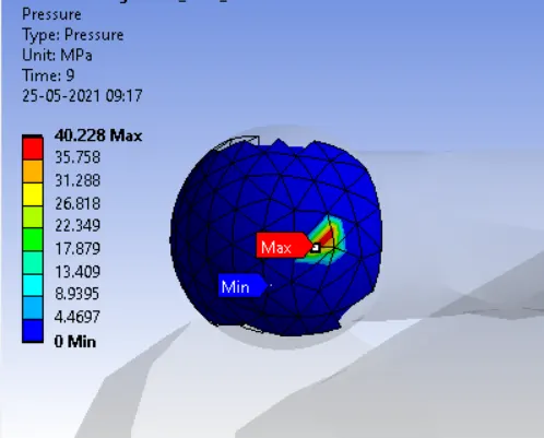
Contact Pressure
Case1 – Frictionless Case 2 – Friction-0.2 Case 3 – Friction-0.2
CONCLUSION
| Directional Deformation (mm) | Equivalent strain | Equivalent stress (MPa) | Contact Pressure (MPa) | |
| Case 1 | 10.265 | 0.000629 | 125.11 | 166.23 |
| Case 2 | 10.231 | 0.000237 | 36.356 | 51.038 |
| Case 3 | 10.228 | 0.000186 | 28.803 | 40.228 |
- As we know that it is never possible to have complete frictionless contact between cam and follower.
- So, minimum friction is desired for any mechanisms.
- As per results, we can observe that as the friction increases, stress and strain values increase, and deformation due to higher pressure also increases.
- When friction is higher, pressure on the tip of the follower, where it is in contact with the cam, gets deformation. It can bend or twist due to the following path of the cam.
- So, minimum friction between cam & follower gives better results as in CASE_3.
- Friction coefficient plays the important role in cam & follower because of the transmission of the rotary motion to translation motion. Also, the following path is also important.
- In barrel type of cam, there can be the number of turns that are followed by the follower, so by minimizing the friction, we can achieve better results in terms of proper transmission and it the mechanism can work longer.