Week 7-Long Piston With Cam
PISTON WITH CAM FOLLOWER SIMULATION
OBJECTIVE:
To perform a transient analysis on a piston and cam mechanism where a follower is in contact over a cam that rotates about an axis perpendicular to the axis of the cam. The analysis is performed with three different cases - frictionless and frictional coeff as 0.1 and 0.2. The Equivalent Stress, Directional Deformation and Equivalent Elastic Strain are extracted and compared in all three cases
PROCEDURE:
- Create a new transient structural simulation
- Import structural steel as the desired material for all the components
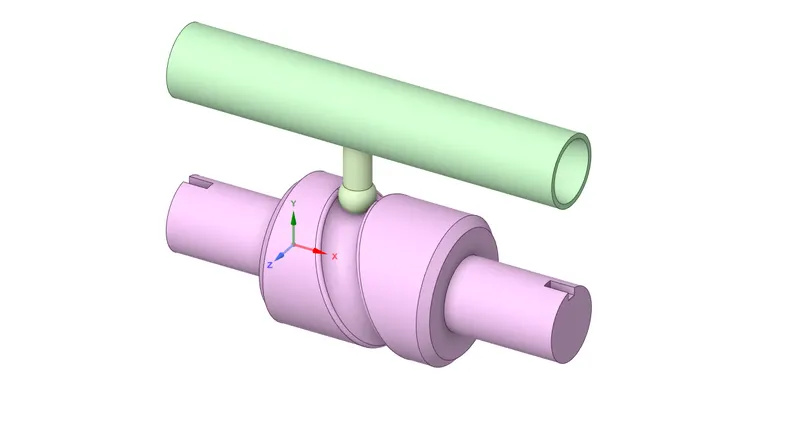
- Import the geometry file onto the Spaceclaim GUI.
- Then the model module of static structural is again updated.
- Open the model in ansys mechanical module.
Material assignment
The structural steel is added to all the three components
Contact region
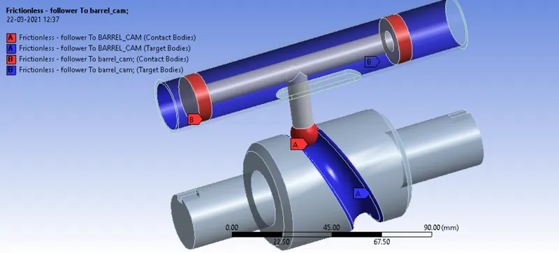
Contact between the piston follower and the barrel that contains it is set as frictionless
Contact between the cam and follower is also considered frictionless
NOTE: Both the contacts are frictionless in case 1 and differs as Mu = 0.1, 0.2 in case 2 and 3 respectively
Joints
Set the joint of the barrel with reference to the ground as fixed.
Create a revolute joint for the cam rotation and specify the cylindrical faces of it for scope. Make sure this rotates about the z axis.
Create another body-to-body translational joint for the piston follower and the barrel (fixed)
Mesh
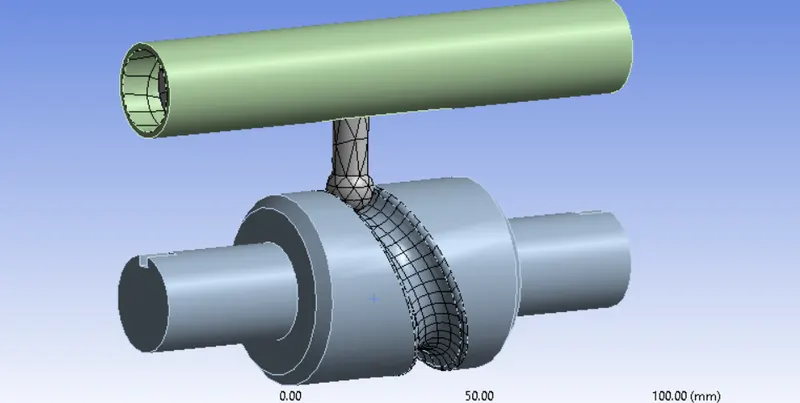
The cam and the barrel are defined as rigid and hence the deformation will not be computed at these regions. Hence they will not be meshed either
A sizing of 4mm is set for contact regions and set adaptive mesh sizing to off
Analysis settings
A total of 9 time steps are created which defines that the load will be gradually applied and retracted after the 5th time step.
Large deflection = on
Direct solver
Joint load
THe revolute joint is applied a joint load with angular displacement about 30deg increment at each time step

RESULTS
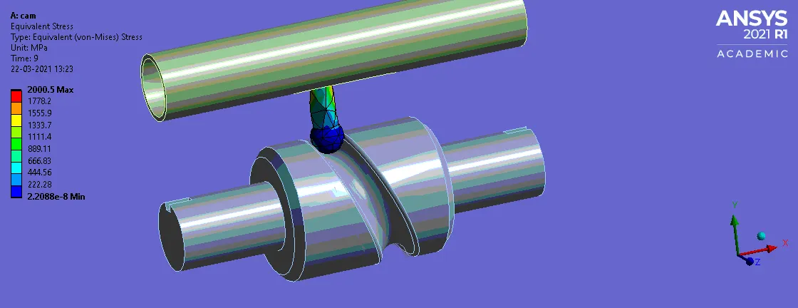
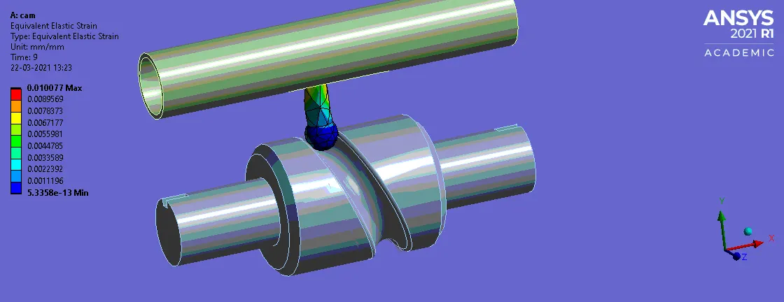
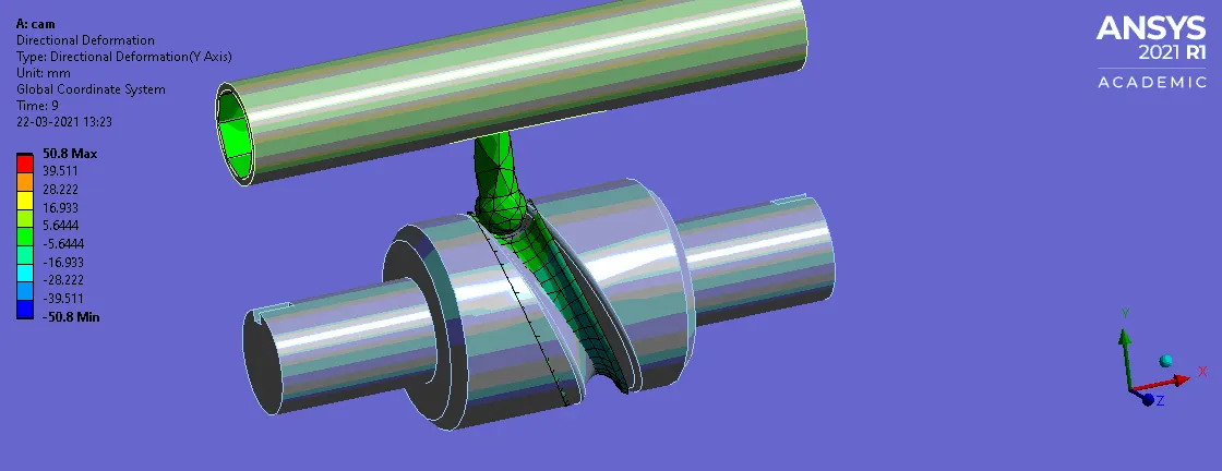
CASE 1: Frictionless contact
Equivalent stress
Equivalent strain
Directional deformation
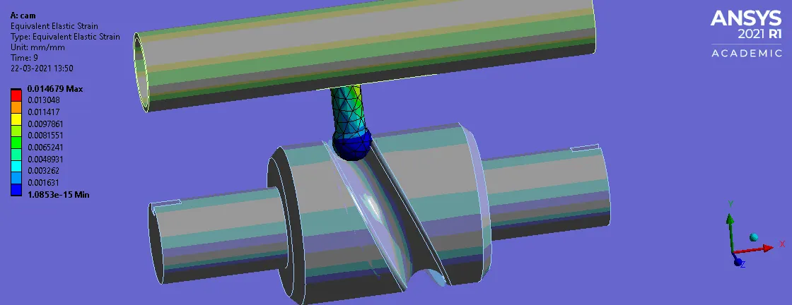
CASE 2: Mu = 0.1
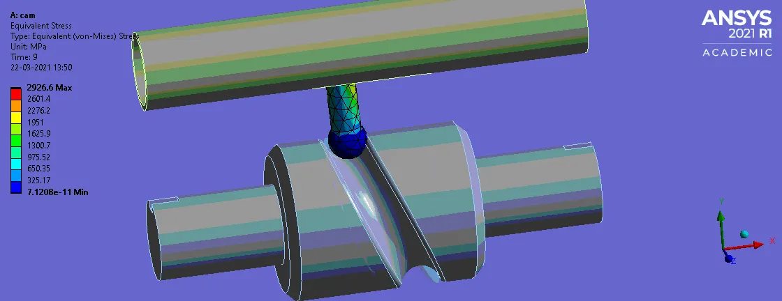
Equivalent stress
Equivalent strain
Directional deformation
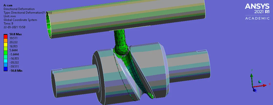
CASE 3: Mu = 0.2
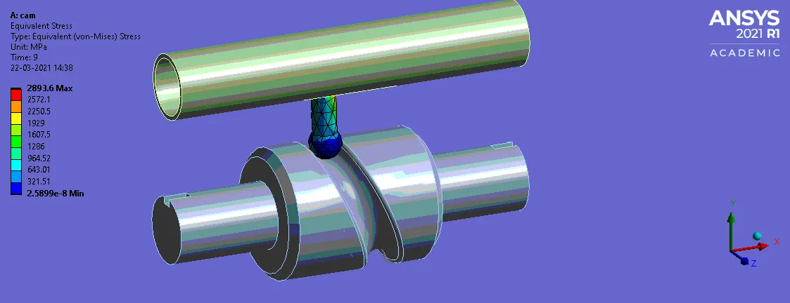
Equivalent stress
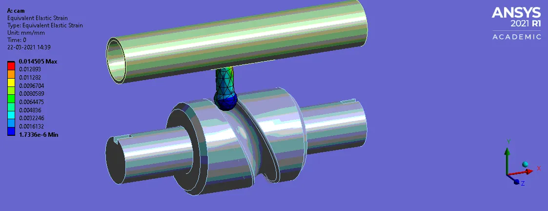
Equivalent strain
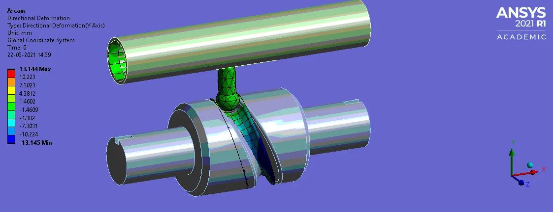
Directional deformation
CONCLUSION
From the above results we can conclude that, it is obvious that once the contact between the components are frictional, the stress level generated at these regions increase. From the above results we can notice that the max stress generated increase to 2926 MP and 2893 MP from 2000MP due to introduction of a frictional contact with a coeff of friction value as 0.1 and 0.2 respectively. While the stress generated is case3 is less than that of case 1, this may be due to a coarse mesh. However if refined further it could be less significantly higher.