Performed the Automotive Pedestrian Protection Test using Pedestrian Head-form Child V1.0 with EC 78/2009 Regulation.
Title -
Performed the Automotive Pedestrian Protection Test using Pedestrian Head-form Child V1.0 with EC 78/2009 Regulation.
Aim -
To perform the Automobile Pedestrian Impact using Pedestrian Headform Child V1.0
Objective -
- Work with a real-life industry-relevant complicated model.
- Calculate acceleration and HIC for 40 kmph velocity impact at an angle between 35-75 degrees.
- Use of Bonnet for impacting the pedestrian.
Introduction -
Head injuries in pedestrian/automobile impacts are among the most common and most harmful of all pedestrian impact inquiries. Field studies, experimental studies, and analytical simulations all show that when pedestrians are struck by the front of an automobile, they are generally thrust onto the hood or fender, and sometimes onto the windshield. Pedestrian impacts onto the hood, fender, or windshield generally result in a head impact injury.
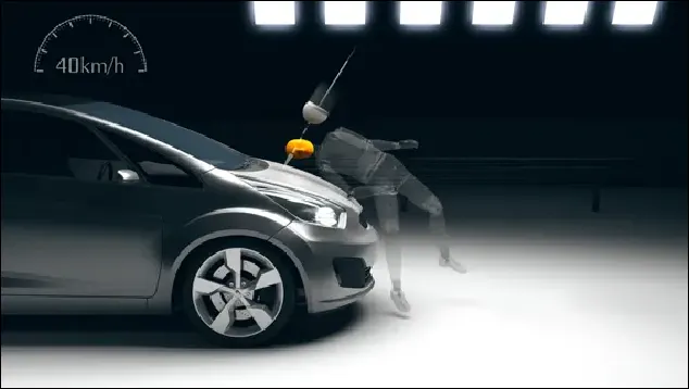
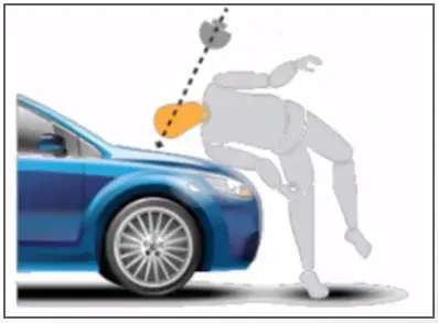
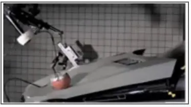
Upon impact, the softness of the hood or fender greatly affects the severity of the head injury. If the impact is to a relatively flat region of the hood, sufficiently high above the motor and frame understructure, the deformation of the hood will absorb the energy of the impact and thus reduce the injury severity. Alternatively, if the impact is to a "hard" spot, the injury severity will increase. Especially hard regions are the seams between the hood and the fender and between the hood and the windshield or cowl.
In this article, we develop and present procedures for evaluating hood/fender/cowl impact response and design. Specific designs are presented for softening the fender seam while maintaining the overall integrity of the fender. The designs are evaluated by calculating head injury criteria (HIC) values.
HIC [Head Injury Criterion]
Head Injury Criterion / Coefficient is a quantification of head injury
A widely used measure of the head injury occurring from direct head impact is the HIC. Although there are recognized problems with the HIC. It has nevertheless been shown to roughly correlate with the severity of the injury for pedestrian accidents. The HIC is calculated from acceleration time data according to the formula:
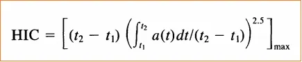
where a is the acceleration of the head mass center expressed in g (gravity acceleration), t is time and t) and t2 (t2 > t) are two points in the impact time interval chosen to maximize the resulting HIC value. A HIC value of 1000 has been identified as a threshold value for a severe head injury.
To find the HIC value the user performs the 3 cases to find out the result for each case.
Case I - Simple Head Impact with the Rigid Wall
Case II - Impact of the Pedestrian Headform with the Rigid Wall
Case III - Impact of the Pedestrian Headform with the Meshed Hood
Stepwise Explanation of Test:
Case I -
Case I is the study of the impact of the simple head model on the planar rigid wall. The value of HIC is calculated based on the impact made by the simple head with the rigid wall and compared with the other two cases on different aspects like material, geometry, boundary conditions, and the initial velocity applied.
#SETTING UPO THE MODEL
1. Opened the Simple Head keyword file in the LSPP
The user opens the readily available simple head keyword file in the LSPP using the file command.
File ----> Open ----> LS DYNA Keyword File (Ctrl + K)
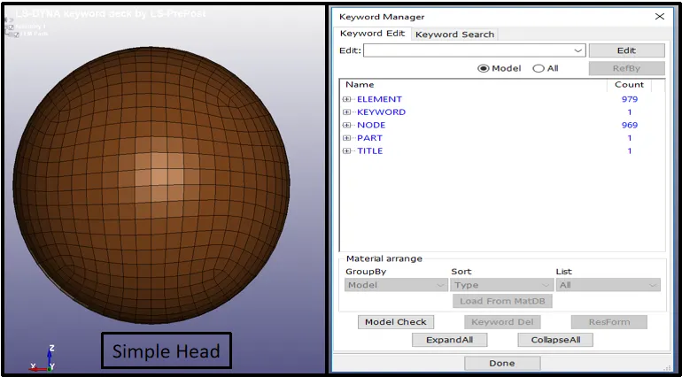
figure 1. Import the Simple Head Keyword in LSPP
2. Creation of the Rigid Wall
Once after importing the simple head, a rigid Wall is created using the create entity option and the planar rigid wall is created perpendicular to the base of the simple head.
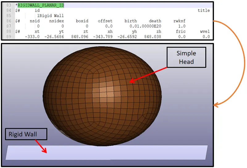
figure 2. Rigid Wall Creation in LSPP
3. Creation of Section Card
Section Card is used for defining the element formulation, integration rule, nodal thicknesses, and cross-sectional properties. All section identifiers (SECIDs) defined in this section are unique. Here the user used the ELFORM 2 to define the element formulation and the rest of the parameters are kept as default.

figure 3. Section Card Definition in LSPP
4. Creation of Material Card
The user defines the material card to define the material for the head. The properties of the material are taken similar to rigid body properties. To define the material for the head the user uses the #MAT keyword and assigns the below values.
Density = 12.90e-06 Kg/mm^3
Young's Modulus = 207 GPA
Poison's Ratio = 0.28
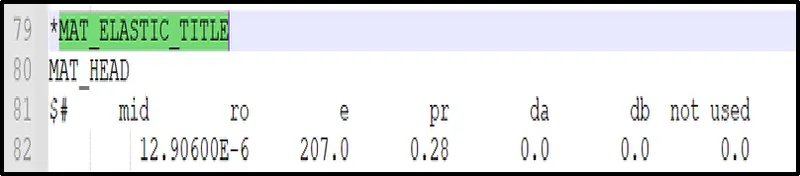
figure 4. Material Card Definition in LSPP
5. Assignation of Material and Section Card
After defining the section card and the material card the user assigns this keyword card to the part which is Simple Head in this case.

figure 5. Assigning Section & Material to Part in LSPP
6. Creation of Contact Card
The most important part of any problem is to define the contact. In this case, as the wall is rigid so there is no need to define any contact card for the same. Only the contact is defined for the simple head.
The user defines the contact card between the shells. The type of contact used between the shells is Automatic Single Surface Contact.
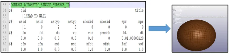
figure 6. Contact Definition in LSPP
7. Creation of Prescribed Motion Set Boundary Card
The objective of this test is to observe the severity of the head after impact with the rigid wall. To make this happens so there is a need to define some motion to the head. This is done using the keyword called Boundary Condition.
Prescribed Motion Set boundary condition is used to define the motion of the head. This is defined to the node-set id 1 and the lcid (1) is used to define the motion of the head.
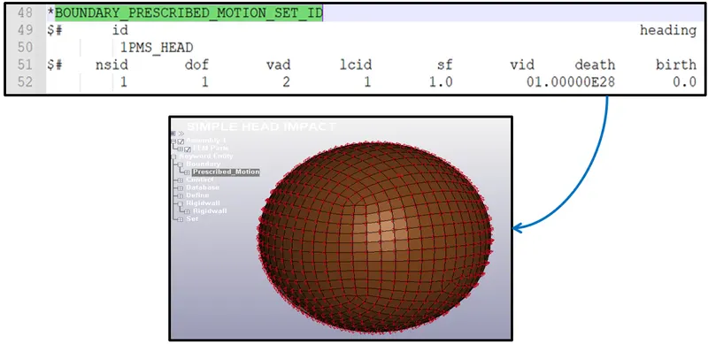
figure 7. Prescribed Motion Definition in LSPP
8. Definition of Displacement Curve
To define the motion of the head the user defines the displacement curve. As shown in the below image the head follows the displacement curve to impact the rigid wall. The same LCID is passed to the Prescribed Motion Set as discussed above.
As we can see that the displacement curve is plotted below and the curve is extended beyond the termination time of 6 ms. This is so because the user wants to capture all the results properly and it is always best practice to extend the curve beyond the termination time.
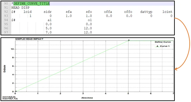
figure 8. Curve Definition in LSPP
9. Definition of Control Termination
Termination time is calculated based on the distance between the rigid wall and the head. This time is defined to stop the simulation after performing the test. Here the user defines the termination time of 6 ms.
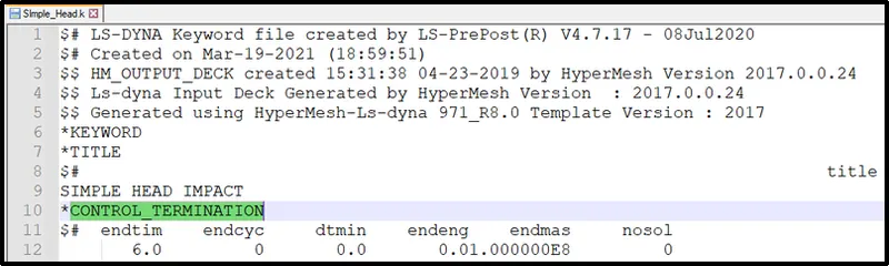
figure 9. Control Termination Definition in LSPP
10. Saving the Keyword File
As a best practice, the keyword file is saved in a specific location without disturbing the base file.
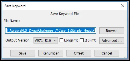
figure 10. Save Keyword File in LSPP
#SOLVING THE MODEL
11. Running the LS Run
The user runs the saved keyword file to plot the result and animation for the test performed.
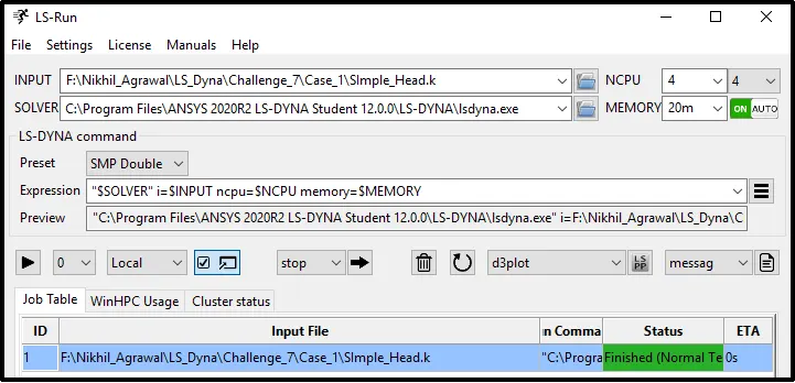
figure 11. LS RUN using LS Manager
#POST-PROCESSING
Simulation Case I
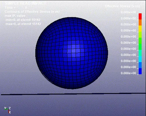
Animation 01. Case I Effective Stress
STRESS - STRAIN PLOT
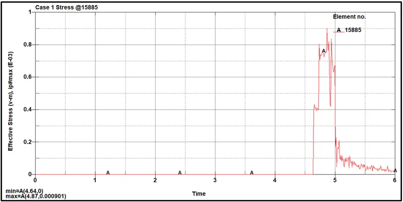
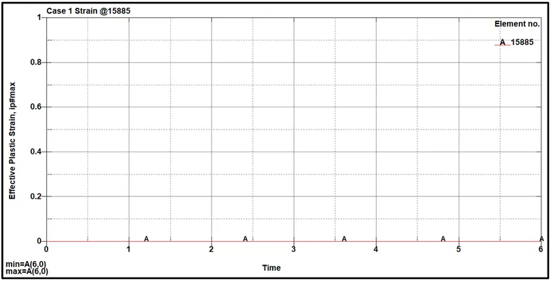
figure 12. - Stress & Strain Plot Case I
Resultant Acceleration Case I
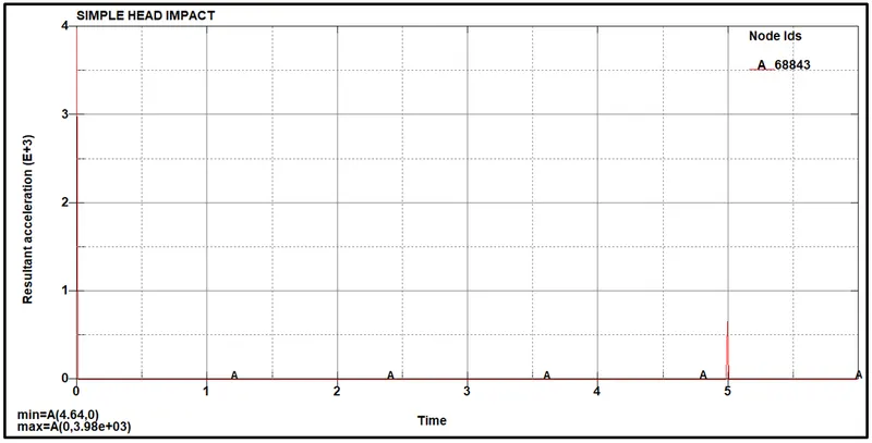
figure 13. - Resultant Acceleration Case I
HIC LS DYNA CASE I
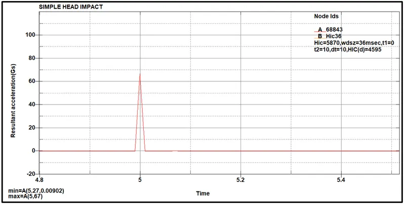
figure 14. - HIC Value Case I
--------------------------------------------------------------------------------------------------------------------------------------------------------------------------------------------------------------------------------------------------------------------------------------------------------
Case II -
Case II is the study is based on the impact of the pedestrian head form with the rigid wall. For this, the user already has the Headform Keyword file available from the LSTC website which is used to simulate case II. This is done by organizing a multi-include file model using the keywords *INCLUDE, *INCLUDE_TRANSFORM,*DEFINE_TRASFORMATION. and the same process is followed as of case I then by to simulate the model.
#SETTING UP THE MODEL
1. DEFINITION OF TRANSFORMATION
*DEFINE_TRANSFORMATION
Purpose: Defined a transformation for the INCLUDE_TRANSFORM keyword option is used to define the transformation of the Head Pedestrian. The *DEFINE_TRANSFORMATION command is defined before the *INCLUDE_TRANSFORM command.
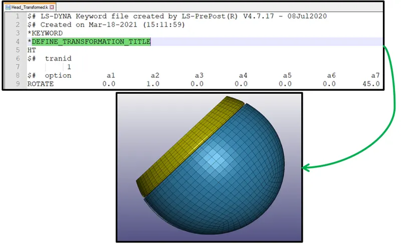
figure 15. - Define Transformation
Here Rotate Option is selected to rotate the pedestrian at an angle equal to 45 degrees.
The function of Rotate is to rotate through an angle (deg), a7, about a line with direction cosines a1, a2, and a3 passing through the point with coordinates a4, a5, and a6.
2. INCLUDE TRANSFORM
Purpose: Includes independent input files containing model data.
Using this keyword the pedestrian headform is included in the main dyn file.
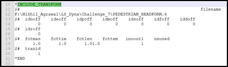
figure 16. - Define Include Transform
3. CREATION RIGID WALL ENTITY
The pedestrian has to impact some entity for observing the effect of impact. For this, the user creates a rigid wall using the entity creation option as shown below.
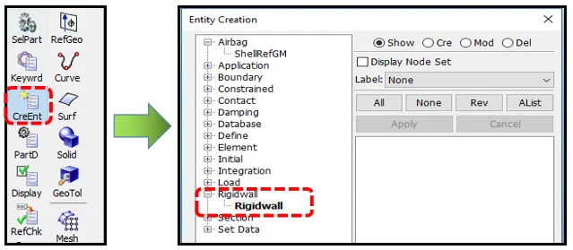
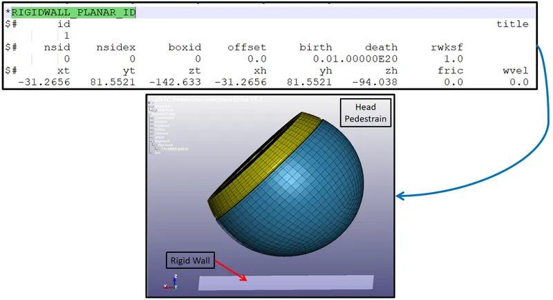
figure 17. - Rigid Wall Creation
4. DEFINITION OF INITIAL VELOCITY
The user defines the initial velocity to the pedestrian so that it will impact the rigid wall.
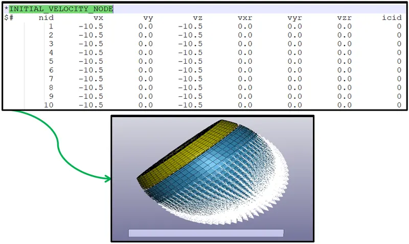
figure 18. - Defining Initial Velocity
5. CREATION OF OUTPUT DATABASE REQUEST
Following output, requests are created using the database keyword to find the results.
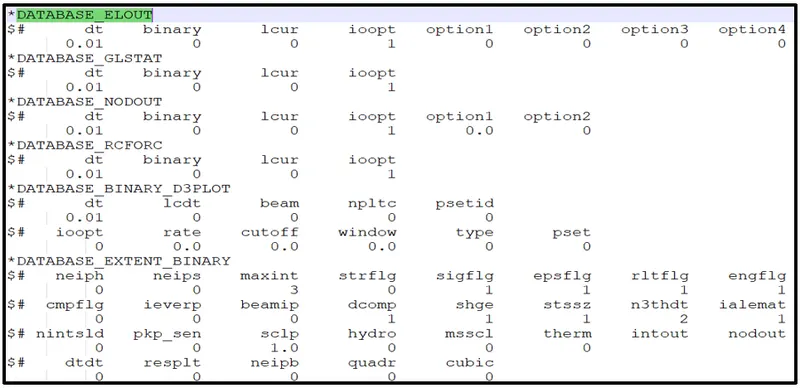
figure 19. - Creation of Output Database Request
6. SAVING THE KEYWORD FILE
The keyword file is saved with the necessary changes made only in the main file with the Dyn extension so that the changes are applied only to the current file.
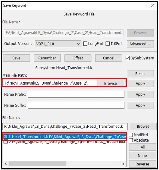
figure 20. - Saving the Keyword File
7. PERFORMING THE LS RUN
The user runs the saved keyword file to plot the result and animation for the test performed.
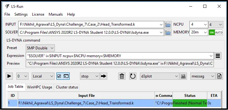
figure 21.- LS RUN Manager Run
#Post-Processing
Simulation Case II
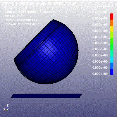
Animation 02. Animated Simulation of Pedestrian Headform Impact on Rigid Wall
STRESS - STRAIN PLOT
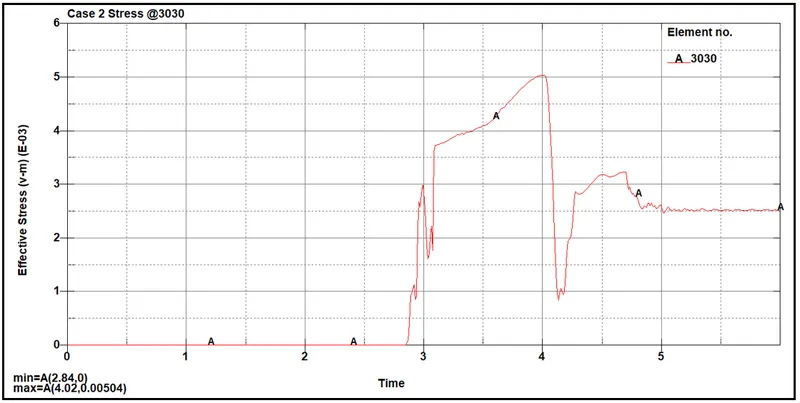
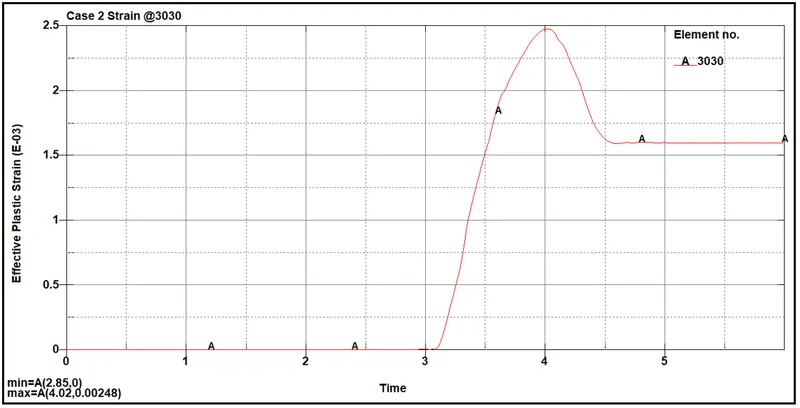
figure 22. - Stress & Strain Plot Case II
Resultant Acceleration Case II
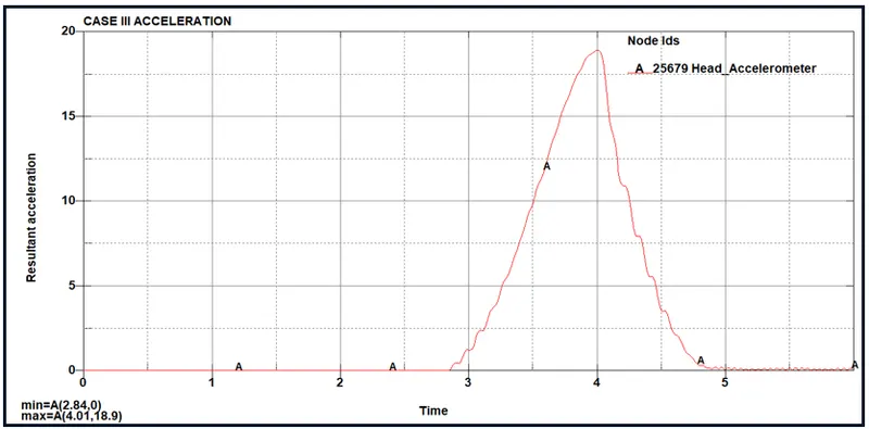
figure 23. - Resultant Acceleration Case II
HIC LS DYNA CASE II
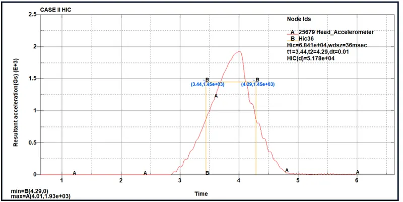
figure 24. - HIC Value Case II
HIC LS DYNA VALUE
From the above graph of resultant acceleration vs time, the user found the value of HIC (Head Injury Coefficient) as 6.841e+04.
Now the user finds the value manually to compare the difference between the software value and hand calculation value.
HIC CALCULATION MANUALLY
`HIC = [(1)/(t2-t1) ∫_(t1)^(t2) a dt]^(2.5) (t2-t1)`
`HIC = [ a_(avg)]^2.5 * (t2-t1)`
From the above, the user sees that,
Averager Acceleration = 1450
t1 = 3.44 ms
t2 = 4.29 ms
Based on this value the HIC obtained is,
`HIC = [(1450)]^2.5 x (4.29-3.441) / 1000`
`HIC = 68051.69`
After observing the manual HIC value and LS DYNA Plot HIC value which is 6.841e+04 the user can say that both the HIC value is matching and the results plotted are correct.
--------------------------------------------------------------------------------------------------------------------------------------------------------------------------------------------------------------------------------------------------------------------------------------------------------
Case III -
Case III is based on the same scenario created in case II but the difference is this time the rigid wall is replaced by the Meshed Hood.
#SETTING UPO THE MODEL
1. ORGANIZE MULTIPLE INCLUDE FILE
The user organizes the multiple keyword files using the Include keyword.
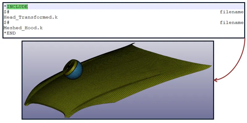
figure 25. - Include File Creation
2. MATERIAL DEFINITION
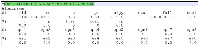
figure 26. - Material Card Definition for Hood
3. CREATED CONTACT DEFINITION
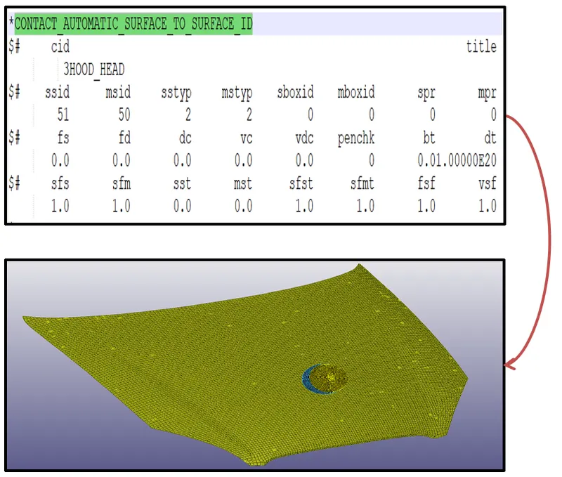
figure 27. - Surface Contact Definition
4. BOUNDARY CONDITION
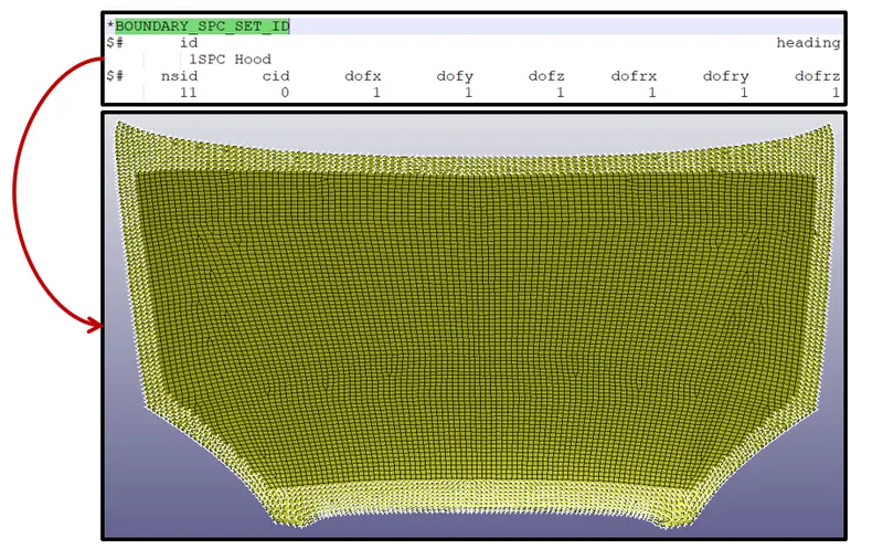
figure 28. - Boundary Condition Definition in LSPP
5. INITIAL VELOCITY
As per the regulation of these tests are usually done at a lower velocity from 20-40 kmph as accidents tend to result in more severe circumstances above these velocities and braking in case of an accident often results in collision at low velocities. The user performs these tests at 40kmph which is equal to 11.11 mm/ms after unit conversion.
To impact the head form at the inclined angle the user perform the hand calculation by solving the vector as below.
Residual Velocity Calculation
Vz = 40sin45 kmph = 34.03 kmph = 9.45 mm/ms
Vx = 40cos45 kmph = 21.01 kmph = 5.83 mm/ms
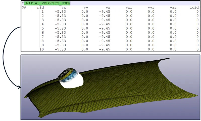
figure 29. - Initial Velocity Definition in LSPP
6. CONTROL TERMINATION

figure 30. Control Termination Definition in LSPP
7. DATABASE REQUEST
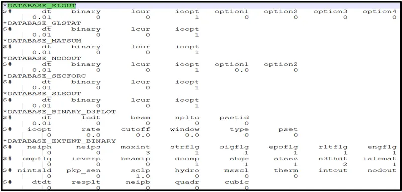
figure 30. Database Output Request in LSPP
#Post-Processing
Simulation Case III
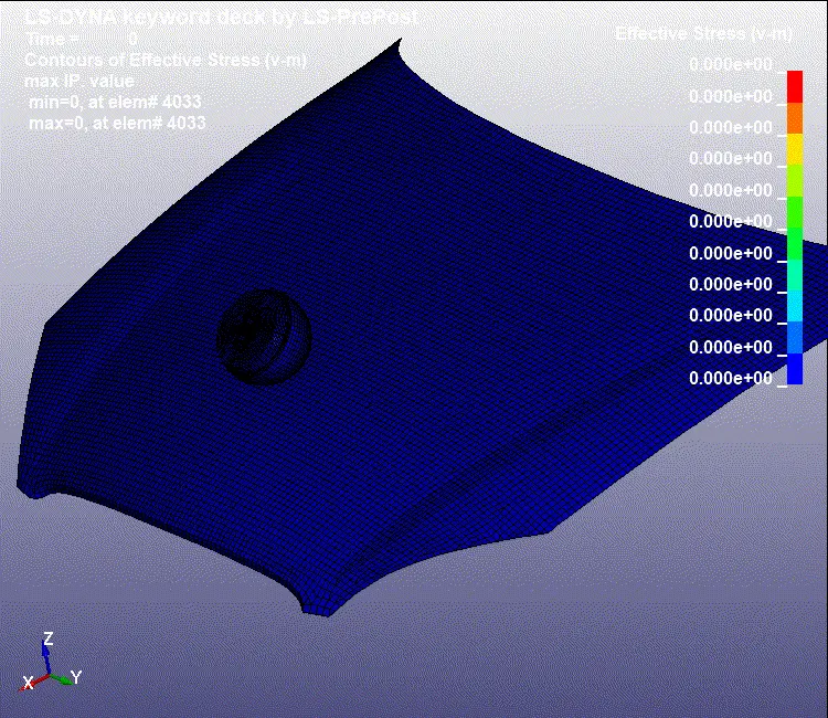
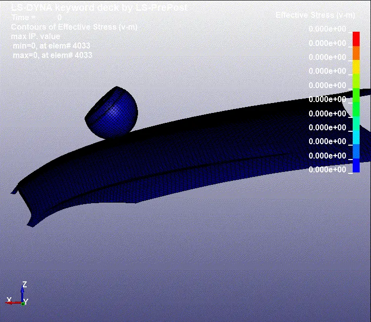
Animation 03. - Animated Simulated of Pedestrian Headform Impact on Meshed Hood
VON-MISES STRESS
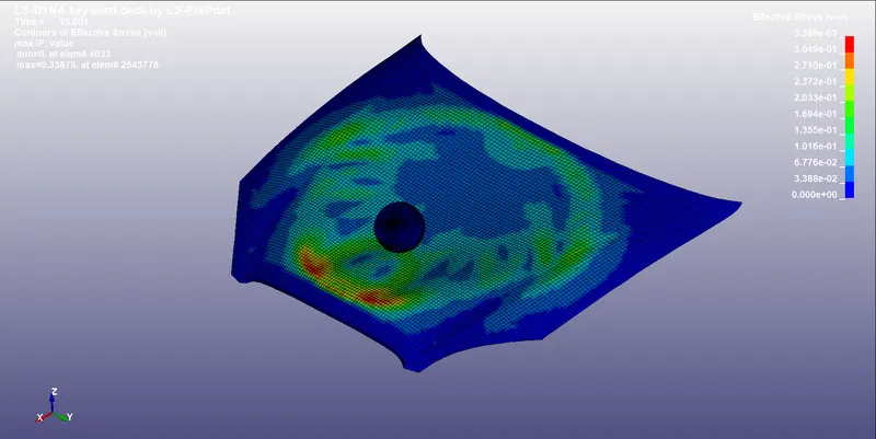
figure - Effective Stress due to impact
EFFECTIVE PLASTIC STRAIN
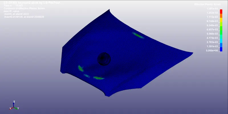
figure - Effective Strain due to impact
STRESS - STRAIN PLOT
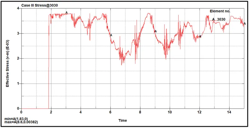
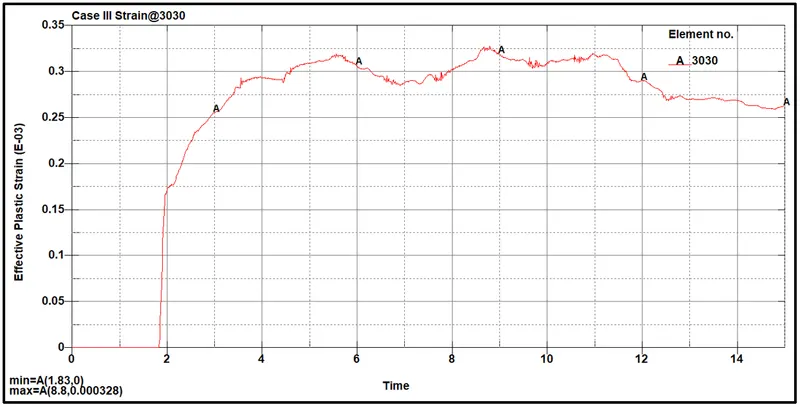
figure - Stress & Strain Plot Case III
Resultant Acceleration Case III
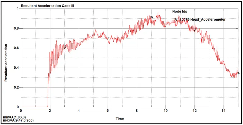
figure - Resultant Acceleration Case III
HIC LS DYNA CASE III
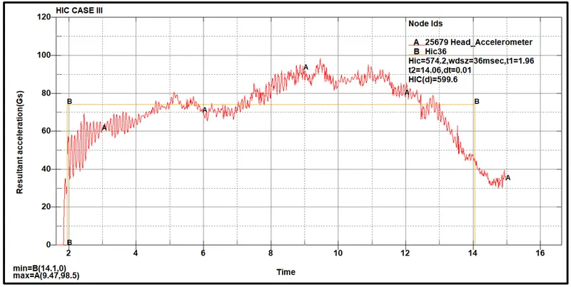
figure - HIC Value Case III
HIC LS DYNA VALUE
From the above graph of resultant acceleration vs time, the user found the value of HIC (Head Injury Coefficient) as 565.2.
Now the user finds the value manually to compare the difference between the software value and hand calculation value.
HIC CALCULATION MANUALLY
`HIC = [(1)/(t2-t1) ∫_(t1)^(t2) a dt]^(2.5) (t2-t1)`
`HIC = [ a_(avg)]^2.5 * (t2-t1)`
From the above, the user sees that,
Averager Acceleration = 86
t1 = 1.96 ms
t2 = 14.2 ms
Based on this value the HIC obtained is,
`HIC = [(74.2)]^2.5 x (12.14) / 1000`
`HIC = 575.74`
After observing the manual HIC value and LS DYNA Plot HIC value which is 575.2 the user can say that both the HIC value is matching and the results plotted are correct.
CONCLUSION -
- Hand on work experience in LS DYNA with the industry-relevant complicated model.
- Manual calculation of the HIC (Head Injury Coefficient).