Week-7 Head Impact
Aim:
To perform head Impact simulation and calculate HIC values for 3 cases
- Simple Head with rigid wall
- Headform rotated with rigid wall
- Headform rotated with meshed Hood
Case setup:
There are 3 files provided in the model - Simple head, headform and meshed Hood. These files should not be edited and should be included in our model using
keyword -> Include (or)
keyword -> Include -> Transform (To invoke transformation)
keyword -> Define -> Transformation (to rotate the headform by 45 degrees)
We are following mm, ms, kg units in this assignment
Section
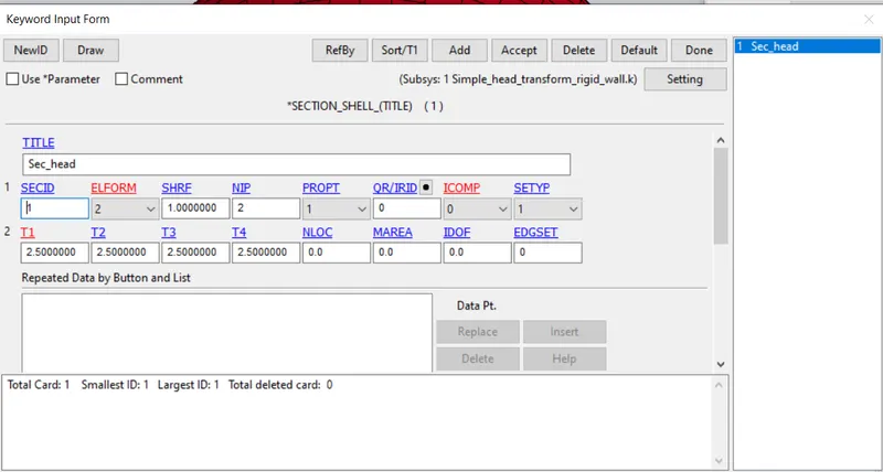
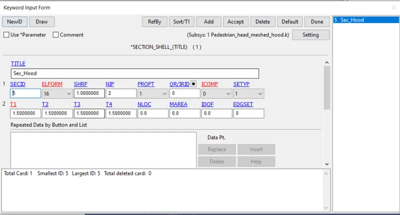
The simple head and Hood are shell components. So a shell section is created with 2.5mm thickness and ELFORM 2 for simple head and shell thickness of 1.5mm thickness and ELFORM 16 for Hood. Headform already has section properties assigned so no need to create one.
Material
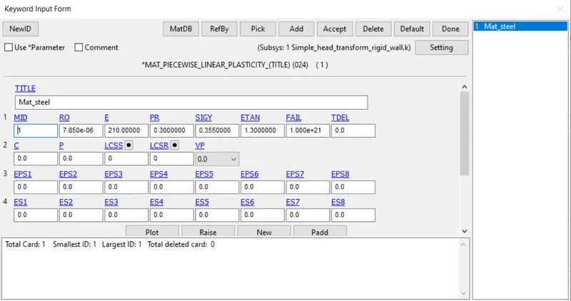
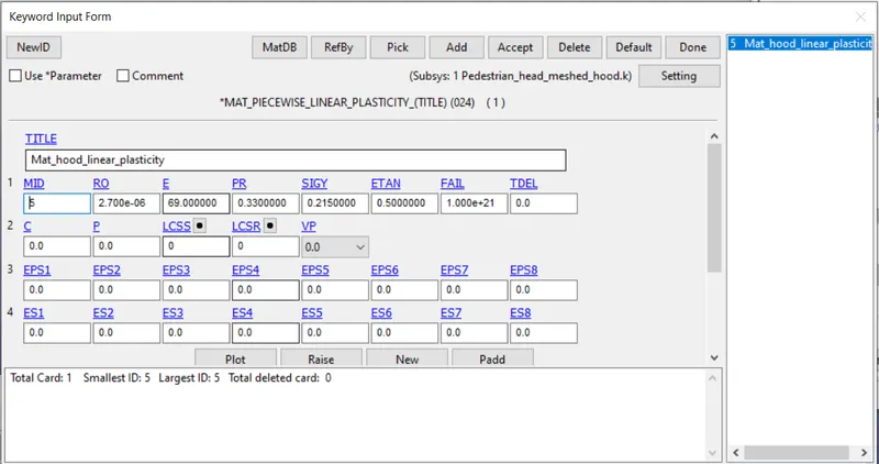
A steel material is assigneed for the simple head. Headform already has material properties assigned so no need to create one. For the meshed hood, Aluminium properties are provided.
Assign section and mat properties to part
The material and section cards created are now assigned to the respective Part
create rigid wall
A rigid wall is created underneath the simple head using
Create entity -> Rigidwall -> Rigidwall -> Create (Using planar and 1N+L define vector with one point and normal)
Now open
Keyword -> Rigidwall -> Planar
and input 0 in Nodeset ID NSID which makes all nodes in the model as slave nodes
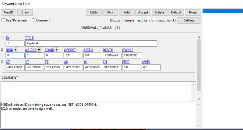
contacts
Automatic Single surface is created to avoid penetrations during imact. Slave set ID value is given as 0 to include all surfaces in the salve set 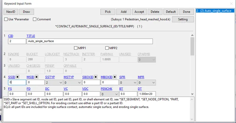
Control
Termination time is given as 20ms
Initial velocity
For the Simple head case, Intitial velocity of 40kmph=11.11m/s is imparted to the model in the negative z direction using
Initial -> velocity
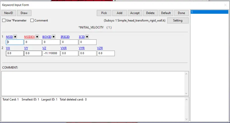
For the Headform with meshed hood, velocity of 40kmph of the headform is resolved into 2 components along negative z (-8.510m/s) and negative x direction (-7.142m/s)
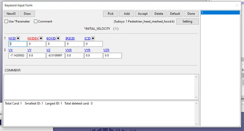
Boundary
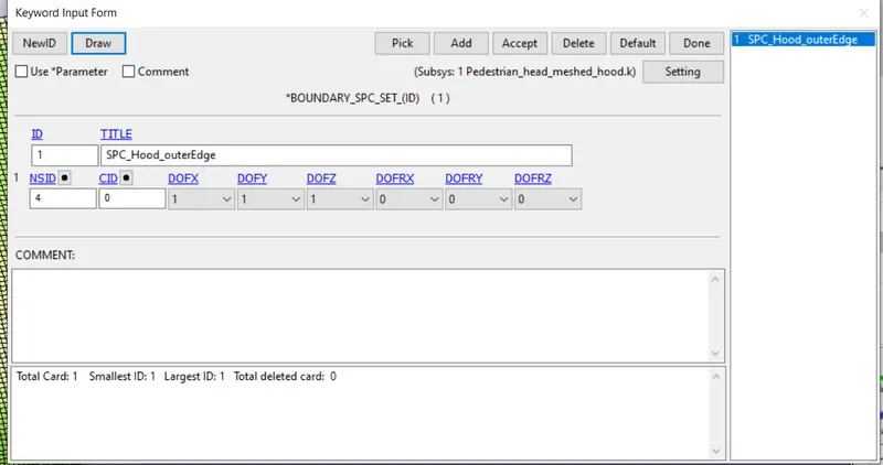
For the meshed hood model, a nodeset is created with all the outer edge nodes of the hood. An SPC set is created and all translational DOF are constrained
Database
ASCII_option: GLSTAT, NODOUT, RWFORC
Binary D3 Plot: DT of 0.5ms is provided
History node: A node in the shell is selected to get information about the node in the NODOUT file
Extent Binary: STRFLG is changed to 011 to get strain data
Post Processessing:
Stress Plots
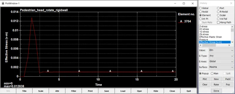
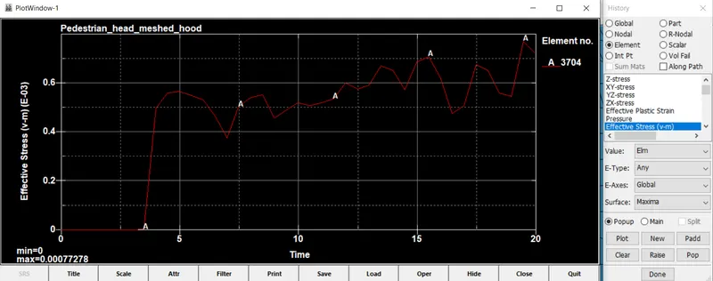
In the forst case, as the wall is rigid and cant absorb energy from the impacting headform, the headform experience a large amount of stress compared to the fleible hood. As the hood absorbs the crash energy from the Impacting headform, stores it as potential energy while getting crushed and slows down the headform. Henceforth the headform experiences less stress with the hood.
Strain plots
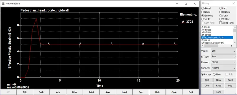
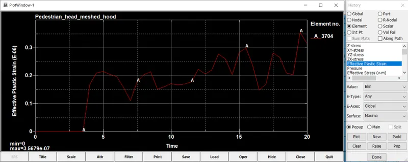
As the hood is flexible and deformable, it absorbs energy from the impacting headform. Hence, the strain value is lesser in the hood model compared to the rigidwall model.
Acceleration plot with HIC
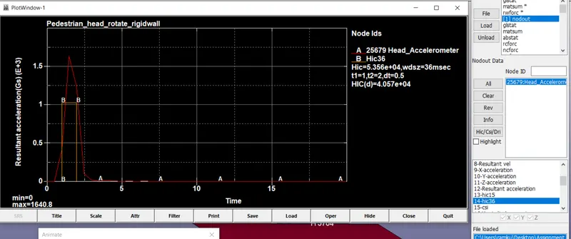
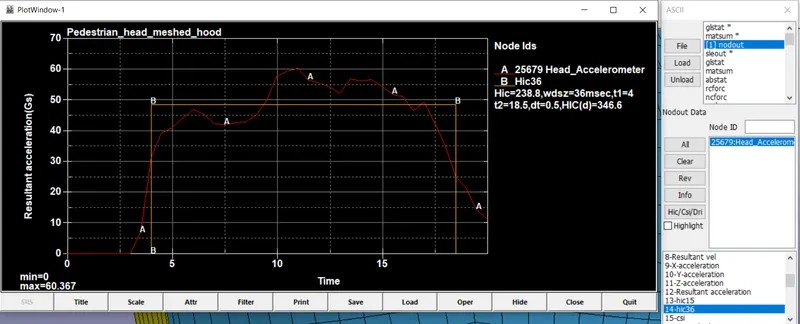
As it can be seen, HIC value is very less in the hood model compared to the rigid wall model which indicates there is less probability of severe damage to head with the hood model.
Conclusion:
All the results shows flexible hood is safer to pedestrian head than the rigidwall.
Hence the hood should be designed in such a way to absorb as much energy as possible from the pedestrian head to minimize the risk of severe damage. Below the hood lies the rigid engine. So the hood should not designed with so much compliance as well.