Week-7 Head Impact
Head Impact
Pedestrian safety simulation is a part of vehicle safety engineering.this study focus on car and pedestrian on car and pedestrian interaction.the main focus of this is to reduce the pedestrian injury in case of an accident (head,injury leg etc). usually these tests are performed in the lower velocity range from 20-40kmph.HIC (head injury criteria/coefficient) is a measure of the likelihood of the head injury caused due to the impact after an accident, this is basically a measure of average acceleration during a small interval of the crash.
OBJECTIVE
To perform head impact simulation and calculate the HIC (head injury criteria/coefficient) value in the Ls-Prepost.
In this study the simple head impact on the rigid wall is studied at first.then the impact of given headform model with the rigid body is studied future followed by headform impact on the hood. Important results such as stress strain system energy ,HIC values are derived in post-processing.
Head Injury Criteria (HIC)
The head Head Injury Criteria (HIC) is a measure of the like hood of head injury.arising from an impact.the HIC can be used to asses safety-related to vehicles personal protective gear and sports equipment.
Normally the variable is derived from the measurements of an accelerometer mounted at the center of mass of as head when the dummy is exposed to crash forces.

Where t1 and t2 are the initial times (in seconds) chosen to maximize HIC and acceleration a is measured in g. the time duration t2-t1 is limited to a maximum value of 36ms usually 15ms.
This means that the HIC includes the effects of head acceleration and the duration of the acceleration. Large acceleration may be tolerated for very short times.
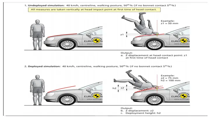
head impact tests are performed with 3 different cases.
- simple head impact with a rigid wall.
- pedestrian head impact with a rigid wall.
- pedestrian head impact with the hood.
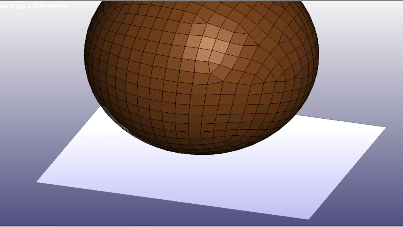
Case 1 (simple head impact with a rigid wall ).
- A simple head geometry is given with a problem statement. This model has meshed only shell elements. In this case ,the model is impacted on rigid wall. The rigid wall is created by using following step.
Create enity >rigid all > planer> 1N+NL > for Z orientation.the rigid wall is created 10 mm away from the bottom most node. In this case the unit system is taken kg/mm/ms is used.
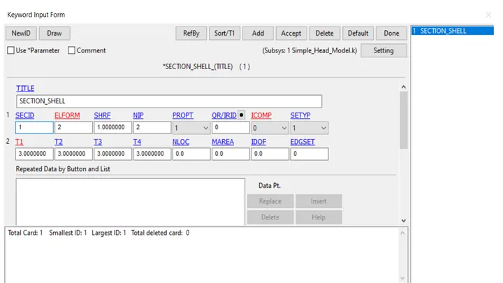
- The section properties for the simple head are given by using *SECTION_SHELL card. All the properties are set to default and a thickness of 1.0mm is assigned to the shell element.
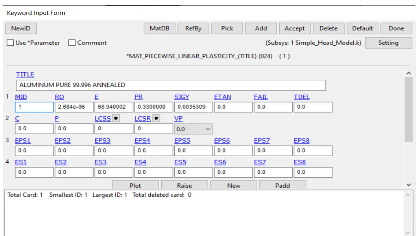
- The material card is used MAT_24 piecewise linear plasticity and assigning the aluminum material.
The geometry is assumed to have 40 kmph velocity along the traveling path at 45 degrees along -z axis . in this case the geometry is circular so ,the transform option is not working. The geometry is traveling 45kmph velocity into -z direction so the velocity is converted into KMPH into m/s. the velocity is assigned 12.5 m/s in the X direction and -12.5 m/s in -z direction.automatic single surface contact is defined for this simulation ,only the slave segment definition is reqired for this contact type.the simple head geometry is assigned as the slave segment and the master segment column is kept empty.
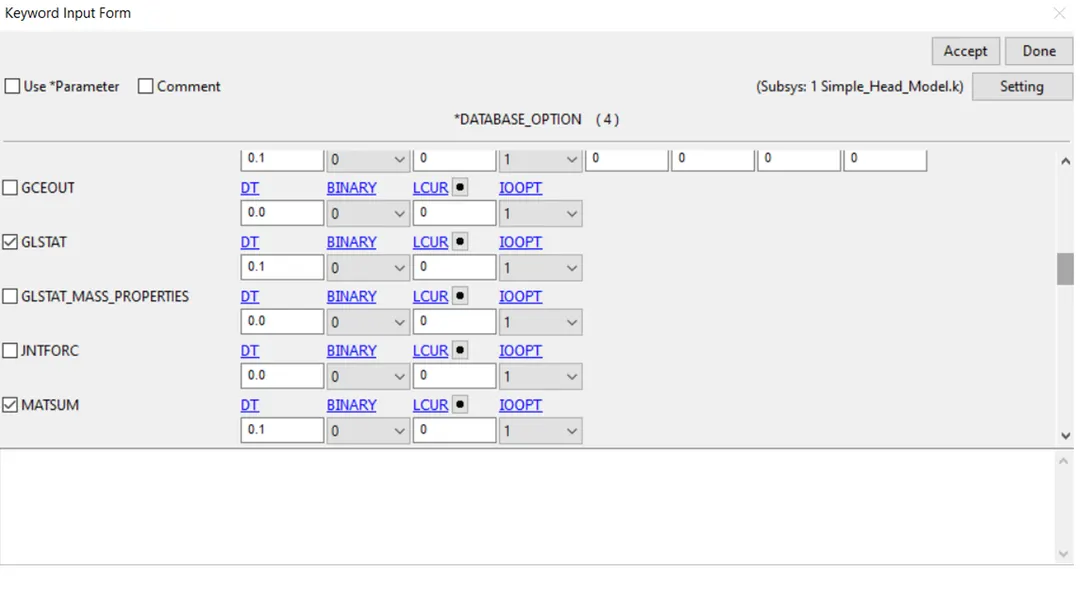
The HIC value is extracted through the NODOUT card in *DATABASE_ASCII ption. But for extracting a node ststistics ,the desired node should be selected. Here the bottom most node is selected for extracting results. The DATABASE_HISTORY_NODE card used to select the bottom-most node. Binary D3plot is activated database section to get the final impacrt animation.
result case 1
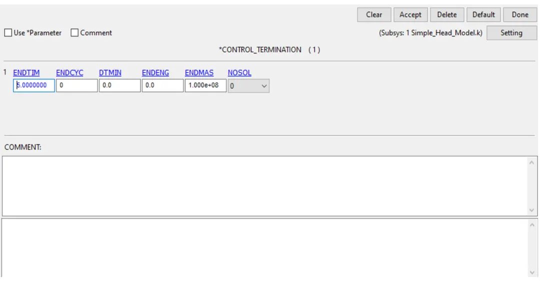
The termination time for the problem is defined by control_termination card.the distance between the head geometry and the rigid wall is calculated and the approximate time taken to hit the rigid wall and some additional time after the impact is calculated. The cumulative time 10ms is defined as termination time in the card.
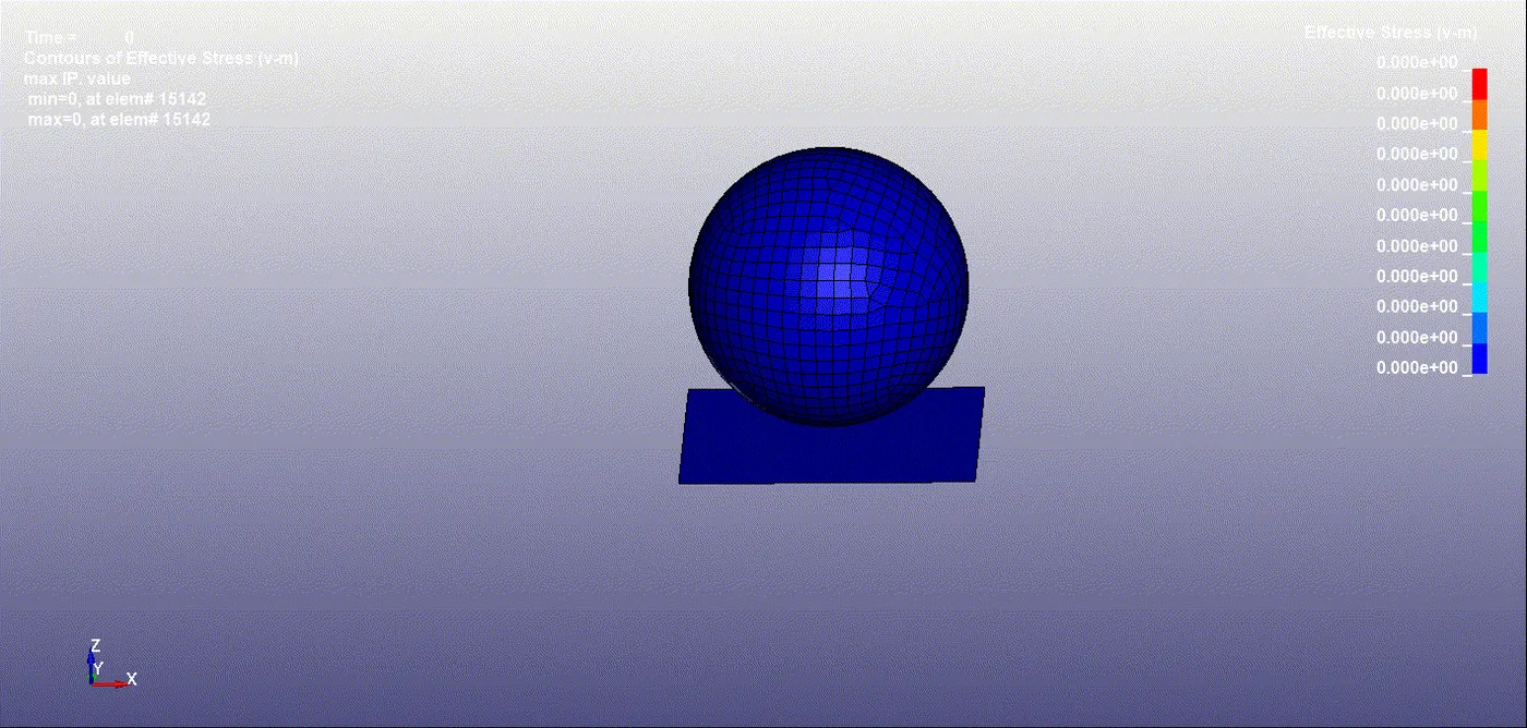
- The stress behaviour of simple head after the impact the stress values are higher at the instant of impact and reduce with fluctuations after the impact as the material is purely elastic.
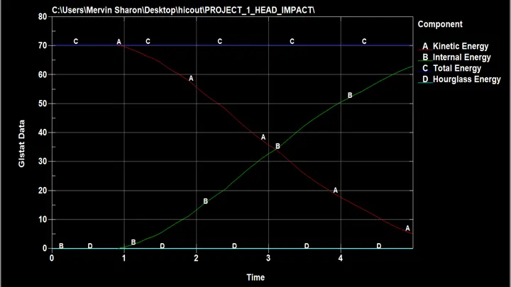
- The energy statistics are extracted through depicts the energy plot for a simple head impact on rigid wall simulation. It is visible that the kinetic energy decreases and internal energy increases at the instant of impact.this is due to the reduction of the velocity during impact.the simple head geometry being elastic material bounces back without major loss of energy and attains velocity in other direction.this causes again increase in kinetic energy and a decrease in internal energy future. The internal energy remains constant and the hourglass energy is also under desired limits.
Case 2. (pedestrian head impact with a rigid wall).
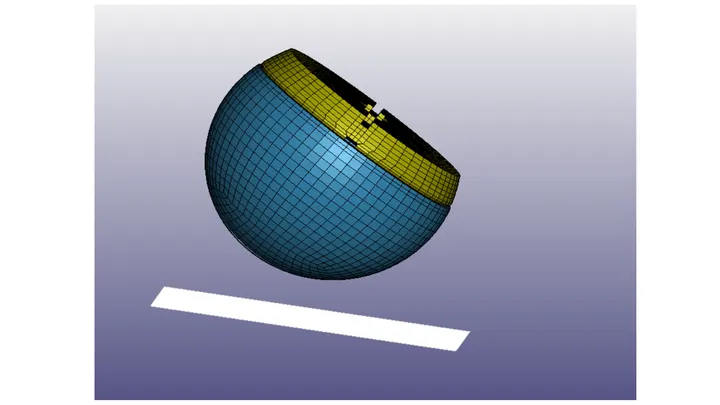
- The pedestrian child head model is made to hit the rigid wall in case 2. Open the pedestrian headform.k file in Ls-Prepost. The FE model consists of 4 parts Skin,an ogden (77_0) material and Skull ,Acceleration block , backplate are rigid (20) materials.
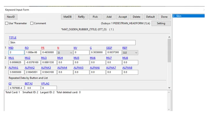
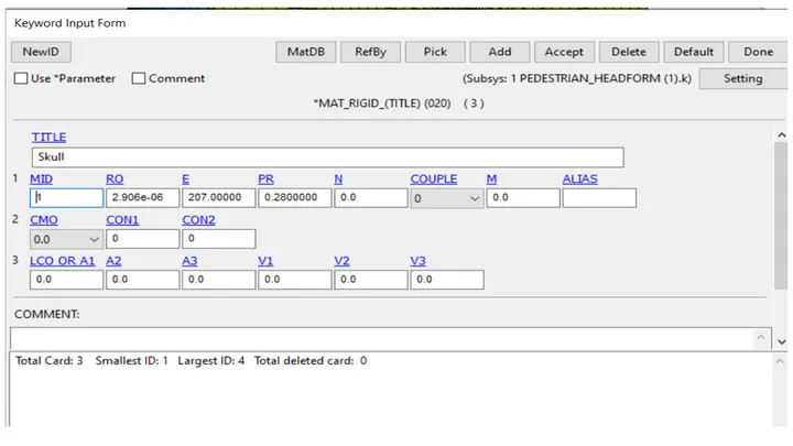
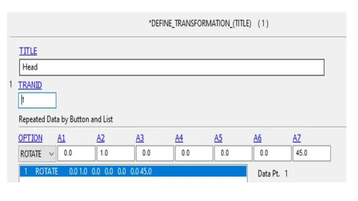
In this case a child -head model is been provided so we would be replacing it with the spherical ball used in the above mentioned simulation.now we don’t want the original mode to change in the .k file provided but I ant to incline the head model at 45 degrees to the rigid wall because generally the angle of head hitting the car hood in at an angle of (35-75 deg). So in order to change the angle of the model I used DEFINE_TRANSFORMATION the details of which are mentioned below ,in this case I can define angle is 22.5 degree and used *INCLUDE_TRANSFORM option twice.
Now as mentioned in the above paragraph I don’t want to save these changes in the original model so I use *INCLUDE_TRANSFORM in order to call the rotated in a .k file and perform the simulation their with the wall.
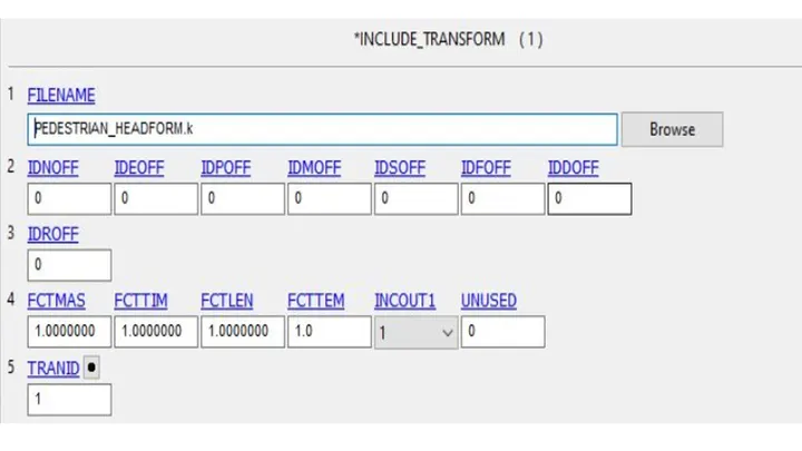
The headframe section was selected as a solid section.
The other keyword such as *automatic_single_surface ,control_termination and ascii outputs GLSTAT ,MATSUM,NODOUT,RCFORCE was kept the same as used in simulation.
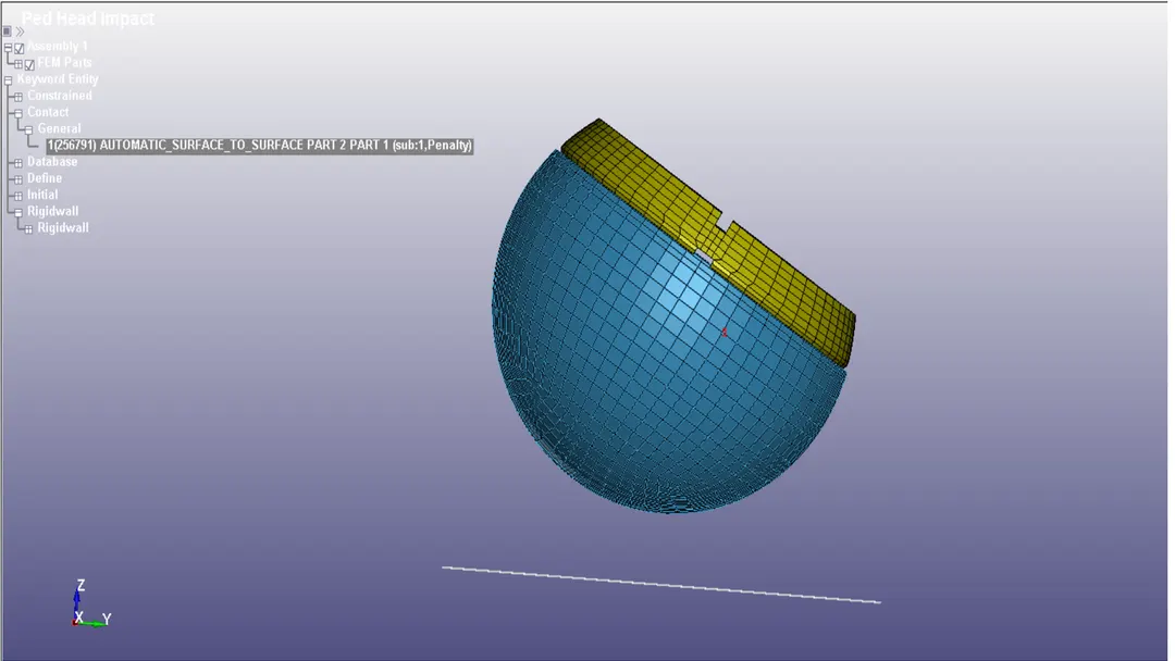
contact
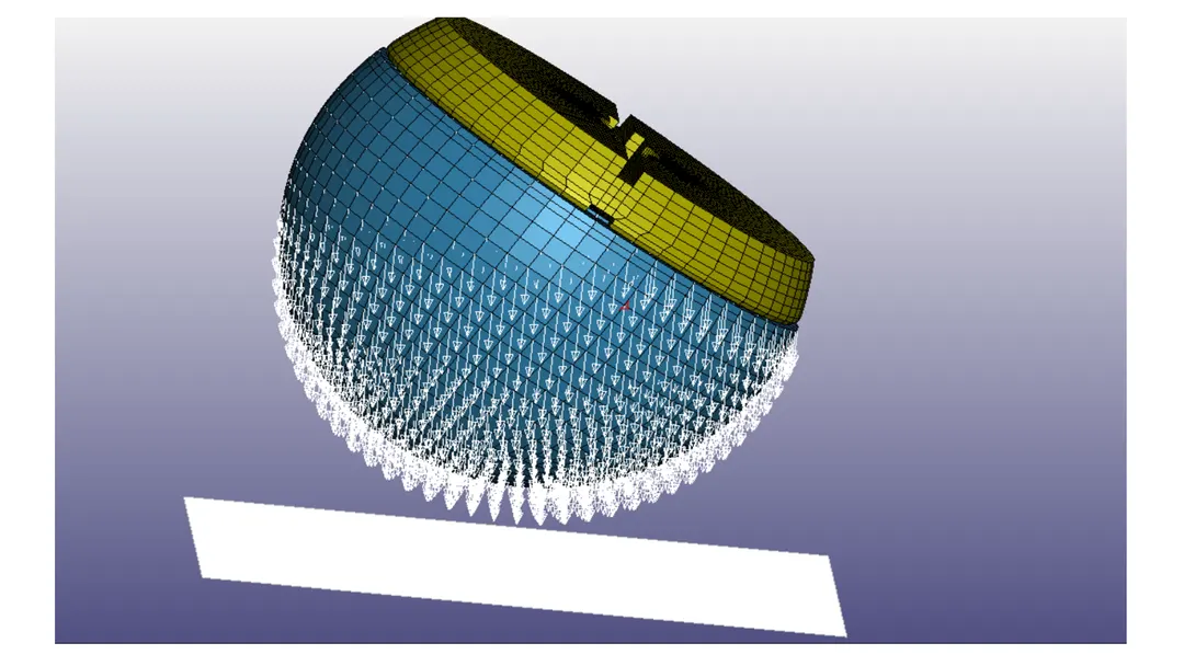
initial velocity
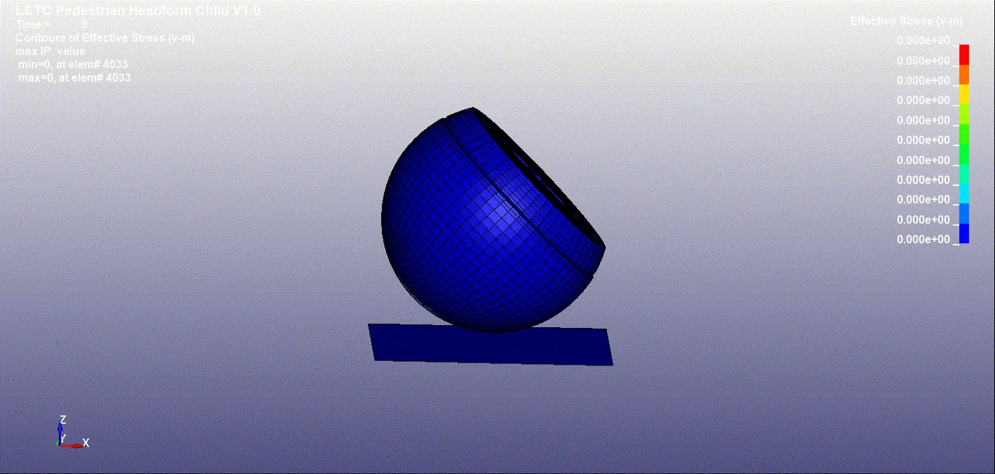
There is no significant deformation in the simple head geometry the fig depicts stress behaviour in headform geometry after the impact the material properties for this geometry are pre-defined and different from the simple head so it shows different behaviour.
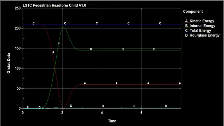
The energy plot for headform impact on a rigid wall. The kinetic and internal energy show similar behaviour during impact.but as the headform is modelled with hyper-elastic material and rigid body there is a gradual change in the energies after impact compared to simple head case. Some of the energy is gone in deformation caused due to impact.hourglass energy is under desired limits for this case too. We can see the percentage increase in mass is also very low and hence there is no addition of artificial mass which may cause non-physical behaviour.
Case 3 (pedestrian head impact with the hood ).
- the pedestrian child head model is made to hit a car hood. The meshed car hood is aluminum of thickness 2mm and ELFORM 16(fully integrated) which is to be replaced at the same place of rigid wall.
- The pedestrian head is included in the model and trainsformed to desired angle (45 deg) using include_transform_define transformation keywords.
- Create SPC boundary condition and fix all DOFs at the edge nodes of the meshed car hood so the hood remains constrained in all direction.
- Create initial velocity of 40Kmph (11.11 mm/ms) in direction -z on all nodes of the pedestrian child head FE model.
- Create automatic single surface contact with slave nodes as the meshed hood whild the skin and skull part are assigned as master.
- Create control> energy ,hourglass and termination time of 30ms.
- Create database >ASCII with ELEOUT ,MATSUM,GLSTAT,NODOUT,SLEOUT,Binary d3plot,extend binary.
- Save and run simulation in LS -dyna manager.
Result Case 3
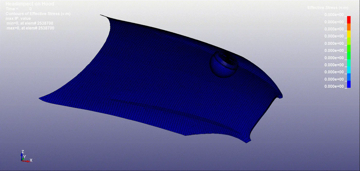
There is significant deformation in the geometry after the impact shows that the hood deforms after the impact and there is less deformation in the head compared to the second case. This is because of the elastoplastic material which has been defined to the hood this material tends to deform elastically till the yield point and then deform plastically after that.
-
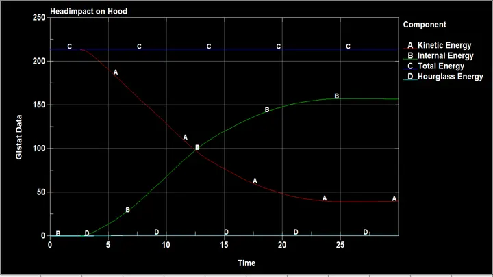
The enrgy plot for headform impact on a rigid wall. The kinetic and internal energy show similar behaviour during impact. But as the headform is modelled with hyper-elastic material and rigid body there is a gradual change in the energies after impact compared to simple head impact case. Some of the energy is gone in deformation caused due to impact.hourglass energy desired limits for this case too. We can see the percentage increase in masss is also very low and hence there is no addition of artificial mass which may cause non-physical behaviour.
HIC 36
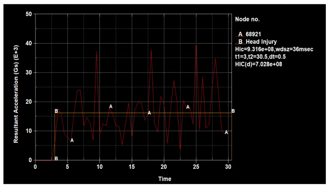
HIC value is generally derived from the accelerometer mounted at the centre of mass of the crash test dummy. For the simple head impact test a node on the outer surface was manually selected for result extraction .HIC 36 value is calculated in Ls-prepost and basically measured for a time interval less than 36ms duration. It can be can be seen that the HIC 36 value for simple head impact whereas it can be seen the HIC 36 value for head form impact is the hic 36 value for headform impact is measured from an accelerometer place in the geometry .from both the figure it can be seen,the resultant acceleration is increased and then decreased after the impact because the body comes to halt and again bounces back. Shows the hic 36 value for head and hood impact. The calculated value from ls-prepost is . if the time interval used to calculate the HIC value is shorter than 15 ms both HIC 15 and HIC 36 have the same value. If the time interval is larger than 15 ms then HIC 36IS HIGHER.
case 1
case 2
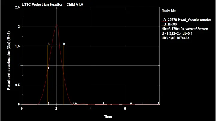
- HIC value is which is less than NCAP recommended value ( 650 )
case3
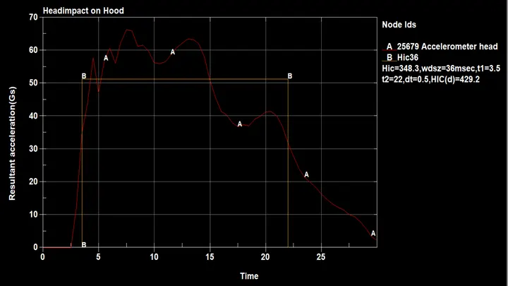
- From the graph we can notice that the chance of the injury are low but we cannot assure the time about the injury just by seeing HIC value .
The value of HIC is which is less than 650 so that we assume that the head will be safe from injury.
Conclusion
The head impact simulation is performed with all relevant post-processing results.
Case 1 gives an idea of a general analysis setup.this analysis is performed with random material properties and case setup is made to perform future analysis.the simple head geometry does not deform and has negligible strain values after impact.this case has the highest HIC value due to the harder head and rigid wall.
Case 2 -gives a brief idea about head impact with the rigid wall. This impact with a rigid wall is serve and it deforms heaform geometry. Higher plastic deformation is seen after the impact. The HIC values are lower case 1 but higher than 3. This is because of different hadform material properties compared to case 1.
Case 3 – gives an idea of the actual head impact on car hood. The hood being a deformable body with elastoplastic material properties deforms during impact. The effect is less severe comparatively and HIC values are low for this case compared to case 1 and case 2. This signifies that the probability of head injury in this particular case is low as compared to case 1 and case 2.
G link
https://drive.google.com/file/d/1ZMVcOjZHli3ESpziSW9iFhgq3sjosHnt/view?usp=sharing