Pedestrian Head Impact Simulation
Aim
Using Ls dyna do the Pedestrian Impact simulation and check for the HIC value of the impact and thereby optimizing the hood model to be safer for the pedestrians.
OBJECTIVE
We need to do the impact simulation of the Hybrid III dummy head model into te hood of an automobile to simulate the real life pedestrian impact situation to evaluate the HIC value of the impact.Free motion head form is the head model of a Hybrid III dummy which is recognized by NHTSA for evaluating head impact protection against vehicle interior components. The nose and other features of the hybrid III dummy headare removed to prevent their interference with the trim component during testing. Physical model of free motion headform (FMH) mainly consists of an outer rubber skin attached firmly over an inner aluminium skull. At the centre ofgravity of FMH, accelerometers are placed to record the acceleration used to calculate the HIC.From the HIC value we can determine the amount of innury the pedestrian may get suffered while this particular hood fixed automobile hots on a pedestrian.Thereby we can make desicions regarding any change in design is needed to be made to
Case Setup
Here have a headfoam model which is basically provided some organisations.We need to use the head foam to smiluate the pedestrian head impact on a hood model given.Since this is a little complex simulation involving the hyperleastic material which has the non linearity in it .So we will be doing this problem step by step,we will add the complexity gradually.because this helps to understand where the things gone wrong.So we firststart witha simple head model in shape of a sphere.We can define a rigidwall and we can make it hit to the rigidwall and we can simulate it to see the deformation and HIC values.
For that first open the simple head model in Ls dyna .Then define the rigid wall by using create entity tool.While creating the rigid wall make sure the rigid wall is having normal in the direction opposite to that of head movement.Using the Intial velocity card we can define the velocity of the simple head .
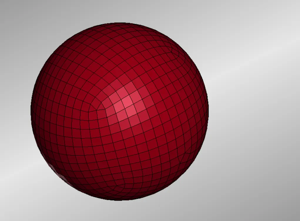
Fig 1 Simple Head Model
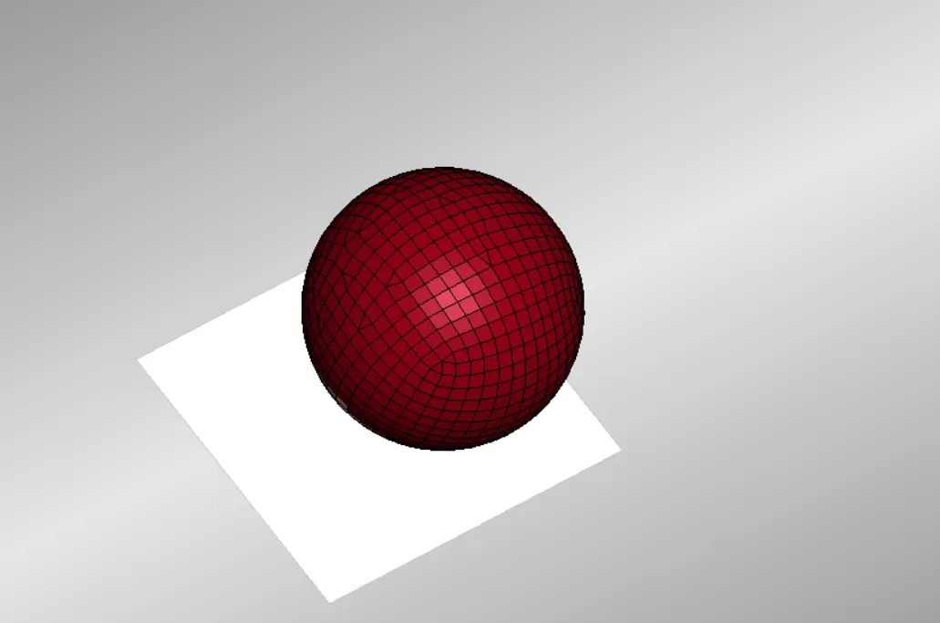
Fig 2 Simple Head Model with Rigid Wall
In addition to this we don't want the ball surfaces to get penetrated into each other so we need to define a self contact in the head.this contact can be defined using AUTOMATIC SINGLE SURFACE Contact.here we define only the slave part.In the SSID we define the head part set by defining SSTYP as 2.
Usual card such as control termination and database d3plot are to be defined.Then we try running it to ensure the proper running of the deck created
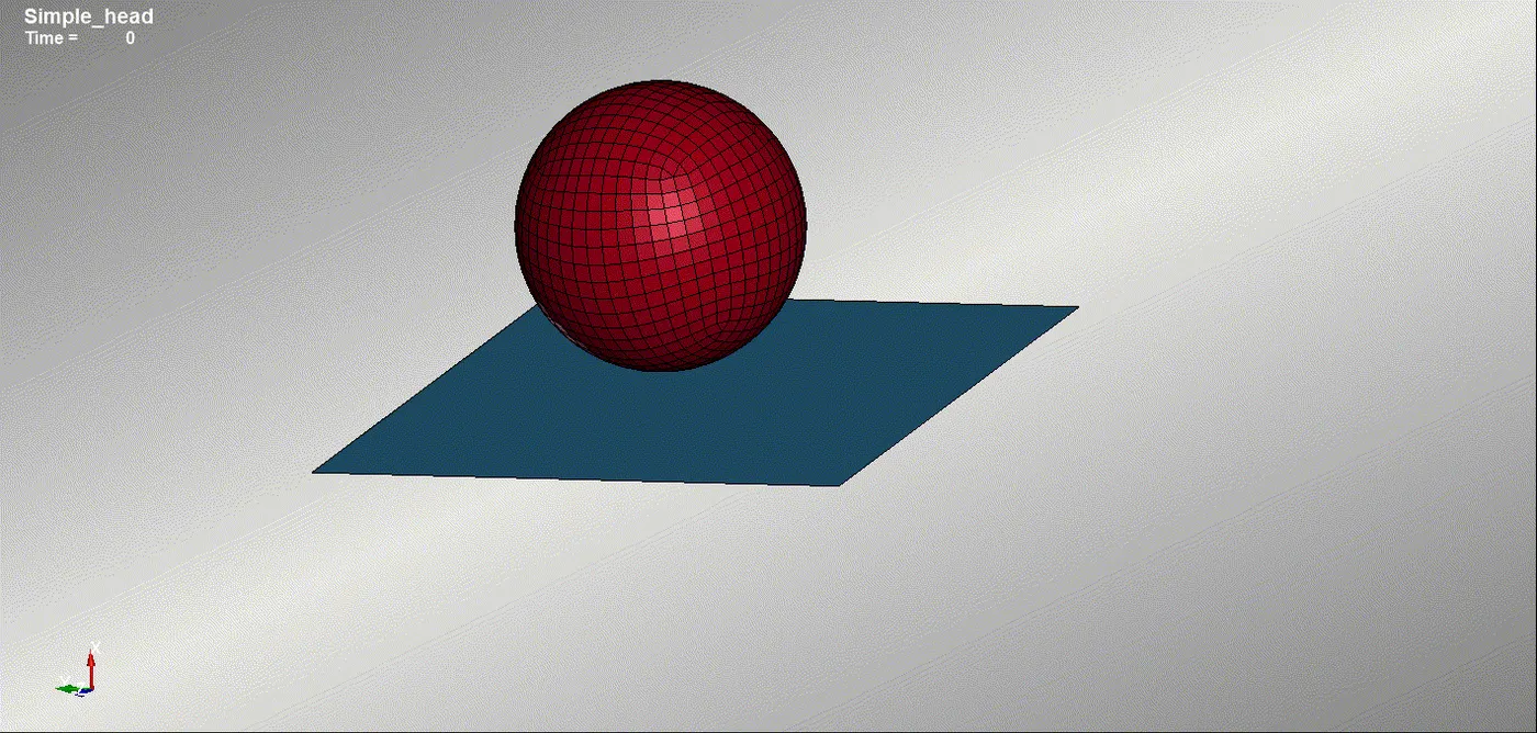
Fig 3 D3Plot of Simple Head impacting on Rigid Wall
So we ensure our head model is making the proper movement as we intended.
Now we can move on to use the proper Head Foam instead of the Simple head model. For this we need to use the include card to include the head foam keyword file.But we can see the pedestrian head foam model is alligned with the normal axis.
We can open a new ls prepost and save the file as DYN file. This as new file which is the Main Keyword file of the simulation prefferably as DYN file. So we can save it as MAIN.DYN .Then open the pedestrian head file using the include transform card.
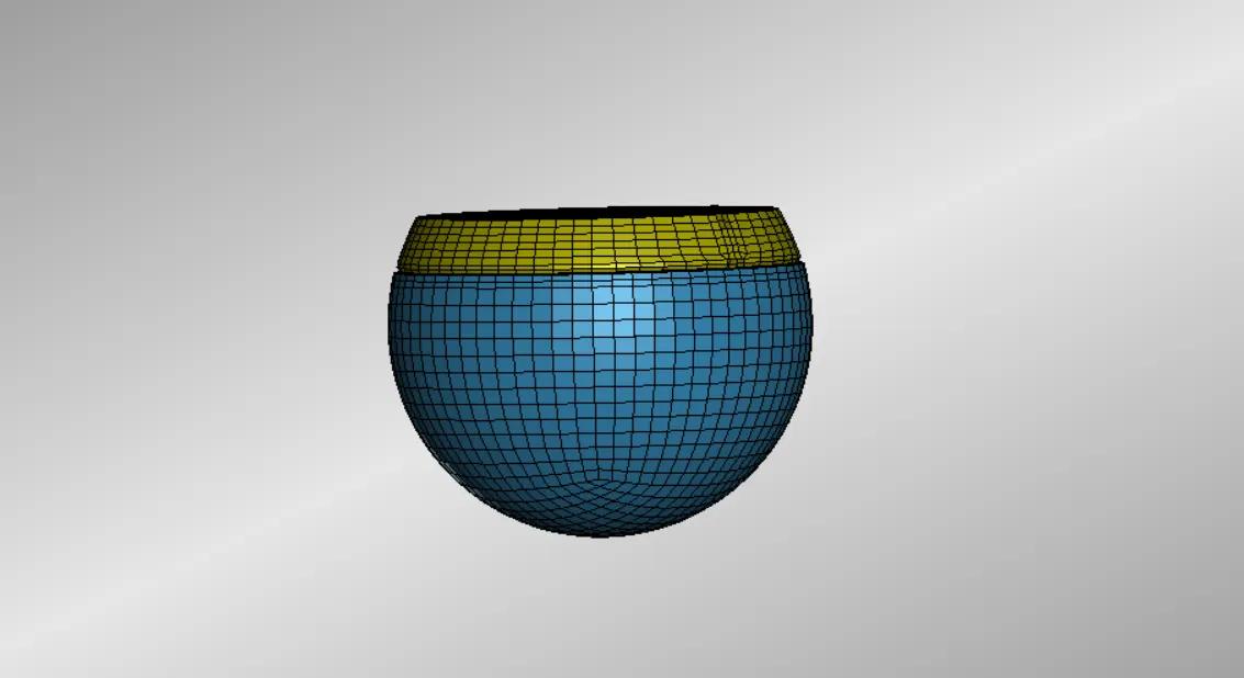
Fig 4 Pedestrian Head Foam Model
But we need the head form to hit the rigidwall at an angle of 35 - 40 degree angle, since the pedetrain when hit by the car the pedestrain will head will hit the bonnet of car at an angle of that range.So when we need to simulate the same thing we need to tilt the head foam by 35 degree .This can be done using the Include_transform keyword. Before that for the include transform keyword require a transform to be defined.
For that use the define_transform card to define the transform.In define transform card we need to set the OPTION as Rotate and there is parametrs from A1,A2,A3....A7.First three are basically the direction cosines in the all the three axis.And the next three is the indicates the x coordinates,Y cocordinates, z cocordinates respectively.Then A7 is the option to imapart rotation to include file.Since we need to rotate the foam model in Y axis, we need to give direction cosine in Y axis as 1 and rest every axis as zro direction cosine.Then w can give th rotation angle as 35 degree in A7.This create the transform card.
But to pull in the file into the Ls PrePost we need to use the INCLUDE card.But since we need to make transformation for the pedestrian Head foam model. we meed to use th Include_transform Card.in include transform card we need to define the headfoam keyword file and define the TRANS ID and save it.Then save the this as new file which is the Main Keyword file of the simulation prefferably as DYN file. So we can save it as MAIN.DYN .
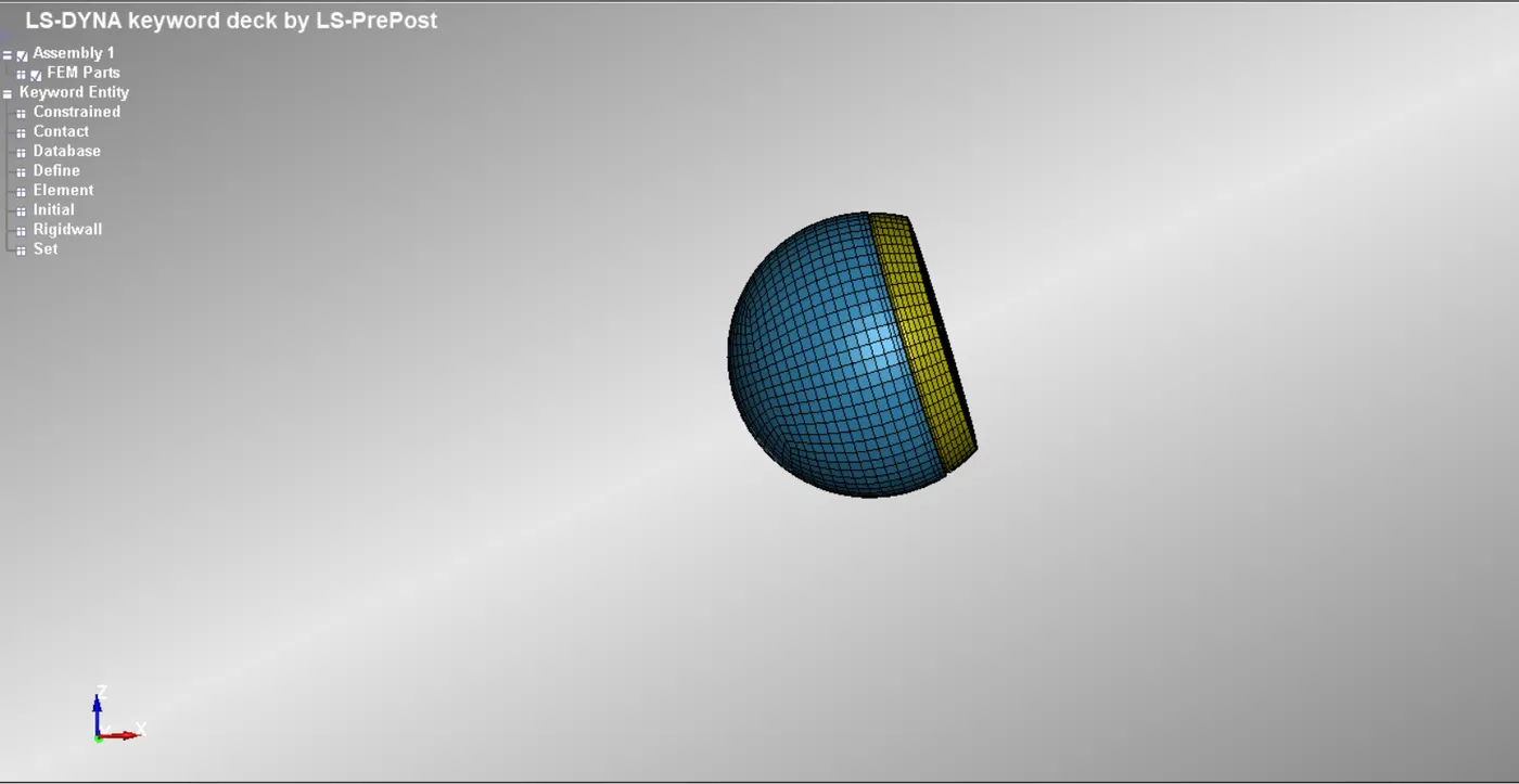
Fig 5 Pedestrian HeadFoam Model after transform
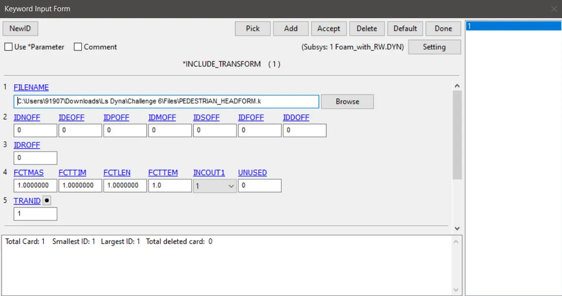
Fig 6 Include_Transform Card
Rest every cards are needed to same as we want the head foam model we want it to do the same what is done by the simple head.We then run it in program manager .We can have the look at the simulation in Ls prepost.
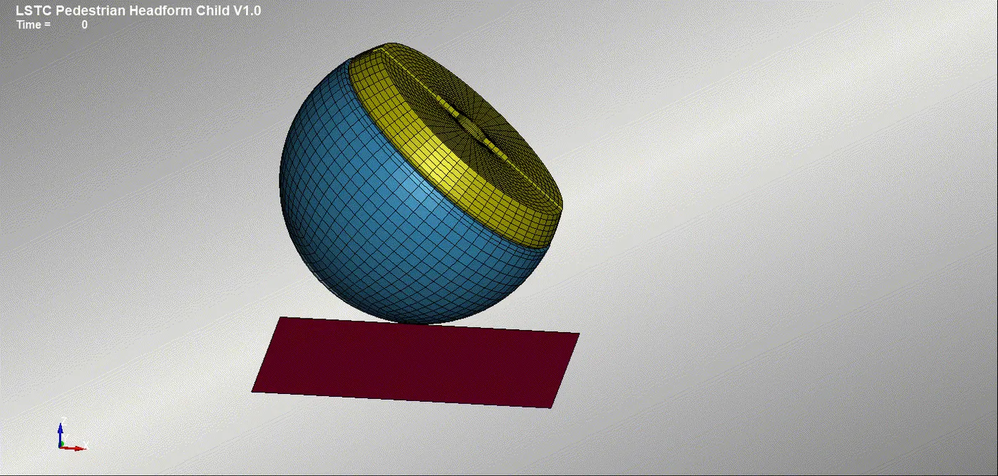
Fig 7 Impact of Head Foam Model on Rigid Wall
So we made sure that the simulation is doing the exact thing what we wants.So our utltimate aim is to have the simulation of the head foam model impacting with the hood.So we can replace the Rigid Wall with the Hood model we have.So we need to delete the Rigidwall and then using an include keyword we need to include the hood model.Also we need to have a contact_surface to Surface in which we need to create part set for head foam model and use it as the master and select the hood as the slave.
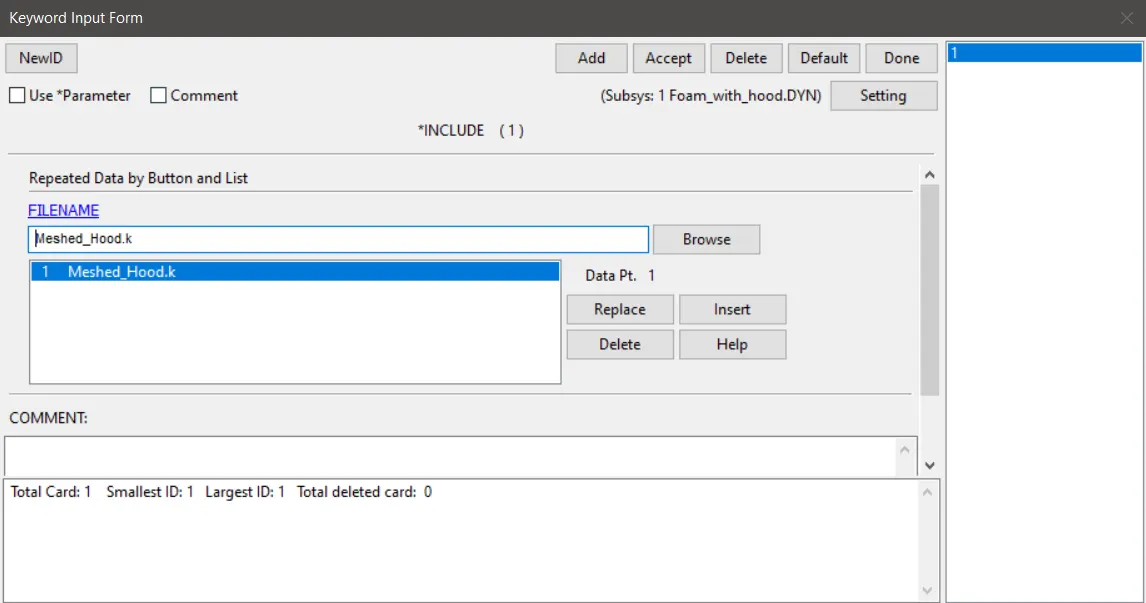
Fig 8 Include Card
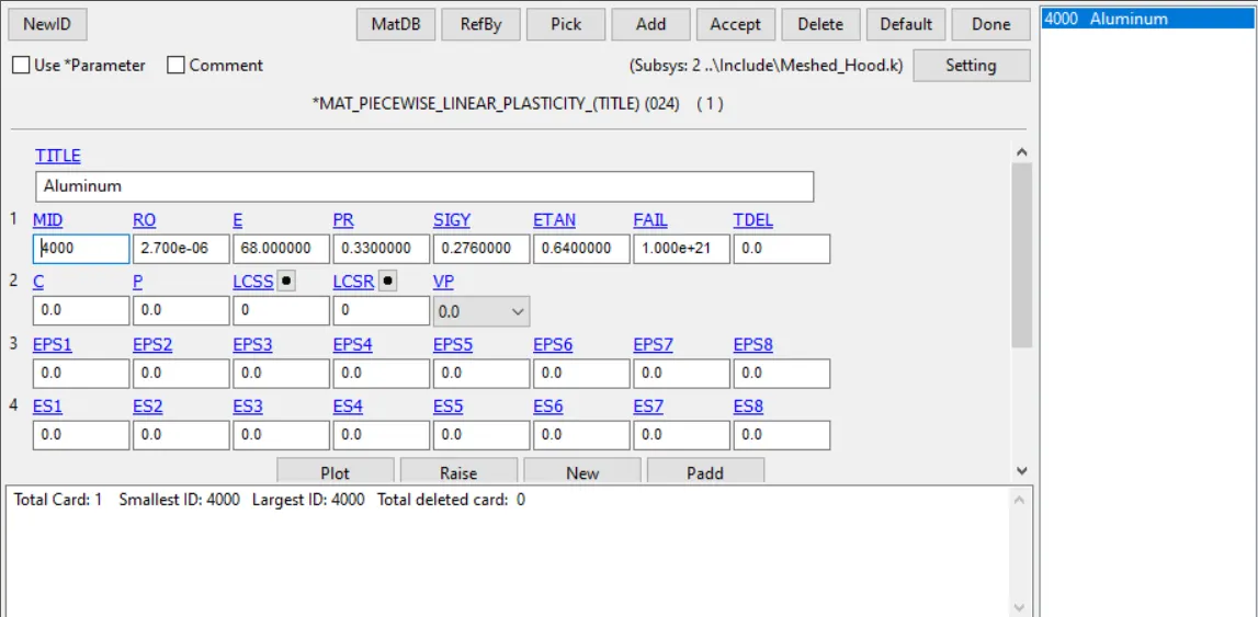
Fig 9 Material Card
The include keywords must be saved in the Main file subsystem as the main file must be proffessionally set up so that it must contain only the referance things ,Nothing else must not be there in the main file as this is expected to be a keyword file which contains only the referance made in the simulation.it must be referancing the other files.So that this file eill belooks proffesional an clean.
Then we can run the simulation.Then only we can find out the Head injury criteria of the particular simulation.From that we can infer that whether the hood model is sufficient for the pedestrian protection, or should we made any changes so that the pedestrian head will be protected even when a normal collision happens.
HIC is actually a number and a criteria based on that number at the same time.It is calculated based on a short lived acceleration but which is extremely time dependant which the head of the pedestrian suffers while making the impact.The collison itself makes the car to decclerate a lot as the driver brakes when he sees the collison is about to happen.At the same time the forces impart on the car dur to collison is high and destructive.Here we are discussing only the impact of the pedestrain head on the hood,But at the same time due to heavy and large decceleration happens due to braking the driver and occupants may move inside car rapidly and the head may strike with the steering wheel and may hit on the windshield or any parts of the car which will result in high impact forces and cause serious head injuries.These deadly injury making impacts also last only few fractions of second.
The Dummy foam head is having inbuilt sensors which records the acceleration of the head after the impact.So in real test we will be getting the Hic values using that accleration data.in simulation we need to calculate it using L s dyna itself.Since we can extract the accleration plot using the Nodout of ls dyna.HIC value also can be calculated using .
HIC value calculation invloves the calculation of average acceleration of the impact during a specific time interval.But this time interval is not necessarily be between the instant at which the crash happen and between the crash end time, it can be any time interval in between the crash begin and end time.So it basically means there will be an infinite time intervals in between.
But we need to have to be careful only about the time durations which are more than 3 ms and shorter than 36 ms. Because all the deccelerations happens above 36 ms will be not that injurious to the head foam ,this is what we experienced through so many impact tests.And also the peak acceleration should last for 3 ms.So we will be taking the time interval of 36 ms at which the peak acceleration happen.
Then we calculate the average acceleration at that time interval.With that average acceleration for that time interval we will be calculating this equation,
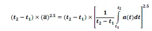
a^2.5 is the average acceleration and the factor a^2.5 (t1 - t2) is the HIC equation.HIC is calculated for that time period which have the peak acceleration more than 3 ms and the decceleration happens within 36 ms.
So 3 ms < (t1 - t2)< 36ms.
Note that the HIC number is not dimensionless. Rather, it is calculated in units of seconds ( g^2.5 where g itself is 9.8 m/s2).
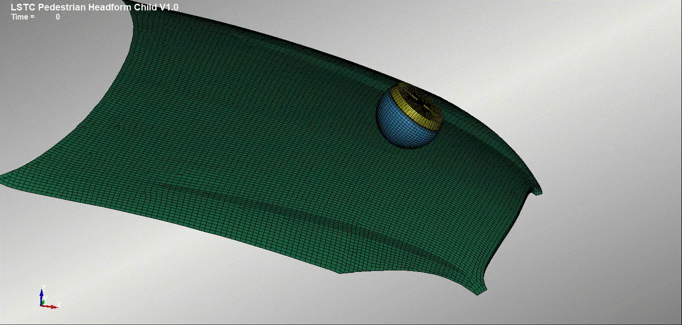
Fig 10 Head Foam Model Impacting On Hood Model
Results
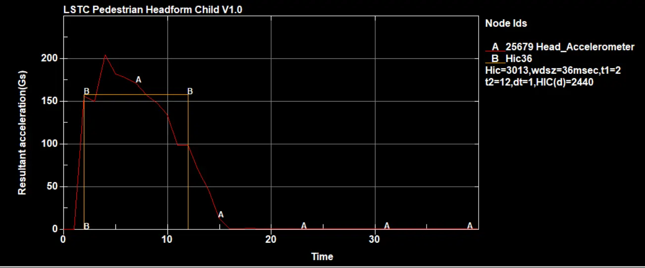
Fig 11 HIC Value with Thickness of hood as 4 mm
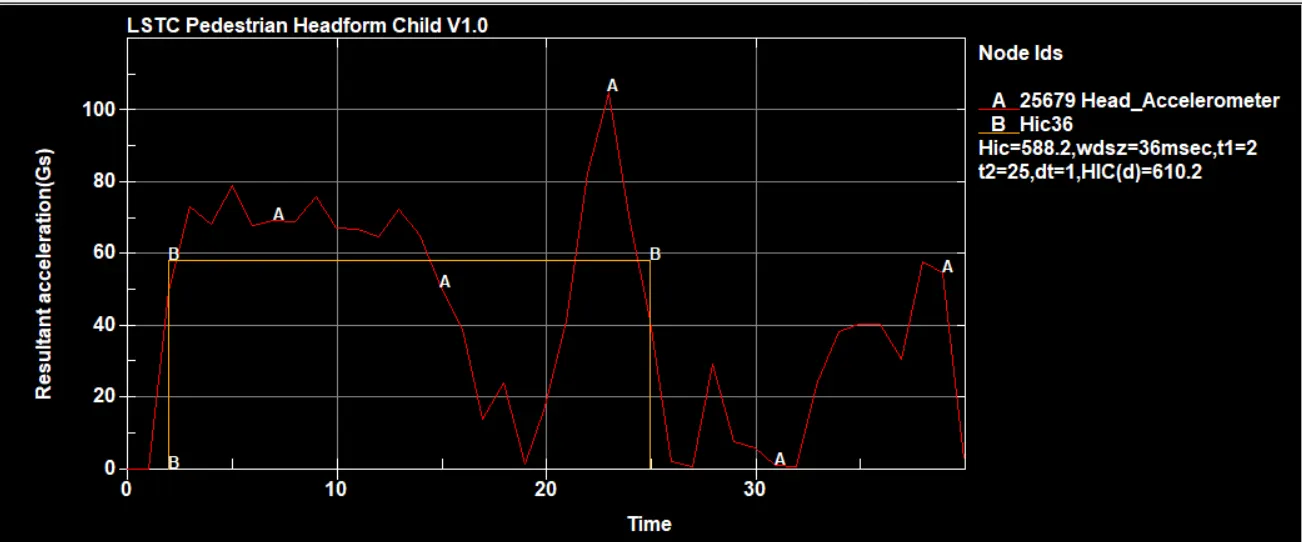
Fig 12 HIC value when Hood thickness is 3 mm
We can see the HIC value gets reduced as we reduce the thickness of the hood.The material structural strength is reduced as we reduce the thickness .So as the person head impacts on the less thickned surface the hood will suffers more deformation than the hood with more thickness , So obviously the pedestrian head will slows down in impact.We can clearly see that the resultant accelration is just 100 units in second case while in first case it is nearly 200.This values are the peak acceleration which results when the pedestrain head suffers maximum aecceleration.So we need to reduce the deccelration this is made possible by reducing the thickness of the hood.The HIC Value in first case is about 3013 which is very high value of HIC with this HIC the person may sufgfers the Level 5 injury risk which is concussion with or without skull fracture.So this hood is not suitable for the pedestrians .So basically with reducing the thickness as we cannot make the material chnage, we have the option to compromise little on thickness as we reduce the thickness to 3 mm which makes sure the hood componenet is structural strong at the same time it reduces the HIC value to just 588 .This is well below 600 HIC .This means the chnace of person escape from the injury risk due to impact is so high.
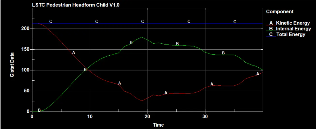
Fig 13 Energy Curves of the Pedestrain Impact Simulation
Energy curves also shows that the total energy is kept constant throughout the simulation and the head kinetic energy is getting converted into the internal energy of hood while it gets deformed.So the kinetic energy of the head reduces which mean it gets deccelerated and the HIC value also gets lowered if the decceleration time less than 3 ms.
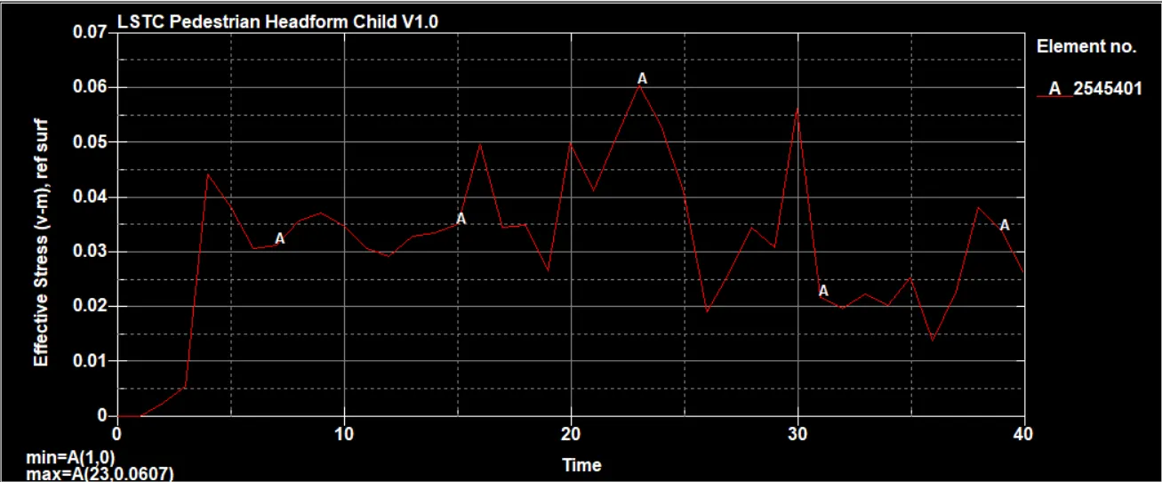
Fig 14 Stress plot with hood
We can see that maximum stress suffered by the hood is about 0.06 GPa .but the matrial card we given have the yield stres sof 0.276 GPa .So that suggest the model is within the elastic limit .So no plastic deformation happens to the hood.That is why the effective stress is given as zero throughout the runtime.
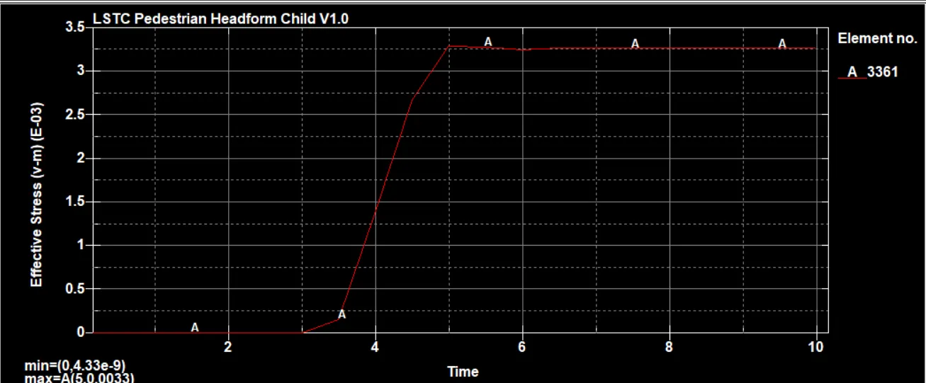
Fig 15 Stress in head foam element 3361 after impact
The stress shappens to the head foam is about 3.25 x 10^-3 GPa as the impacting surface is rigid.
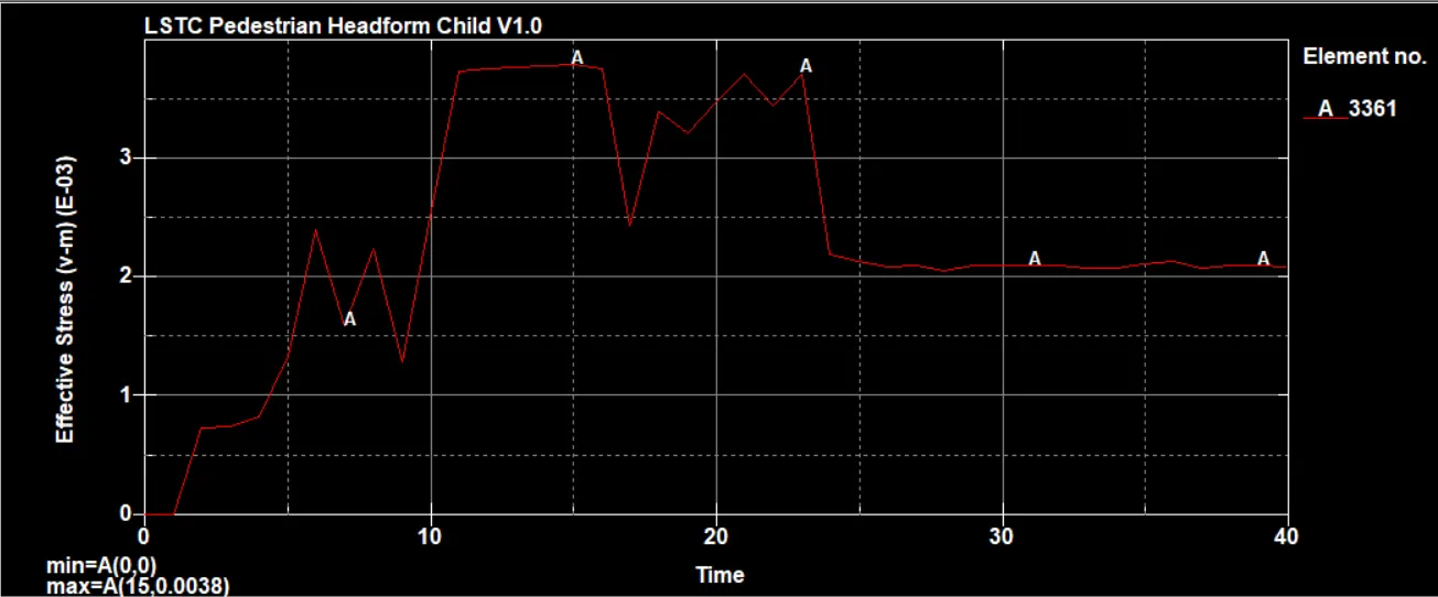
Fig 16 Effective stress on head foam element after impacting hood
Hood being a non rigid part the impact energy is taken some what by hood so the stress happens to the head foam is not like what we seen in case of rigid wall instead since the hood taken up some energy ,the stress will get reduced to 2.1 x 10^-3 GPa.
Conclusion
The pedestrain Impact causes innury to the pedestrains when the clearnace betweeen the hood and underlying stiff engine components are minimal.If we provide enough clearnace between the hood and undrlying componenet,then we can save the head of the pedestrian if we are using a optimized hood with lower HIC value in simulation preffferably less than 600. Hood will be optimized to make sure that the HIC value is less than 600 before using it in our vehicle.