Week-7 Head Impact
#8 // Week_ 7 Head Impact.
AIM: PEDESTRIAN HEAD IMPACT SIMULATION USING LS-DYNA.
OBJECTIVE:
To perform the Head Impact Simulation and calculate the Head Impact Criterion (HIC) value for the following cases.
- Simple head model impacting against a rigid wall.
- Child’s head-form dummy model impacting against a rigid wall.
- Child’s head-form dummy model impacting against the hood.
INTRODUCTION:
Pedestrian protection CAE is a part of vehicle safety engineering from a crash perspective. In pedestrian protection, we look for imparting minimum injury to the head, upper leg (thigh), and lower leg (including knee) in case of an accident with a human subject. These tests are usually done at a lower velocity from 20-40 kmph as accidents tend to result in more severe circumstances above these velocities and braking in case of an accident often results in collision at low velocities. The standard pedestrian test procedure by Euro NCAP is shown in Fig. 1.
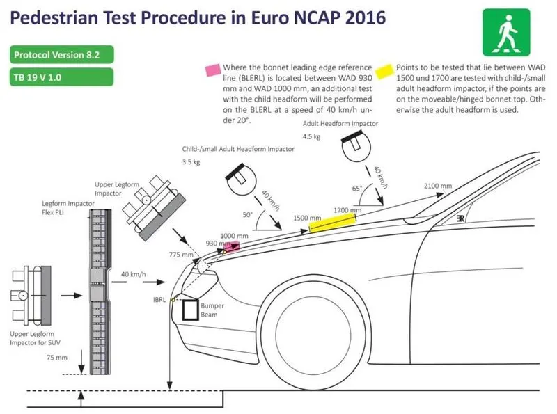
Fig.1. Pedestrian test procedure in Euro NCAP.
In this project, a children's headform model is provided. An impact simulation is created to replicate a scenario where this headform will impact a car bonnet. The bonnet is considered a rigid wall for the first and second cases, while for the third case, a meshed hood model is used with an elastoplastic material card. From the simulation, the head impact coefficient is calculated manually and with the help of LS-PrePost.
HIC, Head Injury Criterion/Coefficient is a quantification of head injury. A small HIC value doesn’t mean that the head injuries will be of low levels. Likewise, a high HIC doesn’t imply high-level injuries. The real meaning is that with higher HIC values, the higher the probability of getting high-level head injuries. The HIC is the maximum value over the critical time period t1 to t2 for the expression.
`HIC=max(t_1,t_2 ){[1/(t_2-t_1 ) ∫_(t_1)^(t_2) a(t)ⅆt]^(2.5) (t_2-t_1 )}`
HIC(d) = 0.75446 (Free Motion Headform HIC) + 166.4
At HIC=650,
90% probability of level one,
55% of level 2,
20% of level 3,
5% of level 4.
AIS-Abbreviated Injury Scale
- Slight damage to the brain with headache, dizziness, no loss of consciousness, and confusion.
- Concussion with or without skull fracture, less than 15 minutes of unconsciousness, detached retina, face, and nose fracture.
- Concussion with or without skull fracture more than 15 minutes of unconsciousness without severe neurological damage, multiple skull fractures, loss of vision, multiple facial fractures, or cervical fractures without damage to the spine.
- Multiple skull fractures with severe neurological damage.
Note: The unit system used is kg-mm-ms.
PROCEDURE:
Case (1): Simple head model impacting against rigid wall:
The given LS-Dyna keyword file of the simple head FE model is opened in LS-Pre-Post using the option File > Open > LS-Dyna Keyword File.
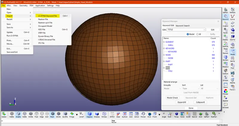
1. Part definition ->
Section properties:
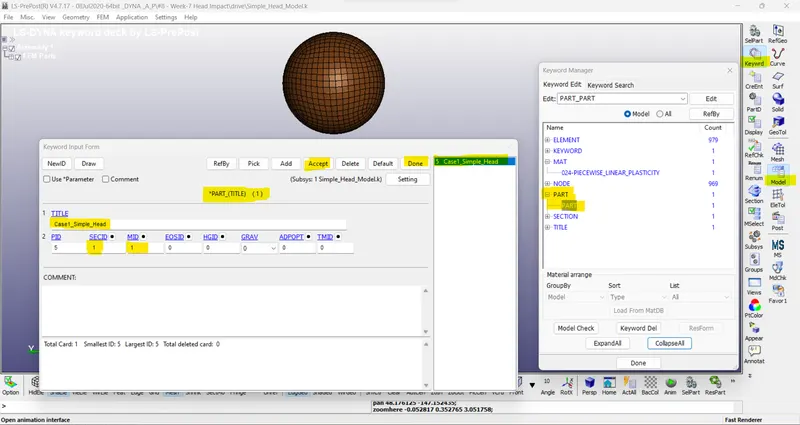
The section properties of the simple head are assigned as shell element with 2.5 mm thickness and ELFORM=2, Belytschko-Tsay element formulation.
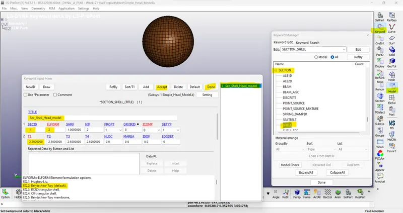
Material properties:
MAT24 (Piecewise linear plasticity) material card is used to assign the steel material properties to the simple head model. The MAT24 represents Piecewise linear isotropic plasticity. With this material model, it is possible to consider the effect of the strain rate.
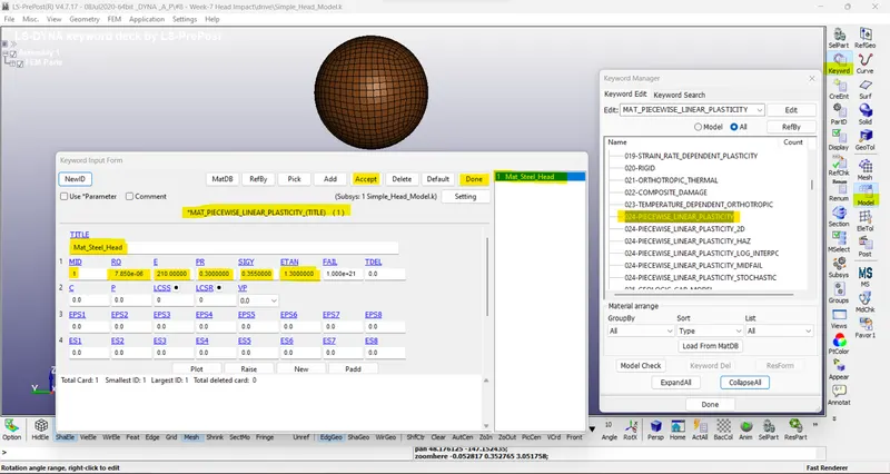
Now, assign Sections & Material IDs in PART.
2. Boundary condition ->
Initial velocity:
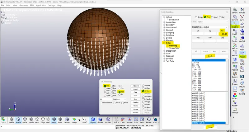
The simple head model is assumed to be impacting the rigid wall at a velocity of 40kmph i.e., 11.11 mm/ms in a negative Z-direction towards the rigid wall.
Rigid wall planar:
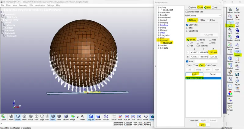
The rigid wall is created at a distance of 15 mm from the bottom of the simple head model.
Contact details:
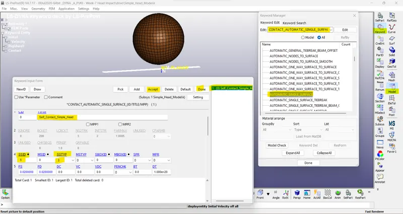
The contact type selected is AUTOMATIC_SINGLE_SURFACE. It is quite helpful to apply this contact method in the crash models because all the elements are included in one single set and LS-DYNA considers also when a part comes into contact with itself. The FS and FD are static and dynamic friction coefficients with a value of 0.02 entered in the contact card. The simple headform model is the slave (SSID=5).
3. Control and Database options:
Control function:
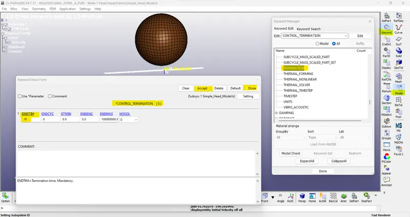
The control termination function is enabled to specify the end time of the simulation. The termination time is set for 10 ms.
Database options:
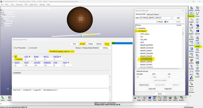
The time step value of 0.5 ms is given for the BINARY_D3PLOT and DATABASE_ASCII options for GLSAT, NODOUT, and RWFORC.
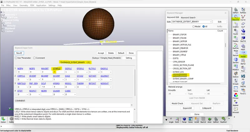
DATABASE_EXTENT_BINARY card with STRFLG =1, is used to compute the elastic strain in the model.
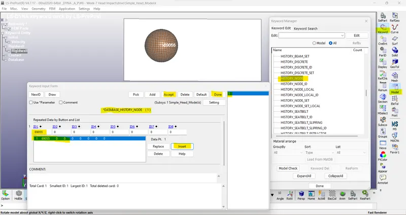
DATABASE_HISTORY_NODE card is used to compute the HIC value of a 69055 node in the model.
The keyword file created is checked for errors using the option keyword manager > model check. The keyword file is saved using ‘.k’ extension and is made to run in the solver by getting a normal termination message.
Case (2): Child headform dummy model impacting against the rigid wall:
1. Part definition-
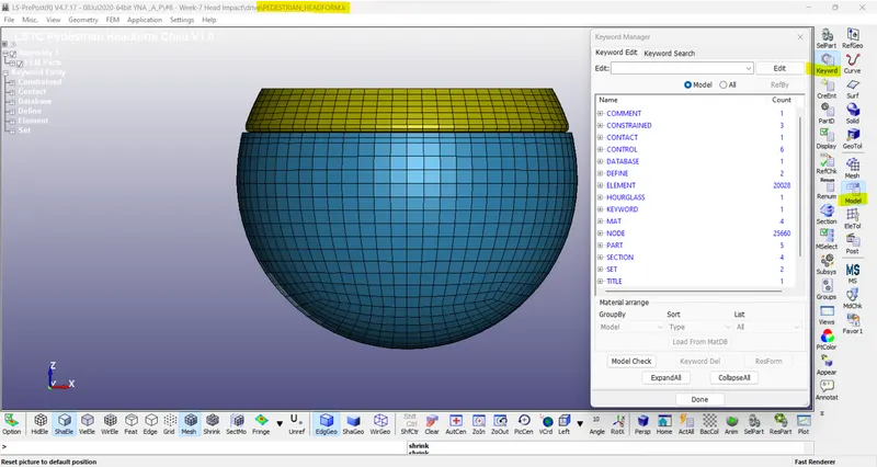
The standard dummy model of the child headform was provided with the necessary keyword for impact simulation as shown in default (PEDSETRIAN_HEADFORM.k // default Sub-System include file).
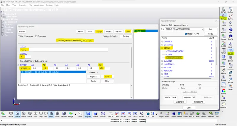
For case (2) impact simulation, the provide standard dummy model of child headform has to be rotated about 450 along Y-axis to replicate the Euro NCAP impact simulation as shown above (default Sub-System include file), by pulling it into a new keyword file created by LS-PrePost by using *DEFINE_TRASFORMATION and *INCLUDE_TRANSFORM as shown in the below.
// Using DEFINE_TRANSFORMATION card with TRANID=1, the dummy headform model is rotated by OPTION > ROTATE along Y-axis (A2=1) by 450 (A7=45).
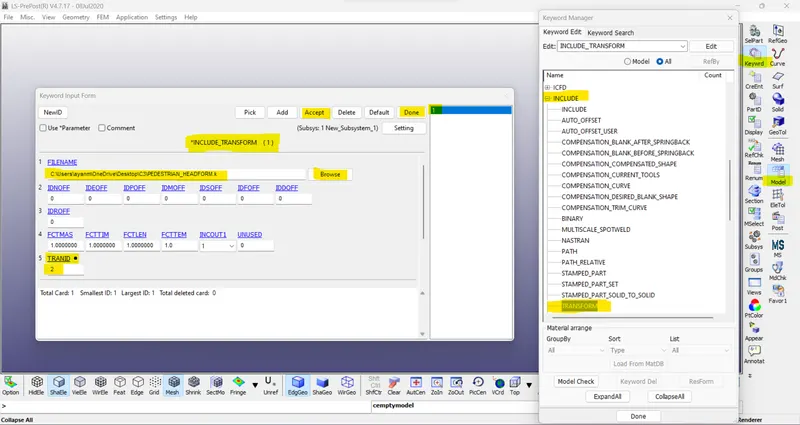
// INCLUDE_TRANSFORM card is used to pull the rotated standard dummy headform model file to the main file. The main file is saved with ‘.k’ extension.
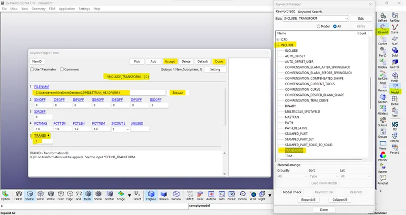
- /// Note: Filenames and pathnames are limited to 236 characters spread over up to three 80-character lines.
- /// After this operation save this file & Exit from LS_Pre-post > Then Open a new LS_Pre-post & import this newly form keyword. (Case2.k)
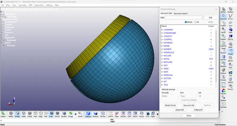
The main file is opened in LS-PrePost as shown below, to add the necessary keywords to complete the simulation setup.
//Note: While adding keywords to the main file, ensure the Subsys: is set to the main file .k extension.
2. Boundary condition ->
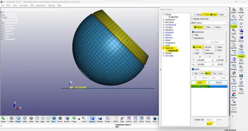
Rigid wall planar:
The rigid wall is created at a distance of 15 mm from the bottom of the standard dummy headform model.
//Note- Use Translet / Rotation for appropriate Normal.
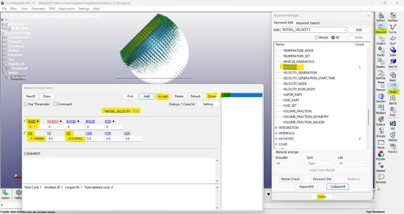
Initial velocity:
As per Euro NCAP standards, the initial velocity is taken as 40 kmph i.e., 11.11 mm/ms at an angle 450. The vertical and horizontal components of the velocities are -7.14 mm/ms (VX) and -8.51 mm/ms (VZ) respectively.
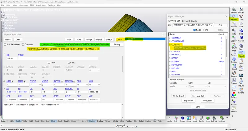
Define Contacts:
/ Default CONTACT_AUTOMATIC_SURFACE_TO_SURFACE card is provided in the subsystem file.
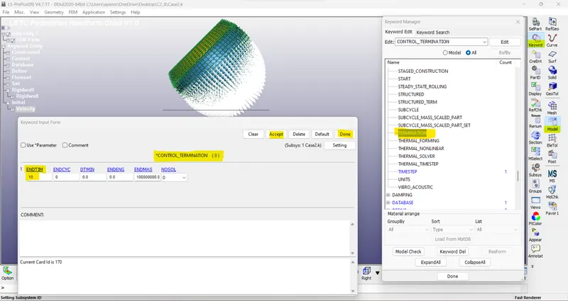
3. Control and Database options:
Control function:
The termination time is set for 10 ms.
Database options:
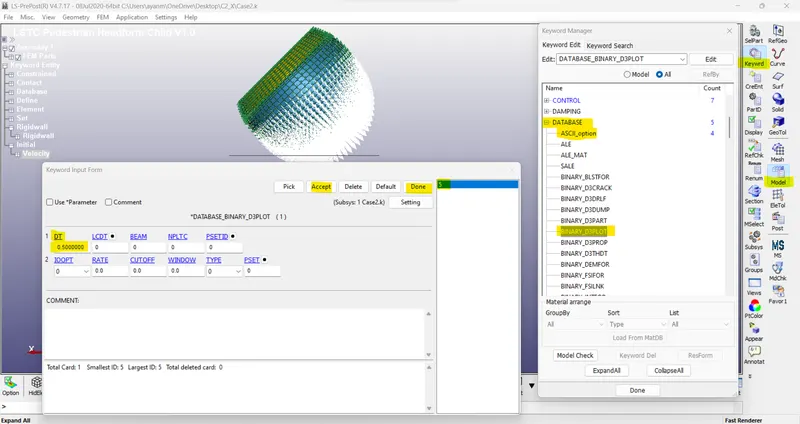
The time step value for the BINARY_D3PLOT and DATABASE_ASCII options for GLSAT, NODOUT, and RWFORC is given as 0.5 ms.
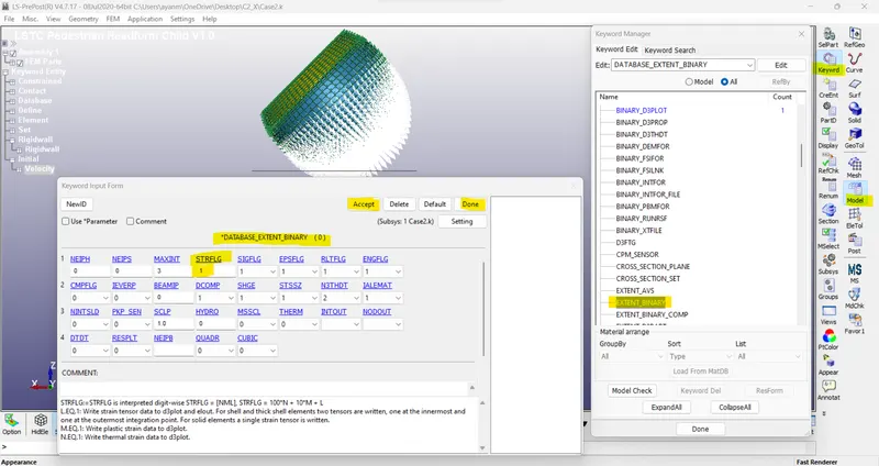
DATABASE_EXTENT_BINARY card with STRFLG =1, is used to compute the elastic strain in the model.
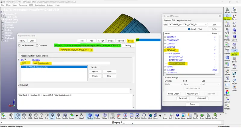
DATABASE_HISTORY_NODE card is used to compute the HIC value of a 25679 node in the model.
/ Default DATABASE_HISTORY_NODE_ID_25679 inserted in subsystem file. so, no need to add another one.
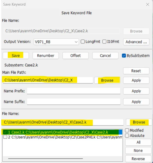
// Save the main file in “.k” ->
The keyword file created is checked for errors using the option keyword manager > model check. The keyword file is saved to the main file using the ‘save keyword as’ option as shown below the main file is made to run in the solver by getting a normal termination message.
Case (3): Child headform dummy model impacting against hood:
In case_3 first, we have to provide the Scetion_Shell card, Material card & Part define for the meshed hood in the “Meshed_Hood.k” subsystem file & save it.
1. Section properties ->
The section properties of the hood are assigned as shell element with 1.5 mm thickness and ELFORM=16, Fully integrated shell element (very fast).
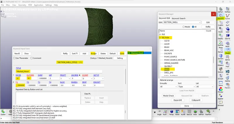
2. Material properties ->
MAT24 (Piecewise linear plasticity) material card is used to assign the Aluminium material properties to the hood. The MAT24 represents Piecewise linear isotropic plasticity. With this material model, it is possible to consider the effect of the strain rate.
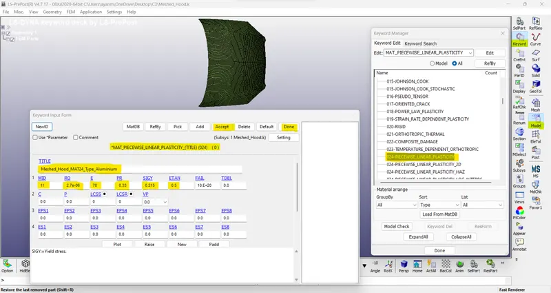
3. Part definition ->
/ Now, assign the SECID & MID in PART. Then saving that 'Meshed_Hood.k' subsystem file.
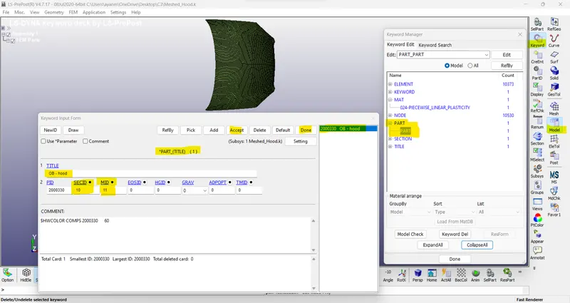
//
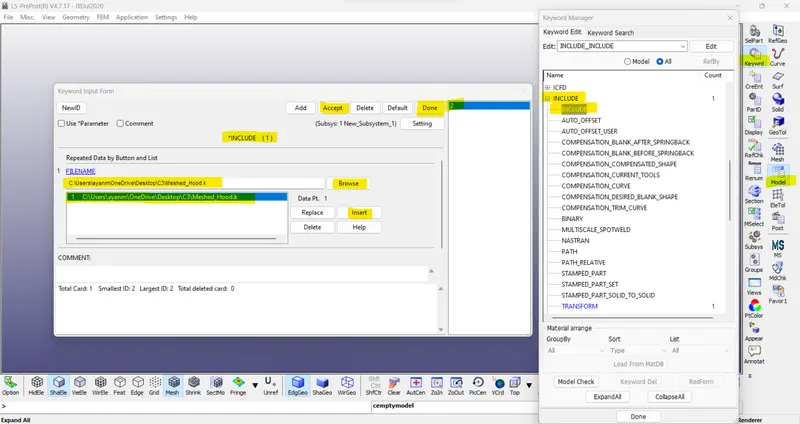
The keyword file of the hood is saved using ‘.k’ extension. The keyword file of the hood is pulled into the main file using keywords *INCLUDE as shown below. The child headform is pulled into the main file by using keywords -*DEFINE_TRASFORMATION and *INCLUDE_TRANSFORM which is similar to the case (2) scenario.
/ Case2 > include PEDESTRAIN_HEADFORM.k subsystem file to main file ->
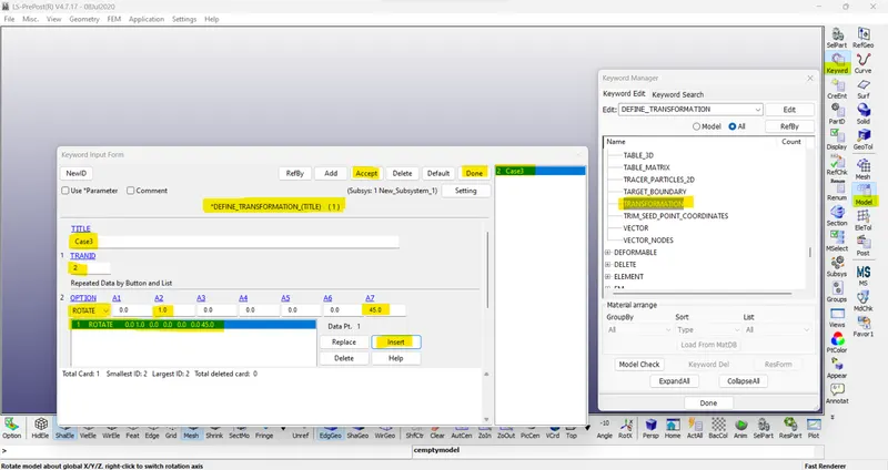
/ Case3 > include Meshed_Hood.k subsystem file to main file ->
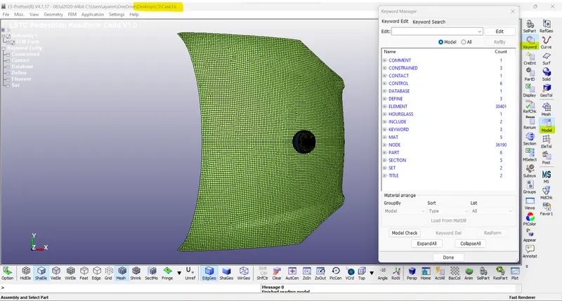
// The main keyword file is opened in LS-PrePost as shown below to add the necessary keywords to complete the impact simulation setup (main file).
1. Boundary condition ->
Initial velocity:
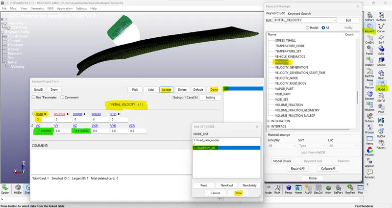
As per Euro NCAP standards, the initial velocity is taken as 40 kmph i.e., 11.11 mm/ms at an angle 450. The vertical and horizontal components of the velocities are -7.14 mm/ms (VX) and -8.51 mm/ms (VZ) respectively.
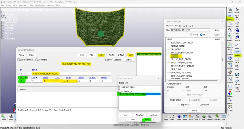
2. Boundary SPC:
Using create entity option the nodes on the outer edges of the hood are selected and constrained all the translational & rotational motion using the option boundary SPC set.
/ Note- Create a node set for boundary nodes of Meshed hood.
3. Contact details:
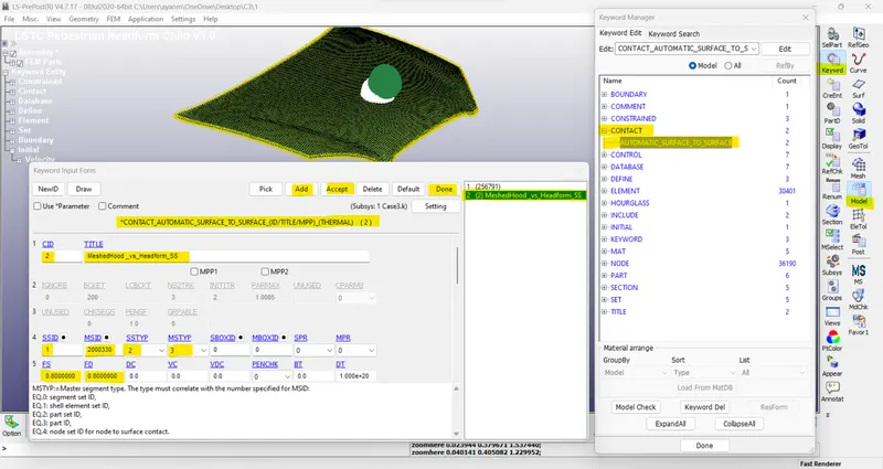
CONTACT_AUTOMATIC_SURFACE_TO_SURFACE card is used to define contact between the hood and dummy child headform model. The child headform model is taken as slave and hood as master. The FS and FD are static and dynamic friction coefficient with a value of 0.8 is entered in the contact card.
/ Note: Increasing the value of FS and FD also increases the value of HIC, hence choose the appropriate value for FS and FD.
4. Control and Database options:
The control card and database cards are the same as that of the case (2) scenario.
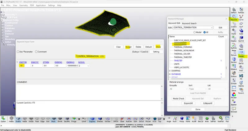
Control function:
The termination time is set for 10 ms.
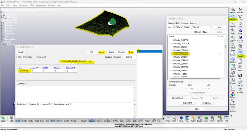
Database options:
The time step value for the BINARY_D3PLOT and DATABASE_ASCII options for GLSAT, NODOUT, and RWFORC is given as 0.5 ms.
DATABASE_EXTENT_BINARY card with STRFLG =1, is used to compute the elastic strain in the model.
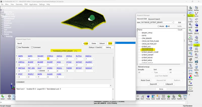
/ DATABASE_HISTORY_NODE card is used to compute the HIC value of a 25679 node in the model.
/ Default DATABASE_HISTORY_NODE_ID_25679 inserted in subsystem file. so, no need to add another one.
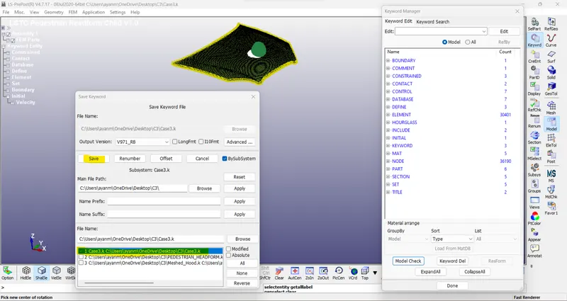
The keyword file created is checked for errors using the option keyword manager > model check. The keyword file is saved to the main file using the ‘save keyword as’ option as shown below. The main file is made to run in the solver by getting a normal termination message.
RESULTS:
The D3plot output file is opened in LS-PrePost using the option File>open>LS-Dyna binary plot.
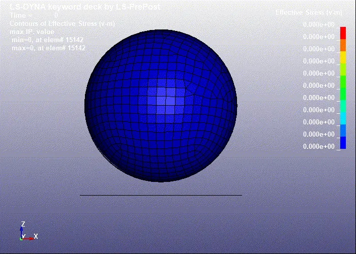
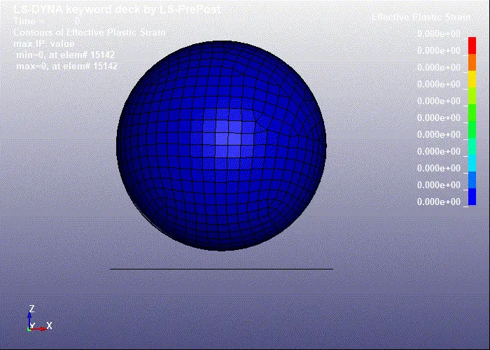
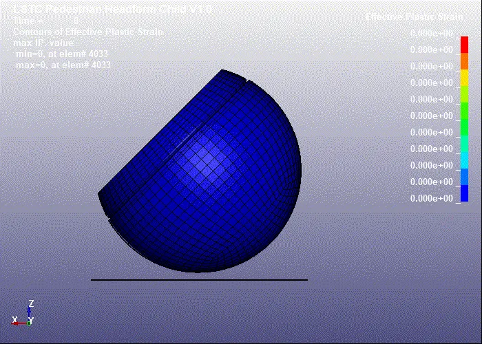
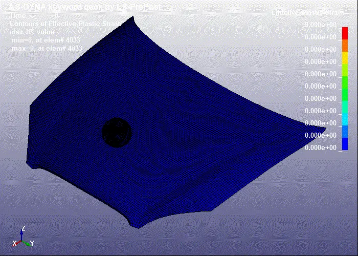
- The animation of Von-Mises stress and Effective plastic strain contour is shown below.
/ v-m stress contour for case_1 ->
/ Effective plastic strain contour for case_1 ->
/ v-m stress contour for case_2 ->
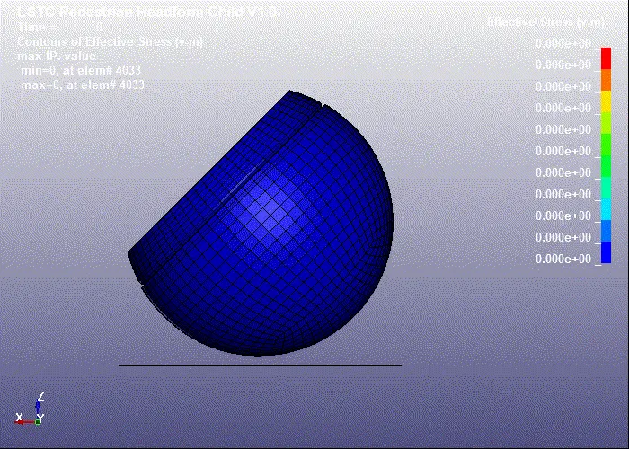
/ Effective plastic strain contour for case_2 ->
/ v-m stress contour for case_3 ->
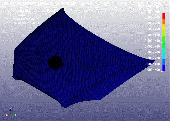
/ Effective plastic strain contour for case_3 ->
2. Stress / Strain plots ->
/1/ Simple_Head_Impacting_Rigidwall. ->
/ v-m stress plot for an element_case-1
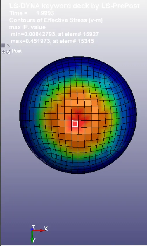
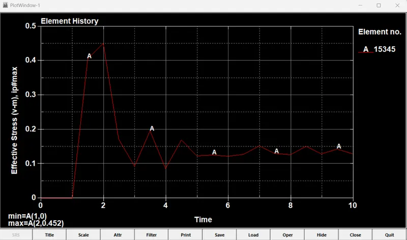
> In the first case, during the instant of impact, the maximum v-m stress developed is 4.520e-01 GPa in the element 15345 at 2 ms which is beyond the yield stress value of 0.355 GPa.
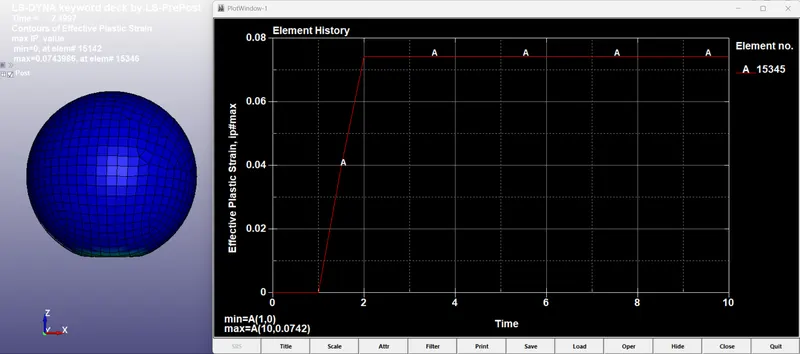
/ Effective Plastic Strain plot for an element_case-1
> Max Strain 0.0742 at 2 ms (constant up to 10ms) in element 15345.
/2/ Pedestrian_Headform_Impacting_Rigidwall. ->
/ v-m stress plot for an element_case-2
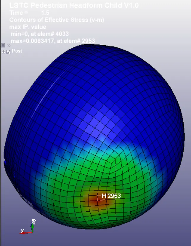
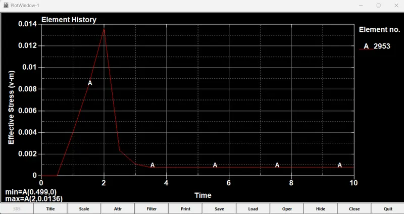
> In the second case, during the instant of impact, the maximum v-m stress developed is 8.342e-03 GPa in the element 2953 and reaches a peak value of 1.36e-02 GPa at 2 ms and later the value of v-m stress reduces due to the bouncing back of the headform from the rigid wall.
/ Effective Plastic Strain plot for an element_case-2
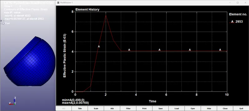
> Max Strain 7.69e-03 at 2 ms in element 2953.
/3/ Pedestrian_Headform_Impacting_Meshed_Hood. ->
- // Pedestrian_Headform Stress/Strain plots -
/ v-m stress plot for an element_case-3
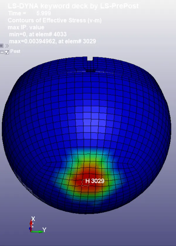
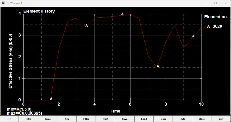
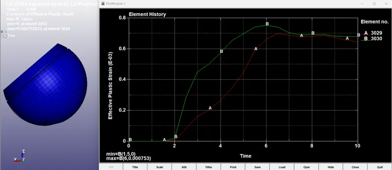
> In the third case, during the instant of impact the maximum v-m stress developed is 3.950e-03 GPa in the element 3029 at 6 ms and later it fluctuates steadily until the headform bounces back from the hood.
/ Effective Plastic Strain plot for an element_case-3
> Max Strain 0.753e-03 at 6 ms in element 3030.
- // Meshed_Hood Stress/Strain plots -
/ v-m stress plot for an element_case-3
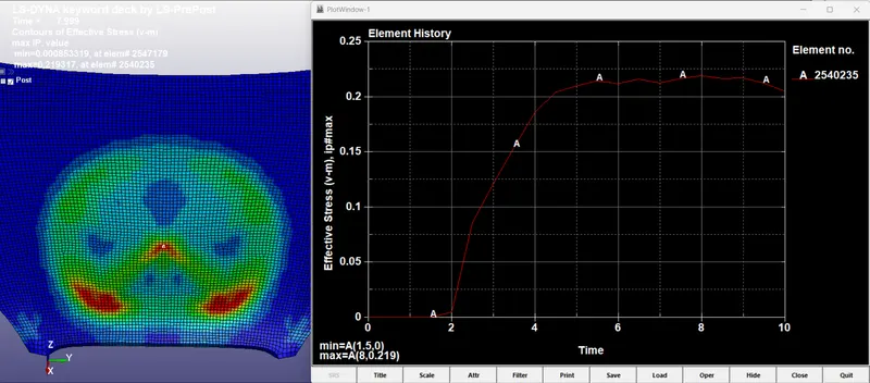
> Max Stress 0.219 Gpa at 8 ms in element 2540235.
/ Effective Plastic Strain plot for an element_case-3
> Max Strain 0.0117 at 10 ms in element 2540235.
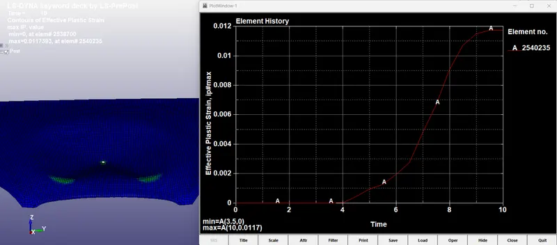
The v-m stress induced in the element for the third case is less compared to the second case because the hood gets deformed due to the impact and absorbs the energy, unlike the rigid wall which does not get deformed during impact.
3. Resultant Acceleration polt ->
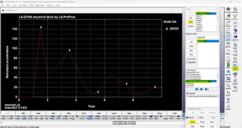
/1/ Simple_Head_Impacting_Rigidwall. / CASE_1->
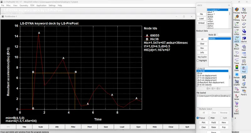
/ Max Acceleration 142 mm/ms2 at 1.5 ms.
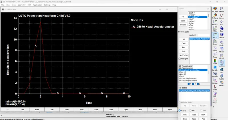
/2/ Pedestrian_Headform_Impacting_Rigidwall. / CASE_2 ->
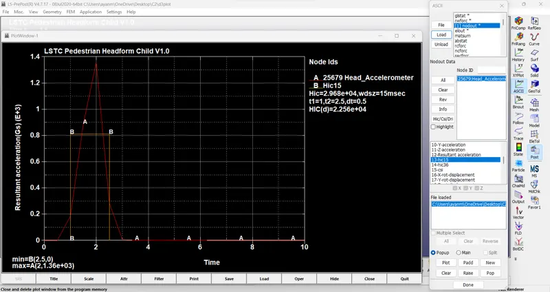
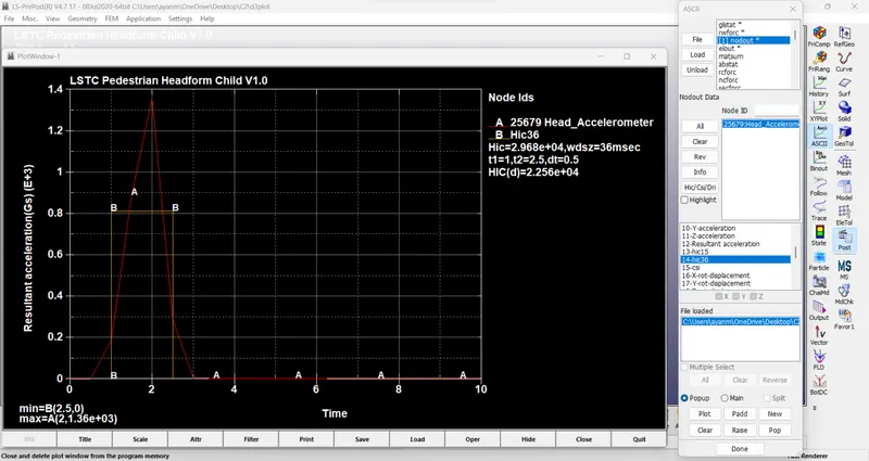
/ Max Acceleration 13.4 mm/ms2 at 2 ms.
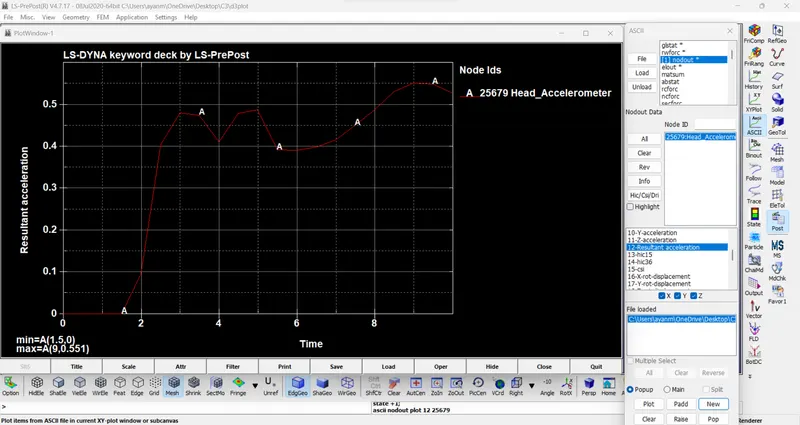
/3/ Pedestrian_Headform_Impacting_Meshed_Hood. / CASE_3 ->
/ Max Acceleration 0.551 mm/ms2 at 9 ms.
4. Head Injury Criteria (HIC15 /HIC36) ->
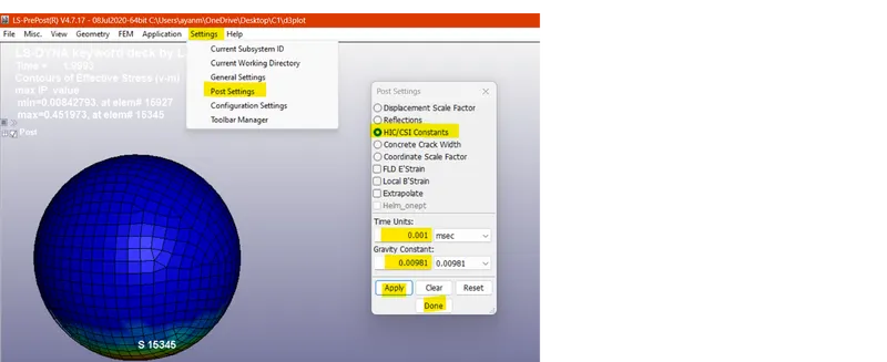
/Note- First, Set the HIC unit system as per the set-up unit system in '.k'
/ Go to LS-Dyna option panel>Settings>Post Settings>HIC/CSI Constrants>Set Time Units / Gravity Constant./
/1/ The resultant acceleration plot with HIC15 /HIC36 value for case (1)
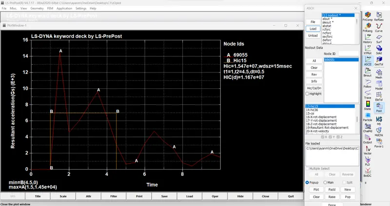
/2/ The resultant acceleration plot with HIC15 /HIC36 value for case (2)
/3/ The resultant acceleration plot with HIC15 /HIC36 value for case (3)
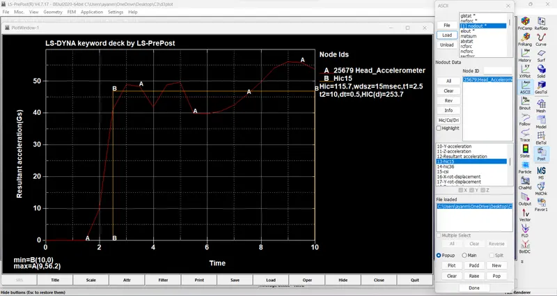
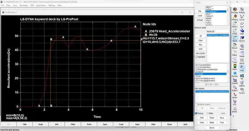
From the plot, the HIC15 value for the first and second cases is beyond the safe value because the head model is impacting the non-deformable rigid wall. The HIC15 value obtained from LS-PrePost for the third case is 115.7 and HIC(d) value is 253.7 which is less than the safe HIC value of 650 as per Euro NCAP Protocol because the hood absorbs the impact energy and gets deformed.
Manual calculation of HIC value:
The expression to calculate the HIC value is,
HIC = `(max)┬(t_1,t_2 ) {[1/(t_2-t_1 ) ∫_(t_1)^(t_2)a(t)dt]^2.5 (t_2-t_1 )}`
From the plot,
The average value of acceleration for the time interval of t1=2.5 ms and t2=10 ms is,
`[1/(t_2-t_1 ) ∫_(t_1)^(t_2)a(t)dt]`
Therefore,
`t_2-t_1 = 7.5ms = 7.5 / 1000 s = 0.0075s`
`HIC = [(1/7.5) times 46.9 times7.5] ^2.5 times(7.5/1000)`
= 112.977, which is nearly equal to the value that we got from the solver.
Now,
`HIC(d)`=0.75446(Free Motion Headform HIC) +166.4=0.75446×112.977+166.4= 251.6366. (FMVSS 201U says that HIC(d) has to be limited to 1000.)
The HIC15 value obtained from LS-PrePost for the third case is 115.7 and HIC(d) value is 253.7. The HIC15 value obtained from the manual calculation for the third case is 112.977 and HIC(d) value is 251.6366. There is a small variation in the HIC value obtained from LS-PrePost and manual calculation which is acceptable.
Post Analysis-
as we know that in 1st case, we had taken only the outer shell which is made of steel whose mechanical properties such as young modulus, and yield stress are much higher than the actual head so we experienced maximum stress in cases 1 and maximum strain. there is minimal deformation in the simple head geometry. That’s why the HIC values are too high.
in case 2 we had used child head foam which is a reorientation of the actual head with related material but we had used a rigid wall for impact, so we had used plastic linear plastic material also. the rigid wall is unreformable so the total stress is transferred to the head and deforms the head foam geometry severely the HIC values are lower than case 1.
in case 3 we used actual head foam as in case 2 and we used an actual hood model with aluminum material as in real-life uses, as we had used thin aluminum material with linear piecewise material which is easily deformable in case of an accident. thus, we experienced the lowest strain which is also negligible, and the HIC value is also very less which is 115.7 only.
CONCLUSION:
- The impact simulation of pedestrian head form is created for a simple case scenario to a complex real-time scenario i.e.,
case_1: Simple head model impacting against a rigid wall.
case_2: Pedestrian headform model impacting against a rigid wall.
case_3: Pedestrian headform model impacting against the hood.
- The computational time required for simple cases is less compared to real-time case scenarios but the accuracy of the results is poor for simple cases.
- There is a variation in the values for stress/strain and HIC15 for all the cases because of the difference in material properties and boundary conditions.
- The HIC15 value obtained for case 3 was within the standard safe HIC15 value of the EURO NCAP protocol.