Week-7 Head Impact
AIM:
To perform the Head Impact Simulation and calculate the Head Impact Criterion (HIC) value for the following cases.
- Simple head model impacting against rigid wall
- Child headform dummy model impacting against rigid wall
- Child headform dummy model impacting against hood
Objective:
In this challenge, a children's head foam model is provided and supposed to replicate a scenario where this head foam will impact a car bonnet. The hood model is an elasto-plastic material card that has to be used. From the simulation, the head impact coefficient must be calculated manually and with the help of LS-PrePost. There are three cases that are simulated and compared to each other.
Case1: Simple head model and rigid wall.
Case2: Child head-foam and rigid wall.
Case3: Child head-foam and Hood.
INTRODUCTION:
Pedestrian head impact:
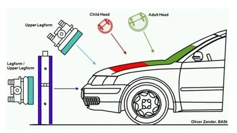
Pedestrian protection CAE is a part of vehicle safety engineering from a crash perspective. In pedestrian protection, we look for imparting min injury to head,upper leg (thigh), and lower leg (including knee) in case of an accident with a human subject.These tests are usually done at a lower velocity from 20-40 kmph as accidents tend to result in more severe circumstances above these velocities and braking in case of an accident often results in collision at low velocities.
Many pedestrian crashes involve a forward moving car (as opposed to cars and other vehicles with a vertical hood/bonnet).
In such a crash, a standing or walking pedestrian is struck and accelerated to the speed of the car and then continues forward as the car brakes to a halt. The pedestrian is impacted twice, first by the car and then by the ground, but most of the fatal injuries occur due to interaction with the car.
Vehicle designers usually focus on understanding the car-pedestrian interaction, which is characterized by the following sequence of events: the vehicle bumper first contacts the lower limbs of the pedestrian, the leading edge of the hood hits the upper thigh, and the head and upper torso are struck by the top surface of the hood and/or windshield.
HIC:
Crash safety engineers consider the head which is more prone to injury that could lead to concussions or even death to be their main priority during crash analysis.
The factor that is used by engineers to determine the level of damage imparted onto the head region is determined using the HIC factor which stands for Head Injury Criterion / Coefficient.
Normally the variable is derived from the measurements of an accelerometer mounted at the centre of a crash dummy's head, when the dummy is exposed to crash forces.
Generally, it is defined by
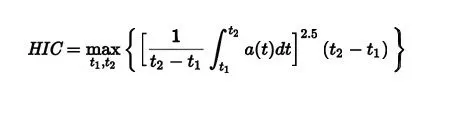
where t1 and t2 are the initial and final time period chosen to maximize HIC and a is the accelaration over the period of time from t1 to t2.
Procedure:
CASE 1: The impact simulation of a simple head impact with the Rigid wall.
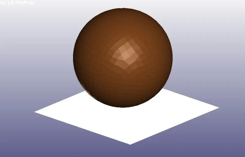
1.The first case is setting up the head model and creating a rigid wall and get the HIC values. So, starting with the model set up, the simple_head.k file is imported.
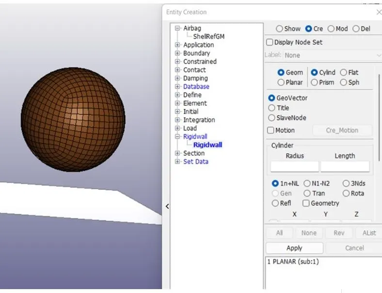
Rigidwall creation:
SECTION KEYWORD:
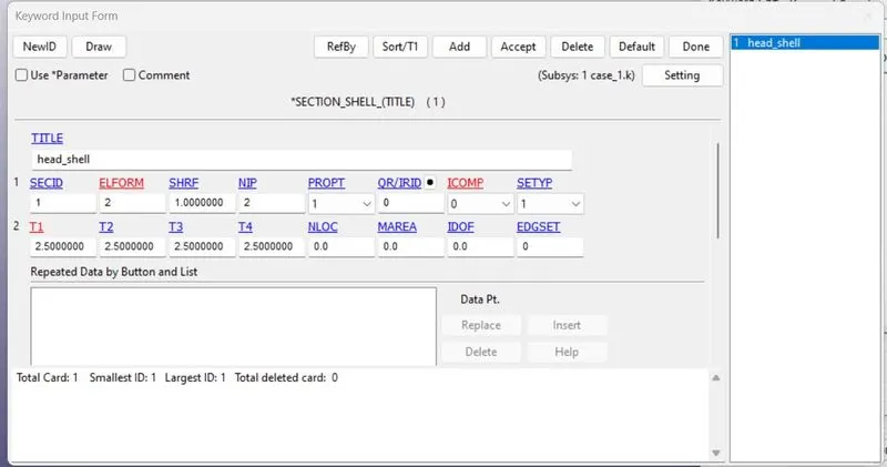
Section card is used to define the element type and thickness. T1 is the thickness which is defined as 2.5 mm and the ELFORM 2 is chosen.
MAT_Elastic :
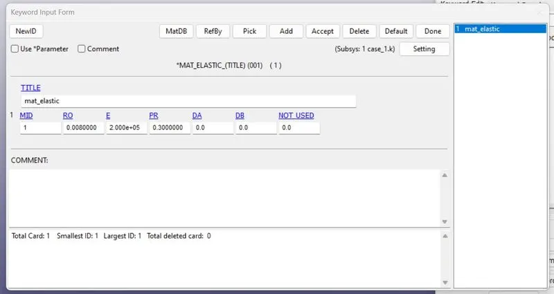
This keyword is used to define the material to the model. Here simple elastic material is considered for the first case.
NODE_SET:
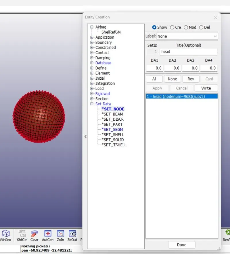
This keyword is used to create a set of selected elements. Since we need our velocity to be applied to all the nodes present on the model, so the nodes-by part were selected. Create entities-Node set Id-Create.
INITIAL_VELOCITY:
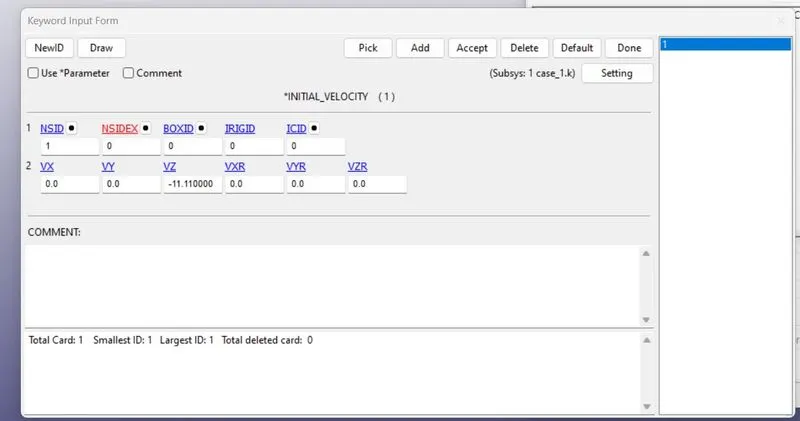
This keyword is used to define the velocity to the model. NSID is selected add the id we created in previous step. The velocity is given in z direction.
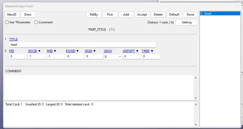
PART DEFINITION:
Part is defined with the SECID and MID.
CONTROL KEYWORD:
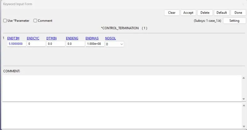
This keyword is used to provide the control over the simulation. Termination keyword the card used to define the termination time of the simulation.
CONTACT KEYWORD:
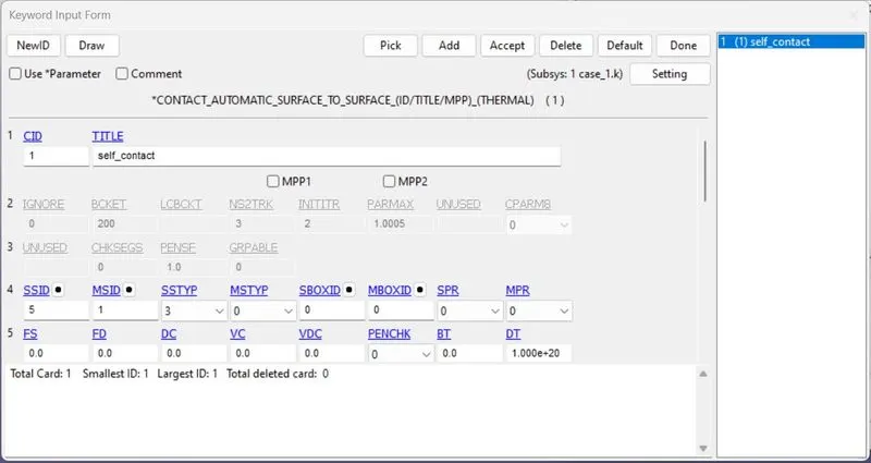
Contact keyword is used to define the contact between the two models. Here, single we have one model as head and another as a rigid wall, so automatic_single_contact is used and only head is defined as slave since the rigid is master.
DATABASE KEYWORD (OUTPUT FILES):
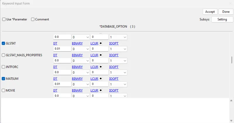
ASCII:
This contains all the output request keywords for a number of energies.
GLSTAT:- Global statistics, used to get energies.
NODOUT:- Used to get nodal data.
MATSUM:- Used to get material energies.
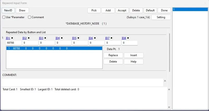
HISTORY_NODE:
This keyword is used to define the node history.
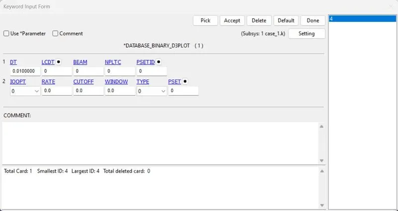
Binary D3PLOT:
This keyword is used to define the time intervals between the output requests.
Solve the problem with LS run.
Results:
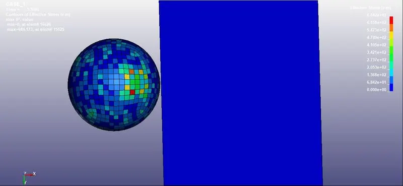
Von mises stresses are given as,
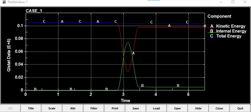
Energy plot for the same in the form of internal,kinetic and total energy is as bellow,
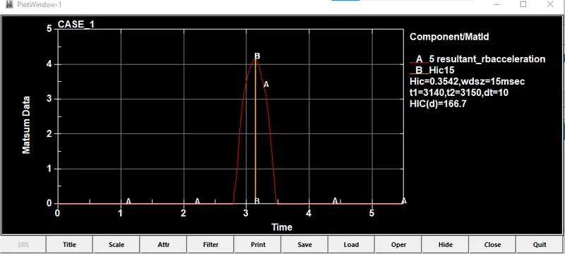
HIC value for the simple model is 168.
CASE(II)
The impact simulation of the Head-form with the Rigid wall.
A head form model is imported using include transform keyword and rotated by 45 degree at y axis and the model is set up for the simulation.
1.Consider a headfoam model as given.
2.Open new empty model in LS Dyna and use keyword Define-Transformation.
3. In the above keyword use rotate command and use appropriate X,Y,Z direction cosines and enter 45 deg as rotation angle.
4.Now use include transform keyword to affect the transformation on desired file.
5.Save as the new file to main_pedestrian_head file and reopen it.
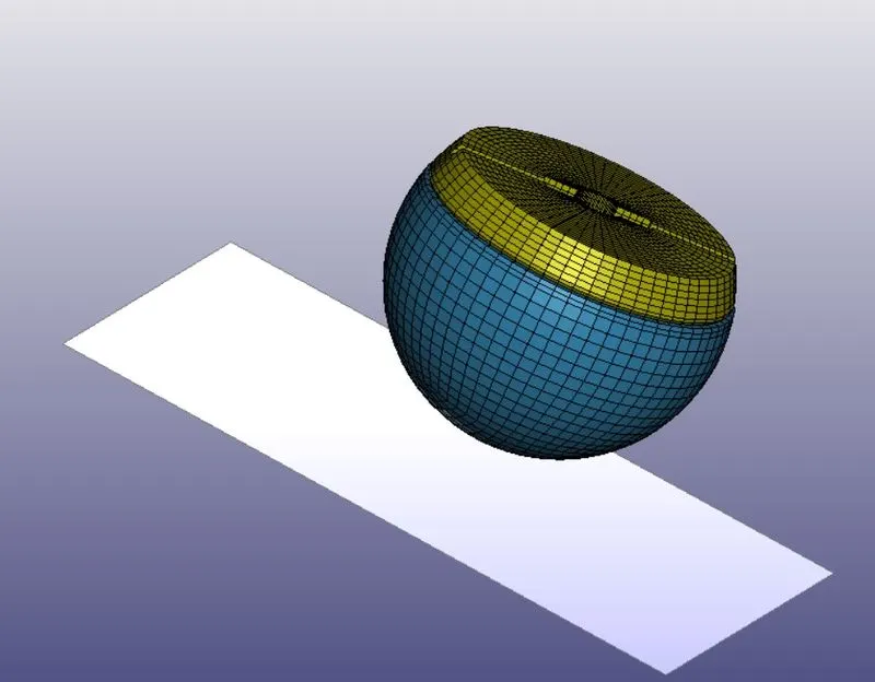
Pepeat the same keywors procedure as in Case(I)
Results:
Von mises stresses and strains are plotted.
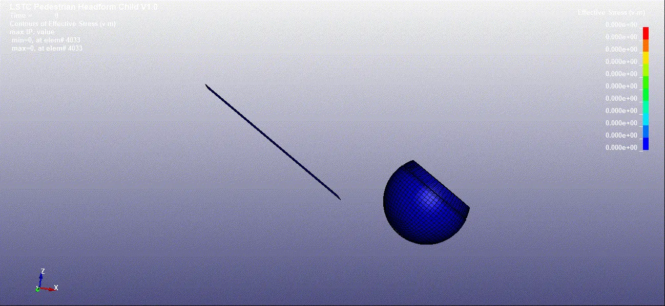
The von mises stress is 34.56 MPa
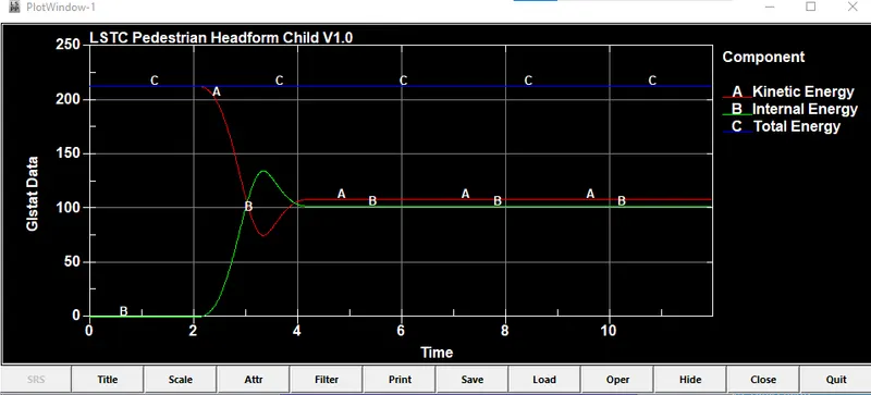
2)The energy distribution is given as,
3)HIC value for this case
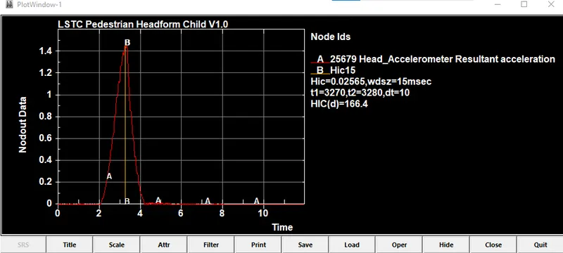
CASE 3:
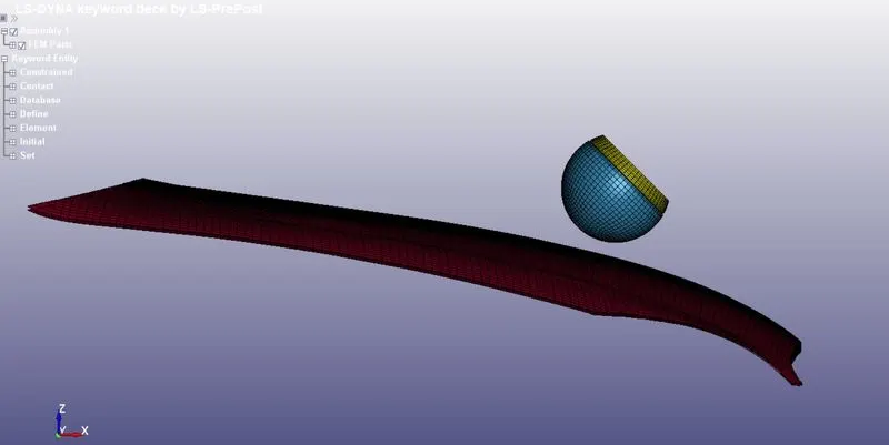
Case 3 is the simulation test for the head foam and the hood model.The rigis wall is replaced with the hood to get a real life simulation. Here, using include and include transform keyword, the two files are imported. Include file segregates the keyword file as per the definition. Here, hood file is selected. After this the head need to rotate by some angle in order to get a real life conditions of the accident. So using transformation, trans ID is defined and applied to the include_ transform file and selected the head foam model.
Procedure:
1)Pepeat the same procedure for Define-Transformation and include Transform for the Pedestrian headfoam and meshed hood file.
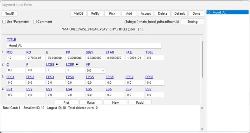
MAT_024_PIECEWISE_LINEAR_PLASTICITY:
The hood model is defined with aluminium material.
2)SECTION ID:
The hood is defined with shell section keyword. The thickness of 2.5 mm is specified.
3)INITIAL VELOCITY:
A box solid is created selecting the head area using create entities>define>box. Then using velocity keyword velocity is given to the head in the direction of negative z as -6 ms. The BOXID is provided with box data we created in previous step.
4)CONTROL TERMINATION:
Termination time of 20 ms is given to the simulation.
Results:
1)Energy Plot:
2)HIC orientation
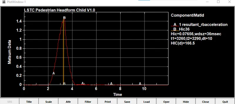
Conclusion:
1)HIC hand calculation:
From the above graph we got the values for time interval t1=2.1ms and t2=15ms. Therefore , the time span t2-t1=20-2.9 = 17.1 ms
Taking in seconds t2-t1=17.1/1000 s
HIC formula:
HIC= [(1/17.1)*91.6*17.1]^2.5*[17.1/1000]
=1373.19
Hence the hand calculated values of HIC are nearly same as that of the solver.
The HIC value in CASE (3) is lower than that in Case(2)
Google Drive link:https://drive.google.com/file/d/1e8DW73hq5E661PZ-rvFnErboBRpygrr3/view?usp=sharing