Week-7 Challenge: DC Motor Control
- Run MATLAB demo ‘Speed control of a DC motor using BJT H-bridge’. Modify the model such that armature current doesn’t shoot up when motor changes direction from forward to reverse.
power electronics:
- power electronics is the application of solid-state electronics to the control and conversion of electric power.
- the power electronics are also called as solid state switches.
- in this model, speed control of DC motor using BJT-H bridge there are two types of power electronic devices.
- the devices are diode and IGBT( insulated gate bipolar transistor).
- the basic power electronic devices are diode, transistor, BJT, IGBT etc..
DIODE:
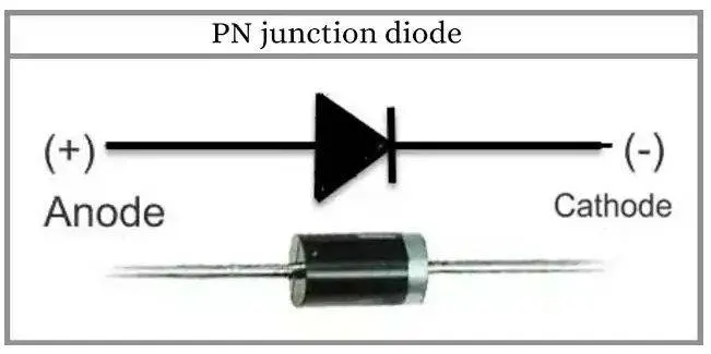
- A diode is a electric current conducting device, which alows the flow of current in one direction.
- Diode allows the current to flow in one direcion i.e.., forward direction and not allows to flow the current in reverse direction.
- these Diodes are called as check valves in electronic version.
- the unidirectional behaviour which is used to turn the alternating current into direct current by rectification.
TRANSISTOR:
- A transistor is a semi cinductor device used to amplify or switch electronic signals and electrical power.
- it is composed of three teminals for connection to an electrical circuit.
- the voltage or currrent applied to one pair of transistor terminal is controlled by another pair of transistor terminal.
- because the controlled output power is higher than the controlled input power which is amplified.
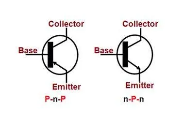
- the transistors are having three terminals emitter, base and collector.
- by doing sandwiching these are classified into p-n-p and n-p-n transistors.
BJT(bipolar junction transistor):
- bi-polar junction transistors is a type of transistor where it uses both electrons and electron holes as charge carriers for charge transfer.
- A bipolar transistor allows a small current injected at one of its terminals to control a much larger current flowing between two other terminals.
- this makes device capable of amplification or switching.
- BJT's are two junctions between p-type and n-type which are regions in a single crystal material.
- the doping can be done in several ways to get different metal pellets to form alloy junctions.
- the diffused transistors along with other components form the integrated circuits for analog and digital functions.
IGBT(insulated-gate bipolar transistor):
- it consists of three-terminal power semiconductor device, which is used for electronic switching.
- it is a fussion between BJT and MOSGET, the output looks like BJT with emitter and collector and the input side which looks like MOSFET.
- it has high efficiency and fast swithing.
- it consists of four layers which are arranged alternatively which are controlled by metal-oxide-semiconductor gate without any regenerative action.
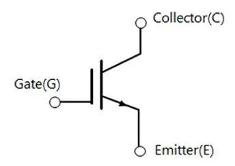
- the device is used amplifing the switching process that has different wave forms with pulse width modulations.
- the structure of IGBT looks similar to that of thyristor or MOS gate, the complete actions are supressed and only transistor action is permitted in entire device operater range.
Speed control of a DC motor using BJT H-bridge:
- the DC motor based are used in industeries due to its variable speed and load characteristics due to its ease of control.
- A chopper based speed controlk systems are used for speed control in electric cars, DC motor regulators etc..
- by using pulse generator a continuous switching of ON and OFF which is connected to the load supply.
- the time period with which the switch ON and OFF operated are called as chopper's ON and OFF state times.
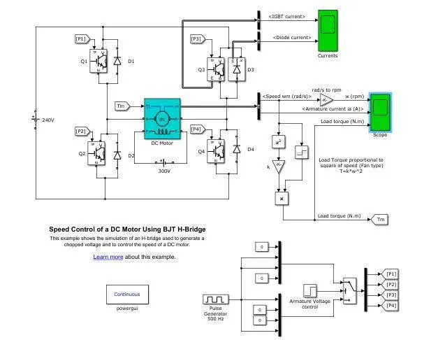
specification of the model:
power = 5 HP
rated speed = 1750 rpm
rated voltage = 240 v
output:
- the model initially runs with a duty cycle of 75 %
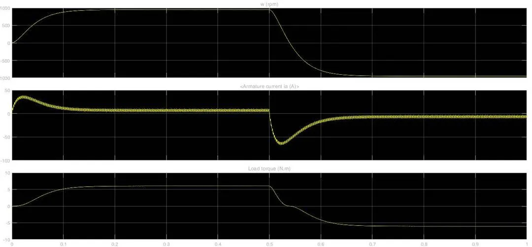
- when the duty cycle is changed from 75 % to 30 %, the initial armature current jump is reduced.
- And at time t = 0.5 sec the positive rotation of the motor is reversed and motor is rotated in reverse direction after the 0.5 sec.
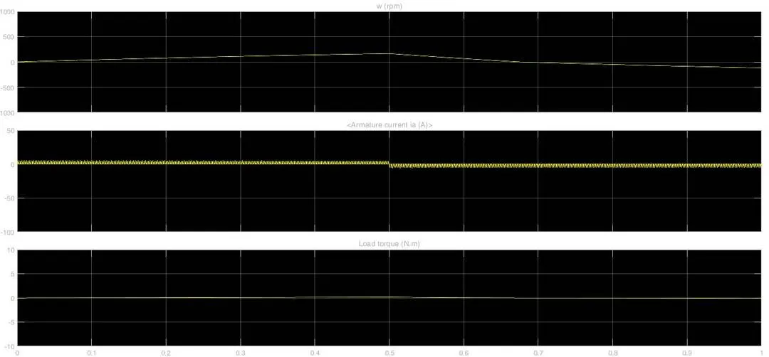
- the by changing the duty cycle we can reduce the armature current jump.
2. comparission of four quadrent chopper DC drive and H- bridge.
The Four-Quadrant Chopper DC Drive (DC7) block:
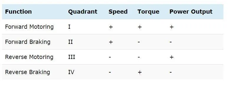
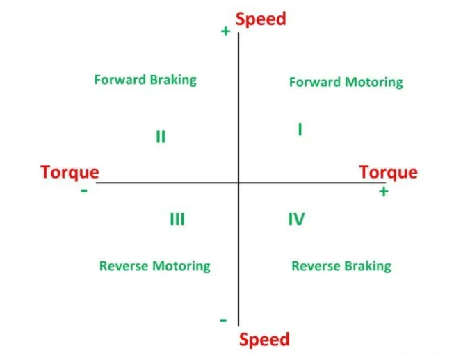
- the four quadrent operation of a DC motor is operated in four quaters i.e.., forward motoring, forward braking, reverse motoring , reverse braking.
- the motor is operated for two motions that is braking and motoring.
- when the motoring mode is activated, the motor converts the electrical energy into mechanical energy for the motion of the vehicle.
- when the braking mode is activated, the motor converts the mechanical energy into electrical energy which is supplied to the battery or the source as a regenrative braking power.
- the product of angular speed and torque is the power supplied are generated by the motor.
- for the multi quadrent system, the sign for speed and torque gives the motoring or braking of the motor.
1 st QUADRENT ( FORWARD MOTORING ):
- For the forward motion of the machine, the torque and the speed are positive in direction.
- the power generated is also positive should be in the forward direction.
- in this quadrent the motor suppling with positive power, which gives the mechanical output by the machine.
2 nd QUADRENT( FORWARD BRAKING ):
- In this quadrent, the troque has negative sign and the speed has positive sign.
- the direction of rotation of speed is always positive which gives the forward motion, and the torque is negative which generates a negative torque and machine acts like a generator which opposes the motion.
- the kinetic energy of the rotating parts is applied in the form of electrical energy which is used to supply the power to battery or source.
3 rd QUADRENT (REVERSE BRAKING ):
- in this quadrent, the torque and speed both are negative sign, which indicates that the power is positive.
- the power out come of the machine is positive but the motion will be in reverse direction.
- the machine itself will rotate in reverse direction.
4 th QUADRENT ( REVERSE BRAKING ):
- in this quadrent, the speed is negative and the torque is positive.
- so overall power output is negative.
- when the motor is rotated in the negative direction,the torque applied will be positive which can produce a power due to its braking effect which is supplied to the battery or source.
comparission of the models:
| H- bridge | Four-Quadrant DC Chopper |
| In H- bridge, only two operations can be performed. | In four- quadrent chopper, four operations can be performed. |
| the two operations are, forward motoring and reverse motoring can be possible. | The four operations are, forward motoring, forward braking, reverse motoring and reverse braking. |
| the operations are performed by reversing the polarity for change in direction. | The reference speed is used to change the direction of the motor rotation. |
| regenerative braking is not possible in H- bridge. | regenerative braking is possible in this four- quadrent DC chopper. |
| power losses are more in H- bridge at the time of switching. | there is no power loss in four quadrent DC chopper. |
3. Make a suitable EV model using DC7 block and make result report?
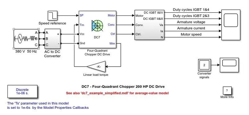
- the above model is used for calculating motor speed, armature current, armature voltage, and functioning of IGBT.
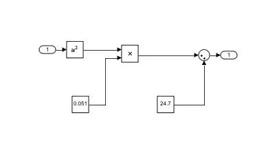
- in this model the linear load torque block is replaced with a subsytem which can change the load- torque characteristics.
- the load- torque equations are used to be:
`T = 24.7 + 0.051(omega^2)`
- by using mathematical block the we can generate the corresponding load- torque characteristics for the motor.
- the AC to DC convertor block is removed and connected with current measurement block and DC voltage supply block to measure the current.
- the drive cycle is connected from workspace having values for time and speed.
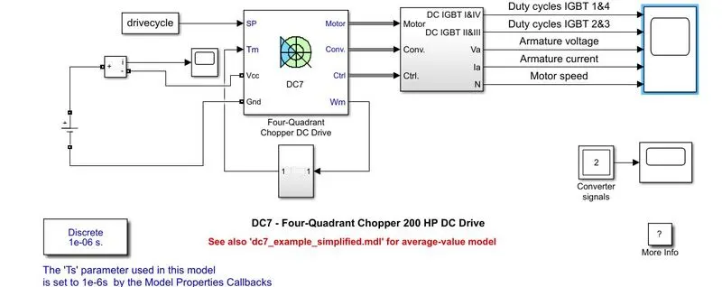
- the simulink model is made to run for 23 sec and the results are evaluated for armature current, armature voltage, motor speed.
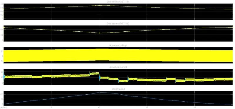
- when the IGBT 1 & 4 starts with a duty cycle of 0.5 i.e.., 50 percent. when the load is increased to maximum of 0.7 at t = 10 sec.
- then IGBT 2 & 3 at the start and end they will have a duty cycle of 0.5 and at the middle at t = 10 sec it will have a t = minimum duty cycle value of 0.3 i.e.., 30 percent.
- there for the duty cycle ratio of IGBT 1 & 4 is inversely proportional to IGBT 2 & 3.
- when the motor speed is increasing, the armature current and armature voltage are increasing and vise-versa.
- At t = 10 sec, the armature voltage and armature current are maximum for the given drive cycle.