Week-7 Challenge: DC Motor Control
1) 1. A. Explain a MATLAB demo model named ‘Speed control of a DC motor using BJT H-bridge’.
B. Comment on the armature current shoot-up from the scope results.
C. Refer to the help section of ‘The Four-Quadrant Chopper DC Drive (DC7) block’. Compare it with the H-bridge model.
A.
- The Bipolar Junction Transistor (BJT) when used for power switching applications, operates as an IGBT.
- When it is conducting (BJT operating in the saturated region), a forward voltage Vf is developed between collector and emitter (in the range of 1 V).
- Therefore, the IGBT block can be used to model the BJT device.
- The IGBT block does not simulate the gate current controlling the BJT or IGBT.
- The switch is controlled by a Simulink signal (1/0).
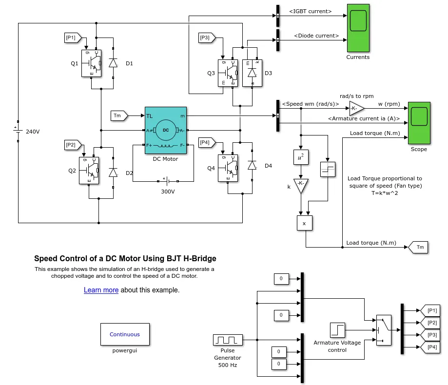
- The DC motor uses the preset model (5 HP 24V 1750 rpm).
- It simulates a fan type load (where Load torque is proportional to square of speed).
- The armature mean voltage can be varied from 0 to 240 V when the duty cycle (specified in the Pulse Generator block) is varied from 0 to 100%.
- The H-bridge consists of four BJT/Diode pairs (BJT simulated by IGBT models).
- Two transistors are switched simultaneously: Q1 and Q4 or Q2 and Q3.
- When Q1 and Q4 are fired, a positive voltage is applied to the motor and diodes D2-D3 operate as free-wheeling diodes when Q1 and Q4 are switched off.
- When Q2 and Q3 are fired, a negative voltage is applied to the motor and diodes D1-D4 operate as free-wheeling diodes when Q2 and Q3 are switched off.
Simulation -
- The motor starts in the positive direction with a duty cycle of 75% (mean DC voltage of 180V).
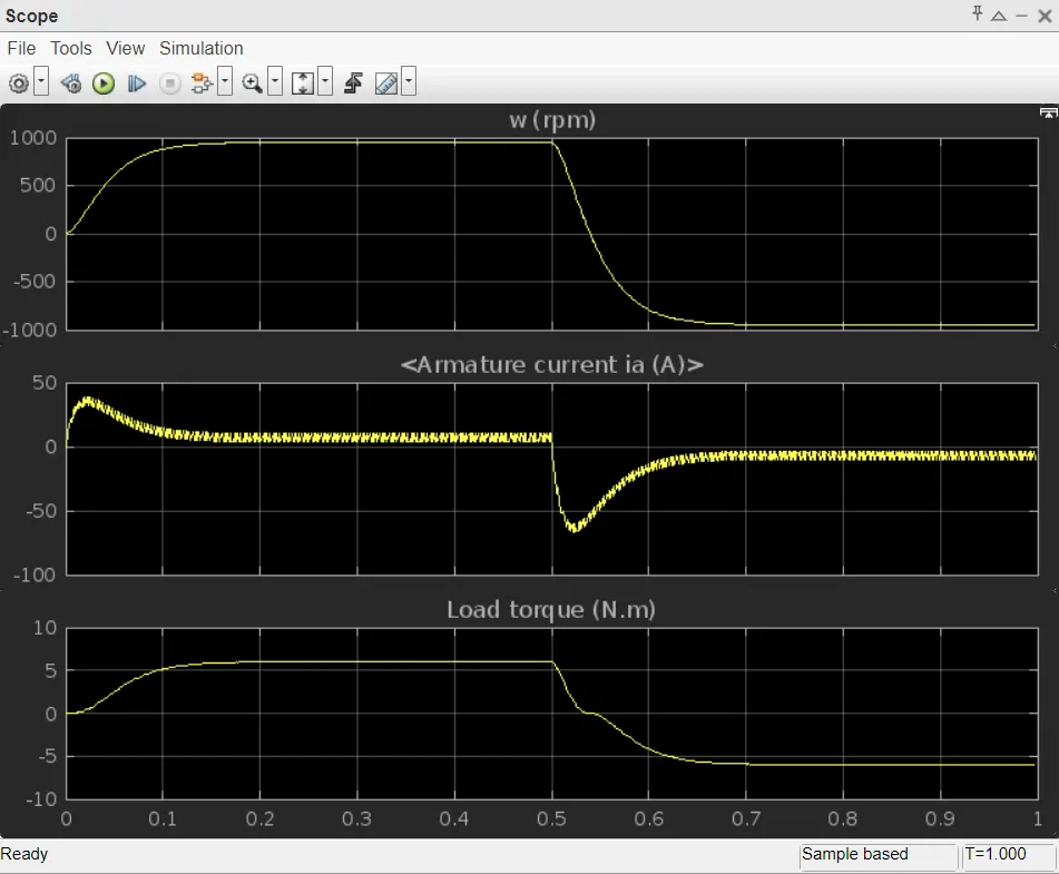
- At t= 0.5 sec., the armature voltage is suddenly reversed and the motor runs in the negative direction.
- Scope shows motor speed, armature current and load torque and 'Currents' shows currents flowing in BJT Q3 and diode D3.
Armature Current Shoot-up -
- At t = 0.5 sec, the armature voltage is reversed and the motor is made to run in reverse direction.
- Due to sudden reversal of voltage the motor armature draws heavy current in order to run the motor in reverse direction.
- This sudden increase in armature current is known as Armature Current Shoot-up.
- The armature current shoot-up can be reduced by decreasing the pulse width.
C. Four-Quadrant Chopper DC Drive (DC-7) Block -
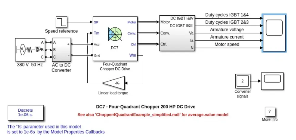
- The 200 HP DC motor is separately excited with a constant 150 V DC field voltage source.
- The armature voltage is provided by an IGBT converter controlled by two PI regulators.
- The converter is fed by a 515 V DC bus obtained by rectification of a 380 V AC 50 Hz voltage source.
- In order to limit the DC bus voltage during dynamic braking mode, a braking chopper has been added between the diode rectifier and the DC7 block.
- The first regulator is a speed regulator, followed by a current regulator.
- The speed regulator outputs the armature current reference (in p.u.) used by the current controller in order to obtain the electromagnetic torque needed to reach the desired speed.
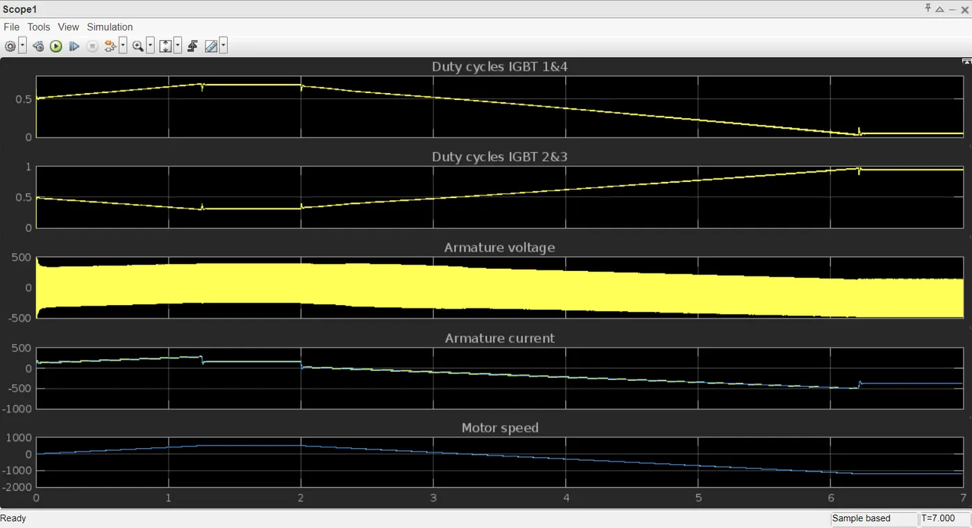
- The speed reference change rate follows acceleration and deceleration ramps in order to avoid sudden reference changes that could cause armature over-current and destabilize the system.
- The current regulator controls the armature current by computing the appropriate duty ratios of the 5 kHz pulses of the four IGBT devices (Pulse Width Modulation).
- For proper system behaviour, the instantaneous pulse values of IGBT devices 1 and 4 are opposite to those of IGBT devices 2 and 3. This generates the average armature voltage needed to obtain the desired armature current.
- In order to limit the amplitude of the current oscillations, a smoothing inductance is placed in series with the armature circuit.
Comparison:
|
DC drive using BJT H-bridge |
DC drive using Four-Quadrant Chopper |
|
Power switches are powered by a 240V DC supply. |
Power switches are powered by a 380V 50Hz AC 3-phase supply which is converted to a 515V DC supply. |
|
Field windings are separately excited by a 300V DC supply. |
Field windings are separately excited by a 150V DC supply. |
|
Works only in forward motoring and reverse motoring. |
Here the D motor operates in all 4 quadrant - forward motoring, reverse motoring, forward braking and reverse braking. |
|
It is just controlling the DC motor speed. |
It is a drive that symbolizes the mechanical and power electronics components. |
|
Efficiency is less. |
Efficiency is more because of being a drive. |
|
Here the torque is proportional to the square of the speed. |
Here the motor is subjected to linear load. Hence the torque is just proportional to speed. |
2. Develop a 2-quadrant chopper using simulink & explain the working of the same with the relevant results. (Refer to article - Multiquadrant operation of motor )
Type C chopper or Two Quadrant class A chopper:
Class-C or Type-C Chopper is a category of chopper which can operate in first as well as second quadrant. This basically means that, the power can either flow from source to load or load to source in this chopper. This kind of chopper is also known as Two Quadrant Class-A chopper.
Operation or Working of Class-C or type C:
As we know that, a Class A and Class B chopper operates in first and second quadrant respectively. Therefore, if we connect both these types of chopper in parallel then it is possible to have chopper operation in first as well as second quadrant. In fact, Class-C or Type-C chopper is obtained by the parallel connection of Class-A and Class-B chopper.
We can notice that chopper CH1, free-wheeling diode (FD) and load are forming Class-A Chopper whereas chopper CH2, D2 and Load are forming Class-B chopper. Both these choppers are connected in parallel. To obtain first quadrant operation we should switch ON chopper CH1 and for getting second quadrant operation we should switch ON chopper CH2. Let us discuss this in detail.
Case 1: When CH1 is switched ON/OFF
When chopper CH1 is switched ON, source Vs directly gets connected to the load and hence, load voltage Vo is equal to source voltage. The direction of load current is from source to load as shown in the circuit diagram which is assumed positive.
When CH1 is switched OFF, the free-wheeling diode FD comes into the circuit as it gets forward biased and hence shorts the load. Therefore, the output voltage Vo becomes zero. However, the io continues to die down through the FD and L in the same direction as shown in circuit diagram. Thus, the average output voltage Vo and current Io are positive and hence operation of chopper is in first quadrant.
Case 2: When CH2 is switched ON/OFF
When chopper CH2 is switched ON, load DC source E drives current through CH2 and load. The direction of this current io will be opposite to that shown in circuit diagram and hence is assumed negative. Output voltage Vo is zero during this time. When CH2 is made OFF, diode D2 gets forward biased and hence the current into the source from the load. The output voltage is Vs in this time as the load is connected to the source through D2 during OFF time of chopper CH2. Thus, the load current is always negative i.e. operation of chopper is within second quadrant.
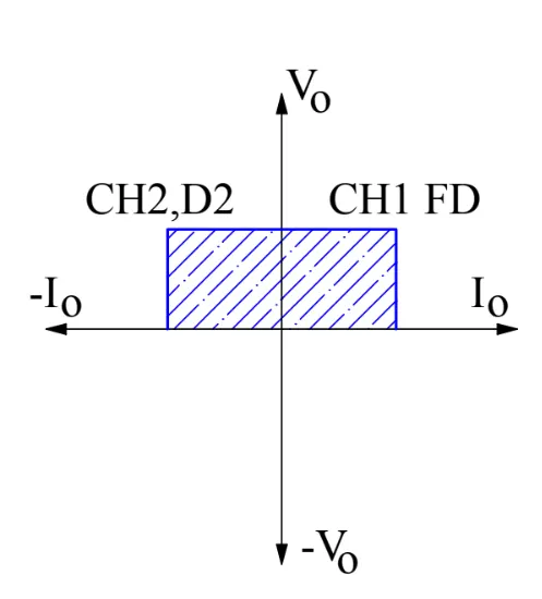
The average load voltage is always positive but the average load current may be positive or negative. Therefore, power flow may be from source to load (first quadrant operation) or load to source (second quadrant operation). The operating region of Class-C or Type-C chopper is shown below by hatched area.
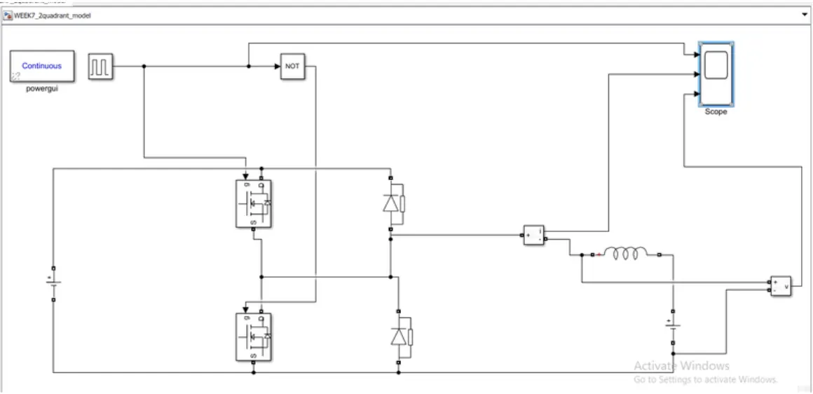
The simulink model for the 2 quadrant chopper is shown below -
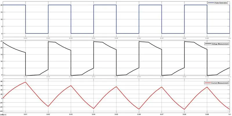
Hence, we could see clearly that the voltage is always positive but the current becomes both positive and negative. Hence, the Type C chopper is simulated and verified.
3. Explain in a brief about operation of BLDC motor.
A Brushless DC (BLDC) motor is an electric motor that operates using direct current (DC) electricity. It is a type of synchronous motor, meaning the magnetic field produced by the stator and the rotor rotate at the same frequency.
Here's a brief explanation of the operation of a BLDC motor:
- Stator: The stator is the stationary part of the motor and contains coils of wire that are connected to the power supply. These coils create a magnetic field when an electric current passes through them.
- Rotor: The rotor is the rotating part of the motor, usually made up of permanent magnets. The interaction between the magnetic fields of the stator and rotor creates a torque that causes the rotor to turn.
- Electronic Commutation: Unlike brushed DC motors that use brushes and a commutator to switch the direction of current in the rotor windings, BLDC motors use electronic commutation. This means that the direction of current in the stator windings is controlled by electronic switches (transistors) in the motor controller.
- Hall Sensors: Some BLDC motors incorporate Hall effect sensors on the stator. These sensors detect the position of the rotor magnets and provide feedback to the motor controller. This feedback helps in determining the timing of the electronic commutation, ensuring that the magnetic fields are always aligned for optimal performance.
- Motor Controller: The motor controller is a crucial component that determines when to switch the direction of current in the stator windings. It receives feedback from sensors (if used) and controls the power supply to the stator coils to maintain the rotation of the rotor.
- Phases: BLDC motors typically have three phases, and the current in each phase is controlled to create a rotating magnetic field. The rotor follows this field, resulting in smooth and efficient rotation.
- Advantages: BLDC motors offer several advantages, including higher efficiency, longer lifespan, and lower maintenance compared to brushed DC motors. They are widely used in various applications such as electric vehicles, computer disk drives, and household appliances.
In summary, the operation of a BLDC motor involves the generation of a rotating magnetic field through electronic commutation, leading to the rotation of the rotor. The use of electronic control and absence of brushes contribute to the efficiency and reliability of BLDC motors.