Week-7 Challenge: DC Motor Control
1)Speed control of a DC motor using BJT H-bridge.
Objective:
A. Explain a MATLAB demo model named ‘Speed control of a DC motor using BJT H-bridge’.
B. Comment on the armature current shoot-up from the scope results.
C. Refer to the help section of ‘The Four-Quadrant Chopper DC Drive (DC7) block’. Compare it with the H-bridge model.
Model:
pulse generator:
/
Here in the model four switches are used thus four pulse signals are generated accordingly.
A)Working of H-bridge model:
- Here H-bridge DC chopper circuit is designed to control the speed of the motor.
- IGBT acts as BJT in power switching devices.
- Four IGBT switches are used for inverting the DC voltage 0 to 240 v supply.The current flows from collector(C) to emitter(E).
- The gate are controlled by the pulses(0 and 1) according to the armature voltge of motor given by pulse generator.
- This image shoes the voltage value given from initial to final during the step time.According to the pulses on and off the voltage supplied to the IGBT's.
- Here four switches are used Q1,Q2,Q3,Q4. Pulses P1,P2,P3,P4 are conected with corresponding switches.
- In first state, Q1 and Q4 are closed by giving 1V to IGBT'S,current from battery passes through Q1 and Q4.Diode D2,D3 are used as free wheeling diode in this state.In this case Forward motoring and forward breaking are held.
- In Second state,Q2 and Q3 are closed by giving 1V to IGBT's,current from battery passes through Q2 and Q3.Diode D1,D4 are used as free wheeling diode in this stateIn this case reverse motoring and reverse breaking are held.The current direction change its direction in this state.
- Both the states are occuring in 0.5 seconds in their sample time.Thus DC supply converted and feeded to the armature of the motor.
- Here free wheeling diodes are used as a safety purpose of this inverter circuit as when the flow of current on low values protects the circuit and machine by feed backing the current or in high voltage fluctuvations voltage get splited as protection to the motor and circuit components.
- In motor operation, armature terminals are connected with a 240V along the inverter circuit and field windings are connected with 300 V DC suppy to act as a electro magnet for the motor.
- The load torque is given as mechanical input to the motor for its referance.
- Thus through this magnetic fields generated, variable current carring conductors in rotor armature produces forces according to fleming left hand rule principle. Thus the motor starts to rotate.
- Here run this demo model and study the results from scopes.
Result:
From the result scope we are getting,
Speed of motor:
- Initially increases to 0 to nearly 900 rpm upto 0.5 secs(Forward motoring action takes place).
- Then speed reduces to 0 rpm(Forward dynamic breaking action takes place).
- Then speed increases from 0 to -900 rpm at upto 1 sec( Reverse motoring action takes place).
- Then reverse dynasmic breaking occurs(Not shown in scope).
Load torque of motor:
- Initially torque increase from 0 to 0.5 secs in forward motoring action.
- Then torque reduces to 0 Nm in forward dynamic breaking mode.
- Then torque increases in reverse direction in reverse motoring action upto 1 sec.
- Again torque reduce to zero.(Not shown in scope).
B) Armature current shoot up in motor.
Here the initial current shoot up is due to sudden increase in voltage which inurns regulated by duty cycle.In this case motor driven in 75% of duty cycle.(i.e) 0.75*240= 180 V.
We can change the duty cycle to 50%(120 V) and seen the results as,
Sudden shoot up canceled in starting condition but slight shootup after 0.5 sec in reverse motoring condition.
Again changing duty cycle to say 35%,we get the result as,
The shoot up of current get dimlished on both the ends.
Conclusion:
Thus to reduce the shootup armature currents we have to change the duty cycle gradually from 0 to 100%,that inturns increases voltage gradually and speed also changes accordingly.
C) Comparing ‘The Four-Quadrant Chopper DC Drive (DC7) block’ with H bridge model:
Block:
Connections:
Inputs and outputs:
Armature voltage ,speed referance ,motor torque referance are given as inputs.
Motor,convertor,controller,motor angular speed are get as outputs.
Working:
- Here Four Igbt switches are used.
- Here pulses are given from PI current controller, that controles the pulses by comparing armature current measurement and current referance.
- Current referance can be generated by using regulation switch in that torque referance and PI speed controller pulses,that internally compared by speed of motor and refrance speed given as input.
- Mainly speed controlled by current controller.
- In this case Four quadrant operations are performed.
- Forward motoring mode,forward regenerative breaking mode: Q1,Q4 are on and Q2,Q3 are in off.
- Reverse motoring mode,reverse regenerative breaking mode: Q2,Q3 are on and Q1,Q4 are in off.
Comparisons:
- In DC7 chopper model speed controlled by varying current pulses from PI current controller and in H-brige model speed controlled by varying duty cycles voltages.
- Here regenerative breaking in occring while in H-bridge model breaking is occured by changing polarity of current flow,dynamic breaking occurs in it.
- In four quadrant DC chopper model smoothing inductance is used for smooth increase and decrease in current flow which inturns controlling the motor speed smoothly,while in H-bridge it is not present.
- Here the operation is discreat and in H-bridge model it is continuous.
- Hence 4 quadrant DC choppers are used mostly in electric vehicles.
2. Develop a 2-quadrant chopper using simulink & explain the working of the same with the relevant results
ANS:
CIRCUIT DIAGRAM FOR TWO QUADRANT CHOPPER:
two quadrant chopper is also called as type c chopper. Type C chopper is obtained by connecting type –A and type –B choppers in parallel. We will always get a positive output voltage V0 as the freewheeling diode FD is present across the load. When the chopper is on the freewheeling diode starts conducting and the output voltage v0 will be equal to Vs . The direction of the load current i0 will be reversed. The current i0 will be flowing towards the source and it will be positive regardless the chopper is on or the FD conducts. The load current will be negative if the chopper is or the diode D2 conducts. We can say the chopper and FD operate together as type-A chopper in first quadrant. In the second quadrant, the chopper and D2 will operate together as type –B chopper.
The average voltage will be always positive but the average load current might be positive or negative. The power flow may be life the first quadrant operation ie from source to load or from load to source like the second quadrant operation. The two choppers should not be turned on simultaneously as the combined action my cause a short circuit in supply lines. For regenerative braking and motoring these type of chopper configuration is used.
TWO QUADRANT CHOPPER MODEL USING SIMULINK:
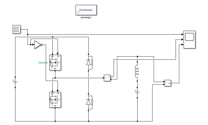
let us take two mosfet blocks and diodes blocks and connect it as shown in circuit diagram.
the dc voltage source is connected as shown.
let the voltage of dc voltage source be 24 volts.
let us consider an series RLC branch block and select inductor L . thus block works as a load.
to consider LE load ie motor load , and dc voltage source of 12 volt is also connected in series with inductor.
The pulse generator block is used to create gate pulse.
the not gate is used in the model so that the two mosfet will not get closed at the same time otherwise short circuit will occur .due to use of not gate , when one mosfet is ON the other mosfet will get off and when other mosfet is ON the first mosfet will get off .
The amplitude of pulse generator is kept 10 so that we can clearly see the pulses at scope and let period be 0.02 seconds and let pulse weidth be 50%
SCOPE RESULT:
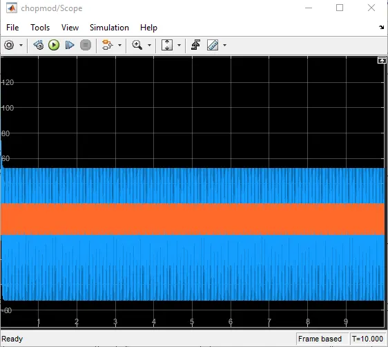
the voltage waveform is not going less than zero . the minimum value of voltage is zero and maximum value is always in the positive direction.
however in current waveform , the current increases and decreases. the current may be positive as well as negative.
and the pulse amplitude is 10 thus from pulse waveform we can see that the pulse amplitude is 10.
3)
BLDC MOTOR
Brushless DC electric motors also known as electronically commutated motors .A brushless DC motor (known as BLDC) is a permanent magnet synchronous electric motor which is driven by direct current (DC) electricity and it accomplishes electronically controlled commutation system (commutation is the process of producing rotational torque in the motor by changing phase currents through it at appropriate times) instead of a mechanically commutation system. BLDC motors are also referred as trapezoidal permanent magnet motors.
Unlike conventional brushed type DC motor, wherein the brushes make the mechanical contact with commutator on the rotor so as to form an electric path between a DC electric source and rotor armature windings, BLDC motor employs electrical commutation with permanent magnet rotor and a stator with a sequence of coils. In this motor, permanent magnet (or field poles) rotates and current carrying conductors are fixed.
The armature coils are switched electronically by transistors or SCR at the correct rotor position in such a way that armature field is in space quadrature with the rotor field poles. Hence the force acting on the rotor causes it to rotate. Hall sensors or rotary encoders are most commonly used to sense the position of the rotor and are positioned around the stator. The rotor position feedback from the sensor helps to determine when to switch the armature current.
This electronic commutation arrangement eliminates the commutator arrangement and brushes in a DC motor and hence more reliable and less noisy operation is achieved. Due to the absence of brushes BLDC motors are capable to run at high speeds. The efficiency of BLDC motors is typically 85 to 90 percent, whereas as brushed type DC motors are 75 to 80 percent efficient. There are wide varieties of BLDC motors available ranging from small power range to fractional horsepower, integral horsepower and large power ranges.
In this motor, the permanent magnets attach to the rotor. The current-carrying conductors or armature winding are located on the stator. They use electrical commutation to convert electrical energy into mechanical energy.
The main design difference between a brushed and brushless motors is the replacement of mechanical commutator with an electric switch circuit. A BLDC Motor is a type of synchronous motor in the sense that the magnetic field generated by the stator and the rotor revolve at the same frequency.
Brushless motor does not have any current carrying commutators .The field inside a brushless motor is switched through an amplifier which is triggered by the commutating device like an optical encoder.
BLDC motors can be constructed in different physical configurations. Depending on the stator windings, these can be configured as single-phase, two-phase, or three-phase motors. However, three-phase BLDC motors with permanent magnet rotor are most commonly used.