Week-7 Challenge: DC Motor Control
1) A) The MATLAB demo model named Speed control of a DC motor using BJT H-bridge explanation is as follows:
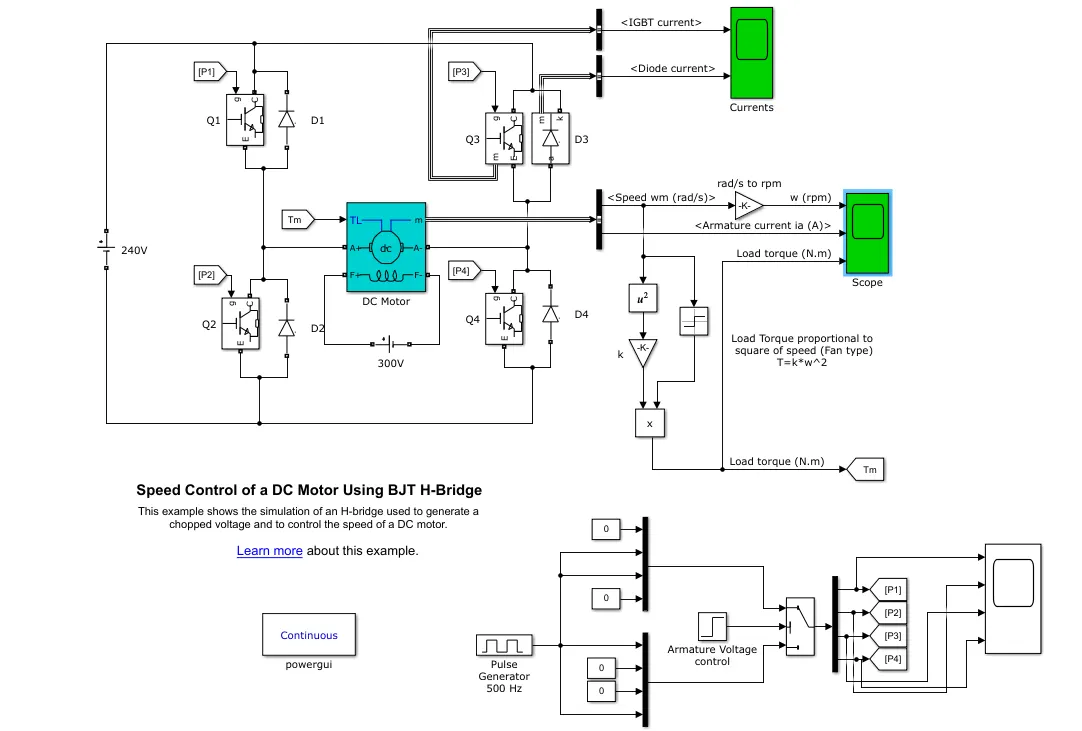
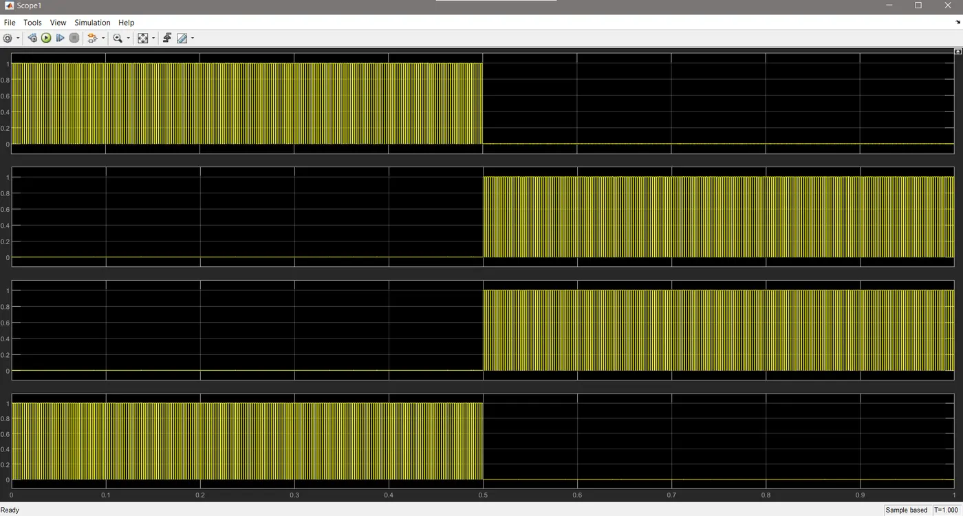
The Bipolar Junction Transistor (BJT) is used for power switching. The H-bridge consists of four BJT/Diode pairs. Two transistors are switched simultaneously: Q1 and Q4 or Q2 and Q3. When Q1 and Q4 are fired, a positive voltage is applied to the motor and diodes D2-D3 operate as free-wheeling diodes when Q1 and Q4 are switched off. When Q2 and Q3 are fired, a negative voltage is applied to the motor and diodes D1-D4 operate as free-wheeling diodes when Q2 and Q3 are switched off. The switching of Q1,Q2,Q3, and Q4 is shown below.
B) The armature current shoot-up from the scope results is shown below:
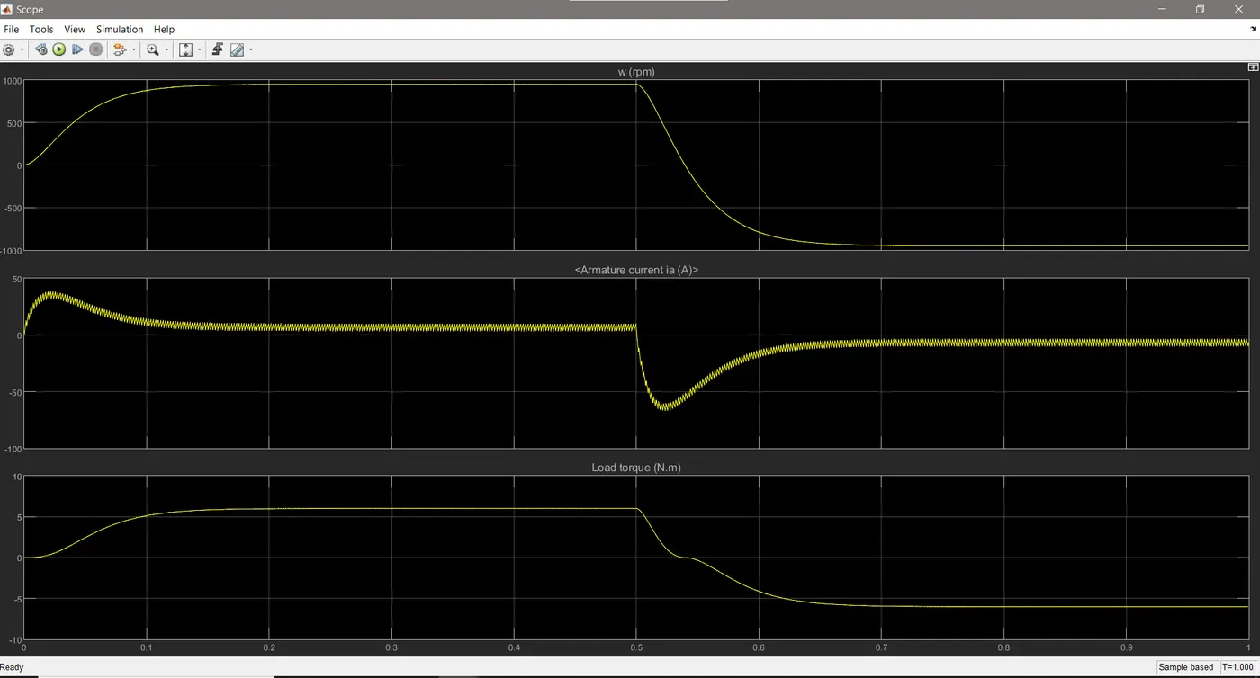
From the above switching we could see that the current and speed is positive when Q1 and Q3 is ON (0 to 0.5) and it is high due the starting of the motor. Then when Q2 and Q4 condcts (0.5 to 1) the current and speed are in negative which shows that the operation of the motor is in reverse motoring.
C) The Four-Quadrant Chopper DC Drive (DC7) block model Vs H-bridge model is as follows:
Four- Quadrant chopper DC Drive (DC7) model
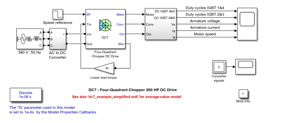
To convert this DC7 model to a respective EV model we need to make few changes,
- We need to replace the AC to DC converter and the rectifier of 380V 50HZ with a DC source battery and current sensor in series with the DC source battery.
- We need to replace the AC battery source with a DC battery to simulate the working of an electric vehicle.
Comparison:
|
Four-Quadrant Chopper DC Drive |
H-bridge model |
|
To change the motor direction the polarity is changed |
To change the motor direction the current signal has to be interrupted. |
|
It has broader torque and power output ranges |
It uses single pulse generator which gives narrow torque and power output range. |
|
In this the current has chopped values. |
In this the current has continuous values. |
|
Regenerative braking is possible |
Regenerative braking is not possible |
2) A 2-quadrant chopper opreation is as follows:
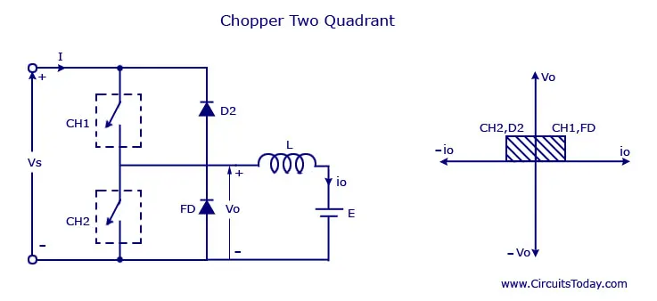
Type C chopper is obtained by connecting type –A and type –B choppers in parallel. We will always get a positive output voltage V0 as the freewheeling diode FD is present across the load. When the chopper is on the freewheeling diode starts conducting and the output voltage v0 will be equal to Vs. The direction of the load current i0 will be reversed. The current i0 will be flowing towards the source and it will be positive regardless the chopper is on or the FD conducts. The load current will be negative if the chopper is or the diode D2 conducts. We can say the chopper and FD operate together as type-A chopper in first quadrant.
In the second quadrant, the chopper and D2 will operate together as type –B chopper. The average voltage will be always positive but the average load current might be positive or negative. The power flow may be life the first quadrant operation ie from source to load or from load to source like the second quadrant operation. The two choppers should not be turned on simultaneously as the combined action my cause a short circuit in supply lines. For regenerative braking and motoring these type of chopper configuration is used.
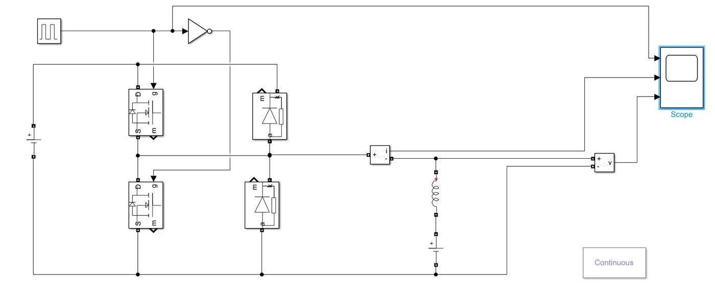
Simulation of 2 quadrant operation:
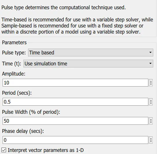
Pulse generator parameters:
Considering the
The blocks used to for the simulink :
- PowerGUI
- Pulse Generator
- DC Voltage Source 1 - 24V
- DC Voltage Source 2 - 12V
- NOT Operator
- Mosfet
- Diode
- Current Measurement
- Series RLC Branch with only inductor
- Voltage Measurement
- Scope
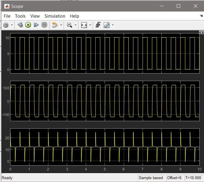
Results:
3) BLDC Motor :
A brushless DC motor (known as BLDC) is a permanent magnet synchronous electric motor which is driven by direct current (DC) electricity and it accomplishes electronically controlled commutation system (commutation is the process of producing rotational torque in the motor by changing phase currents through it at appropriate times) instead of a mechanically commutation system. BLDC motors are also referred as trapezoidal permanent magnet motors. Unlike conventional brushed type DC motor, wherein the brushes make the mechanical contact with commutator on the rotor so as to form an electric path between a DC electric source and rotor armature windings, BLDC motor employs electrical commutation with permanent magnet rotor and a stator with a sequence of coils. In this motor, permanent magnet (or field poles) rotates and current carrying conductors are fixed.
Operation of BLDC Motor :
BLDC motor works on the principle similar to that of a conventional DC motor, i.e., the Lorentz force law which states that whenever a current carrying conductor placed in a magnetic field it experiences a force. As a consequence of reaction force, the magnet will experience an equal and opposite force. In case BLDC motor, the current carrying conductor is stationary while the permanent magnet moves.
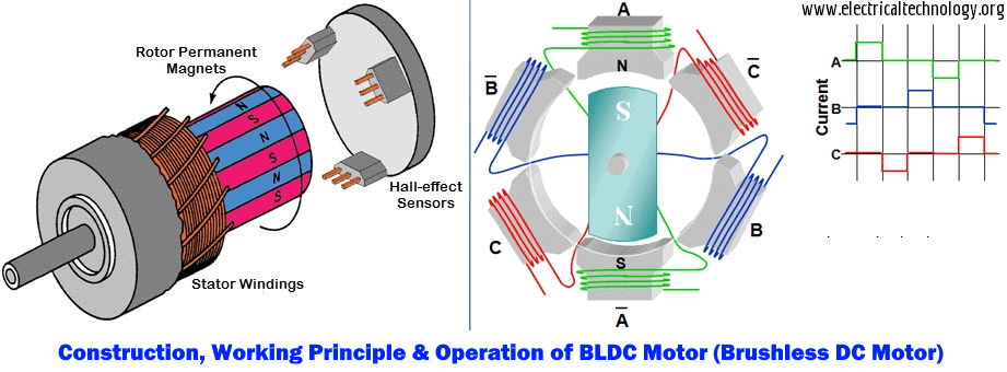
When the stator coils are electrically switched by a supply source, it becomes electromagnet and starts producing the uniform field in the air gap. Though the source of supply is DC, switching makes to generate an AC voltage waveform with trapezoidal shape. Due to the force of interaction between electromagnet stator and permanent magnet rotor, the rotor continues to rotate. The motor stator is excited based on different switching states. With the switching of windings as High and Low signals, corresponding winding energized as North and South poles. The permanent magnet rotor with North and South poles align with stator poles causing motor to rotate.
The motor produces torque because of the development of attraction forces (when North-South or South-North alignment) and repulsion forces (when North-North or South-South alignment). By this way motor moves in a clockwise direction.
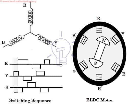
The motor continuous rotation depends on the switching sequence around the coils. Based on this signal from sensor, the controller decides particular coils to energize. Hall-effect sensors generate Low and High level signals whenever rotor poles pass near to it. These signals determine the position of the shaft.