Week-7 Challenge: DC Motor Control
Objective: Simulation of all four-quadrant operation of chopper using MATLAB Simulink.
Abstract:
If the semiconductor devices in power converter circuits are arranged appropriately, it can be used to control a variable DC drive. The speed and torque control of a DC motor can be forced by making it operative with the help of an H Bridge circuit in its different mode of operation. Here a chopper circuit is studied for the different modes of operation of a motor. We can classify chopper circuits according to their working in any of these four quadrants as type A, type B, type C, type D and type E. This project emphasis on simulation of all four-quadrant operation of chopper using MATLAB Simulink.
To begin with, a chopper-based DC motor drive model is developed in Simulink and the multi quadrant operation is explained
Introduction
The DC motor is used in many industrial applications requiring variable speed and load characteristics due to its ease of control. A chopper drive-based speed control is widely preferred as far as speed control is concerned. Choppers are mostly applied in electric cars, conversion of wind and solar energy, and DC motor regulators. A chopper uses the high speed to connect and disconnect from a source load. A fixed DC voltage is applied intermittently to the source load by continuously triggering the power switch ON/OFF. The period for which the power switch stays ON or OFF is referred to as the chopper’s ON and OFF state times, respectively.
The four-quadrant chopper is a chopper which can operate in all the four quadrants. The power can flow either from source to load or load to source in this chopper. In the first quadrant, a Class-E chopper acts as a Step-down chopper whereas in the second quadrant it behaves as a Step-up chopper. This type of chopper is also known as a Class-E or Type-E chopper. This article describes the working principle and operation of a Class-E chopper with the help of a circuit diagram.
What is a chopper?
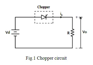
A dc‐to‐dc converter, also known as dc chopper, is a static device which is used to obtain a variable dc voltage from a constant dc voltage source. Choppers are widely used in trolley cars, battery-operated vehicles, traction motor control, control of large numbers of dc motors, etc. They are also used as dc voltage regulators. Choppers are of two types: (1) Step‐down choppers, and (2) Step‐up choppers. In step‐down choppers, the output voltage will be less than the input voltage, whereas in step‐up choppers output voltage will be more than the input voltage
Chopper-Fed DC Motor Drive
D.C motor is considered a SISO (Single Input and Single Output) system having torque/speed characteristics compatible with most mechanical loads. This makes a DC motor controllable over a wide range of speeds by proper adjustment of the terminal voltage
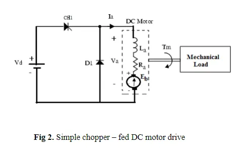
A simple chopper – fed DC motor drive is shown in Fig.2. The basic principle behind DC motor speed control is that the output speed of a DC motor can be varied by controlling armature voltage for speed below and up to rated speed keeping field voltage constant. The armature voltage can be controlled by controlling the duty cycle of the converter (here the converter used is a DC chopper)
Two Quadrant Chopper
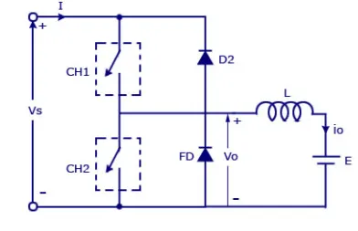
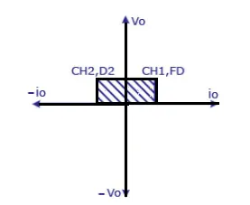
In this type of Chopper, the average voltage will be always positive but the average load current might be positive or negative. The two Switches CH1 and CH2 should not be turned on simultaneously as the combined action may cause a short circuit in supply lines. For regenerative braking and motoring these type of chopper configuration is used.
We will always get a positive output voltage V0 as the freewheeling diode FD is present across the load. When the chopper CH1 is on the current flows from source to load. The inductor stores energy. When Ch1 turn OFF the freewheeling diode starts conducting and the output voltage v0 will be equal to Vs. The direction of the load current i0 will be reversed. The current i0 will be flowing towards the source. The load current will be negative when the CH2 is on. The current completes its path through diode D2.
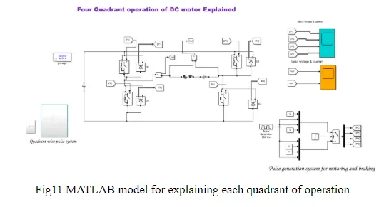
For discussing all quadrant operation of DC motor, we go for Type E or the four-quadrant chopper consisting of four semiconductor switches and four diodes arranged in antiparallel. The 4 choppers are numbered according to which quadrant they belong. Their operation will be in each quadrant and the corresponding chopper only is active in its quadrant.
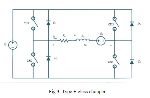
Multiquadrant operation of DC motor explained with MATLAB model
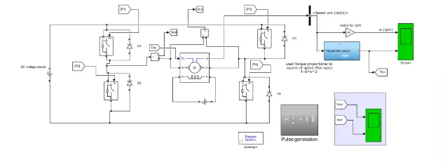
Fig.5 MATLAB model of speed control of DC Motor
Model description
The four-quadrant chopper model was developed in Simulink with ideal switches and diodes. A DC machine was connected as the load. The torque of the motor was measured as in closed-loop control. The pulse generation subsystem has the pulse generator giving switching pulses to the four switching elements as in order. The armature voltage provided is 240V and the field voltage is given to be 300VDC as per the Standard specification of the present model (5HP 240V,1750RPM 300V) The switches are triggered with 50 %duty cycles. At the output side, the speed output in rad/s is converted to its equivalent speed in RPM. Closed-loop control of torque of the motor is implemented.
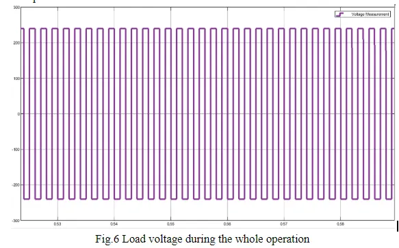
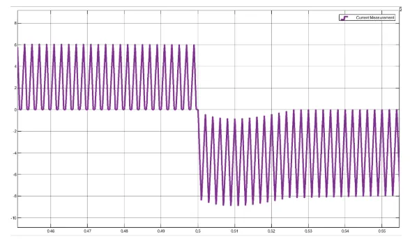
Fig.7 Load current during the whole operation
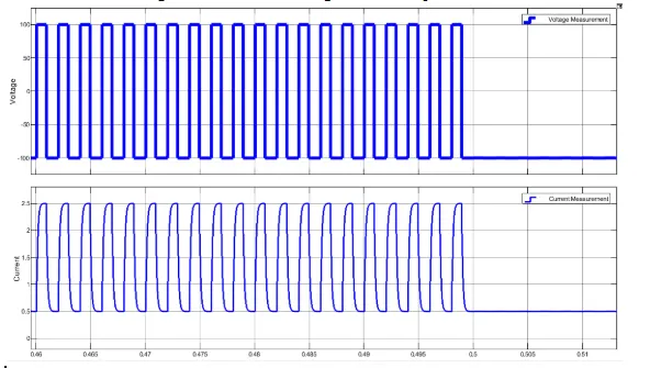
Fig.8 Load current and Load voltage Motoring operating
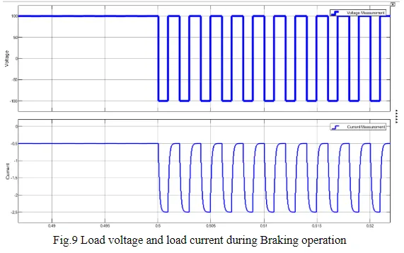
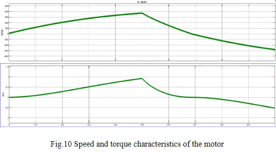
First Quadrant Operation:
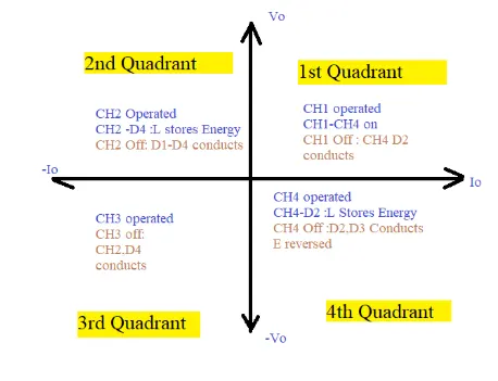
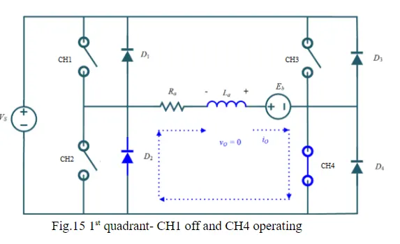
For first quadrant operation, CH4 is kept ON, CH3 is kept OFF and CH1 is operated. When both CH1 & CH4 are ON simultaneously, the load gets directly connected to the source and hence the output voltage becomes equal to the source voltage. This essentially means that vo = vs. It may be noted that the load current flows from source to load as shown by the direction of io.
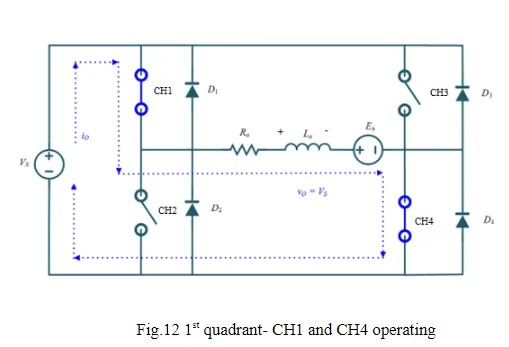
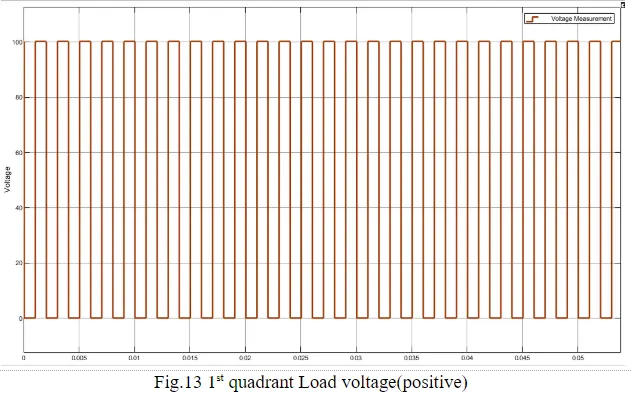
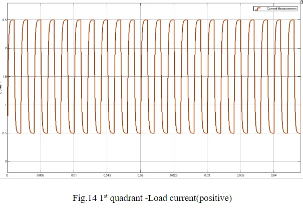
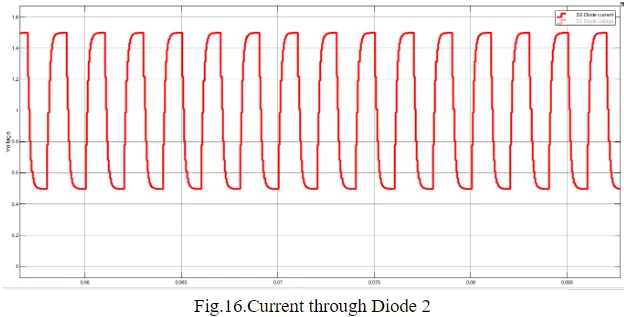
When CH1 is switched OFF, the load current freewheels through CH4 and D2. During this period, the load voltage and current remain positive. Thus, both the output voltage vs and load current io are positive and hence, the operation of the chopper is in the first quadrant. It may be noted that Class-E chopper operates as a step-down chopper in this case.
Second Quadrant Operation:
To obtain second quadrant operation, CH2 is operated while keeping the CH1, CH3 & CH4 OFF. When CH2 is ON, the DC source in the load drives current through CH2, D4, E and L. Inductor L stores energy during the on period of CH2.
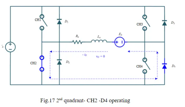
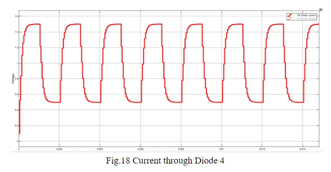
When CH2 is turned OFF, the current is fed back to the source through D1, D4. It should be noted at this point that (E+Ldi/dt) is more than the source voltage Vs. As load voltage Vo is positive and Io is negative, it is the second quadrant operation of the chopper. Since the current is fed back to the source, this simply means that load is transferring power to the source.
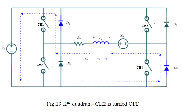
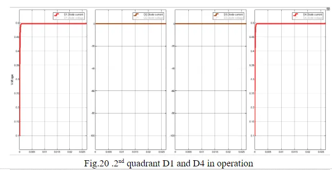
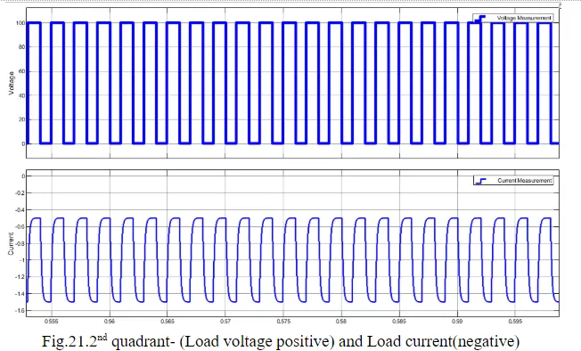
In the second quadrant, configuration operates as a step-up chopper.
Third Quadrant Operation:
To obtain the third quadrant operation, both the load voltage and load current should be negative. The current and voltage are assumed positive if their direction matches with what shown in the circuit diagram. If the direction is opposite to what shown in the circuit diagram, it is considered negative. One important thing to notice is that the polarity of emf E in load must be reversed to have third quadrant operation. Circuit diagram of Class-E chopper for third quadrant operation is shown below
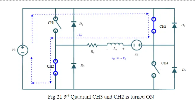
The polarity of Load emf E reversed
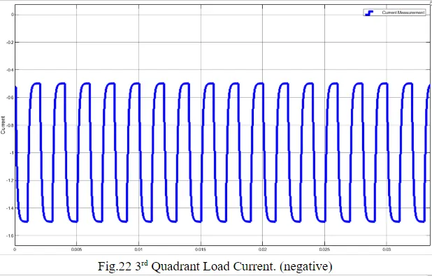
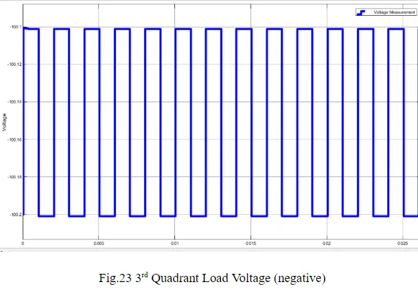
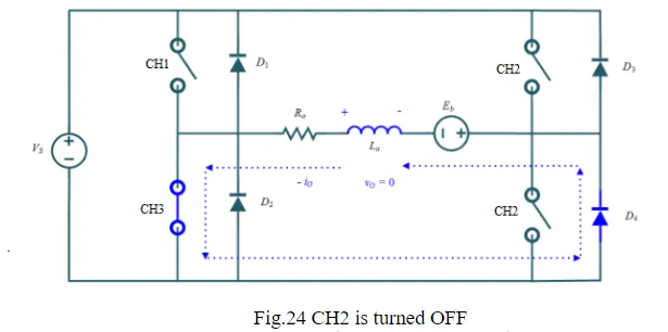
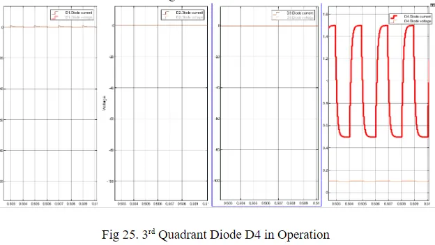
For third quadrant operation, CH1 is kept off, CH2 is kept ON and CH3 is operated. When CH3 is ON, the load gets connected to the source and hence load voltage is equal to source voltage. But carefully observe that the polarity of load voltage vo is opposite to what shown in the circuit diagram. Hence, vo is assumed negative. Let us now see what the status of the load is current io. It may be seen that io is flowing in the direction opposite to shown in the circuit diagram and hence negative.
Now, when CH3 is turned OFF, the negative load current freewheels through the CH2 and D4. In this manner, vo and io both are negative. Hence, the chopper operates in the third quadran
Fourth Quadrant Operation:
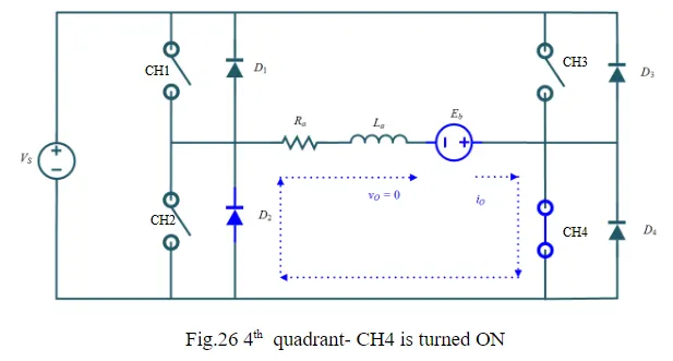
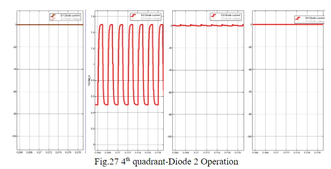
To obtain fourth quadrant operation, CH4 is operated while keeping CH1, CH2 and CH3 OFF. The polarity of load emf E needs to be reversed in this case too like third quadrant operation.
When CH4 is turned ON, positive current flows through CH4, D2, L and E. Inductance L stores energy during the time CH4 is ON.
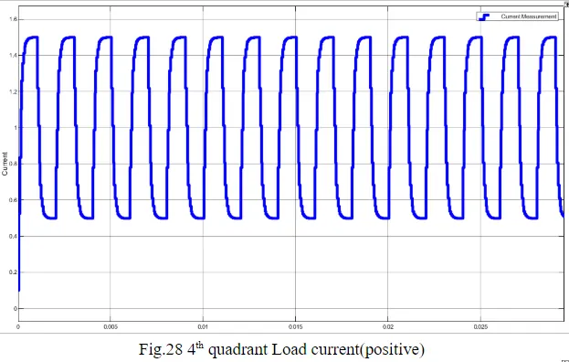
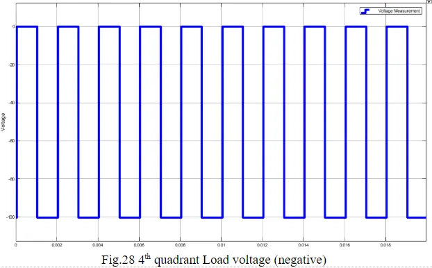
When CH4 is made OFF, the current is fed back to the source through diodes D2, D3. Here load voltage is negative, but the load current is always positive. This leads to chopper operation in the fourth quadrant. Here, power is fed back to the source from the load and the chopper acts as a step-up chopper
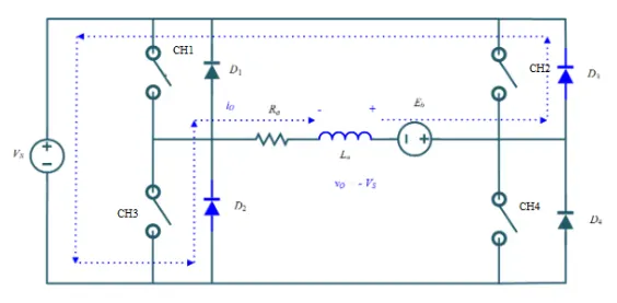
Fig.29 4th quadrant- CH4 is turned OFF
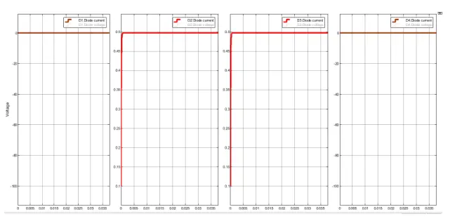
Fig.30 4th quadrant-Diode 2 & Diode 3 Operation
Conclusion
The operation of a four-quadrant chopper or Class-E chopper is summarized in the figure below