Week-7 Challenge: DC Motor Control
SPEED CONTROL OF A DC MOTOR USING BJT H- BRIDGE:
AIM:
To run MATLAB demo Speed control of a DC motor using BJT H-bridge and to modify the model such that armature current doesn’t shoot up when motor changes direction from forward to reverse.
MATLAB DEMO:
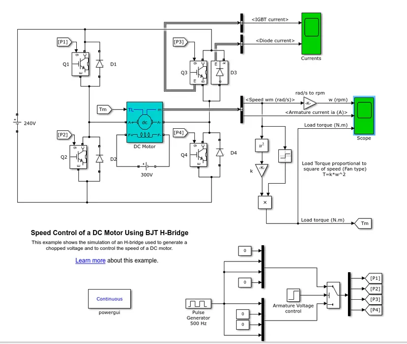
BJT:
Bipolar junction transistor is a device in which the current flow between the two terminals emitter and collector,the base is used to control the current flow of these two terminals.The Bipolar Junction Transistor (BJT) when used for power switching applications, operates as an IGBT.
When it is conducting a forward voltage Vf is developed between collector and emitter (in the range of 1 V). Therefore, the IGBT block can be used to model the BJT device.
The IGBT block does not simulate the gate current controlling the BJT or IGBT.
The switch is controlled by a Simulink® signal (1/0).
The DC motor uses the preset model (5 HP 24V 1750 rpm). It simulates a fan type load (where Load torque is proportional to square of speed). The armature mean voltage can be varied from 0 to 240 V when the duty cycle (specified in the Pulse Generator block) is varied from 0 to 100%.
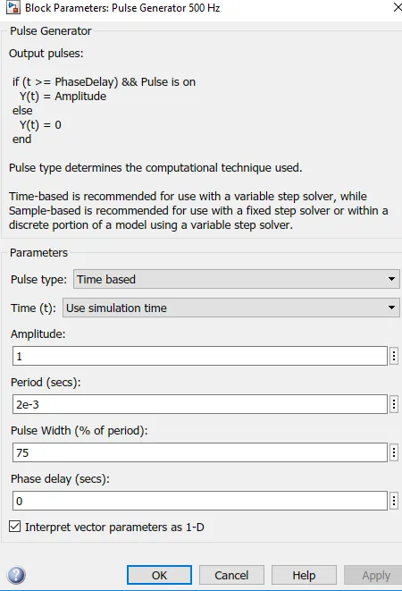
BLOCK PARAMETERS BEFORE MODIFICATION :
SCOPE:
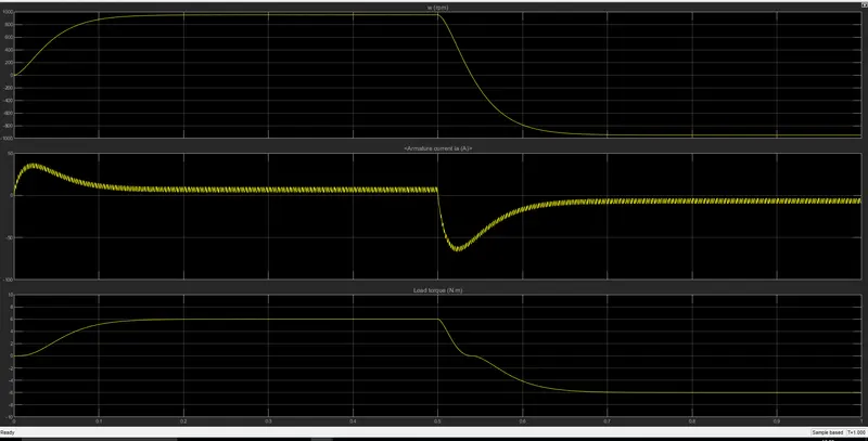
In the above stimulation we can see that the armature current stoop up during the motor changes direction from forward to reverse.
The motor starts in the positive direction with a duty cycle of 75% (mean DC voltage of 180V). At t= 0.5 sec., the armature voltage is suddenly reversed and the motor runs in the negative direction.
Scope shows motor speed, armature current and load torque and 'Currents' shows currents flowing in BJT Q3 and diode D3.
MODIFICATION:
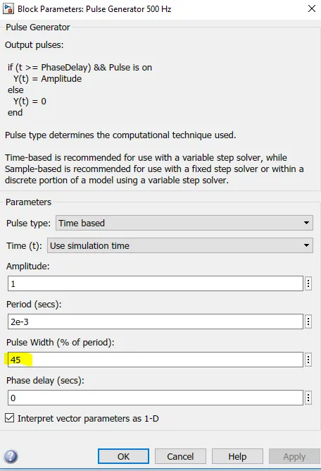
here we have modified the pulse width in order to control the stoop up of the armature current.
RESULT
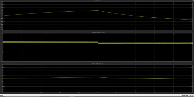
Here the armature current doesn't shoot up when the motor changes its direction from forwarding to reversing.
2.FOUR QUADRANT CHOPPER DC DRIVE:
AIM:
To compare the The Four-Quadrant Chopper DC Drive (DC7) block with H-bridge model.
TYPES OF TRANSISTOR :
1.BJT TRANSISTOR.
2.MOSFET TRANSISTOR
3. IGBT TRANSISTOR
BJT TRANSISTOR:
BJT is the short form of Bipolar Junction Transistor, it is a solid-state current-controlled device which can be used to electronically switch a circuit,Bipolar Transistors are current regulating devices that control the amount of current flowing through them from the Emitter to the Collector terminals in proportion to the amount of biasing voltage applied to their base terminal, thus acting like a current-controlled switch.
MOSFET TRANSISTOR:
A MOSFET is a four-terminal voltage regulating device having source(S), gate (G), drain (D) and body (B) terminals. In general, The body of the MOSFET is in connection with the source terminal thus forming a three-terminal device such as a field-effect transistor. MOSFET is generally considered as a transistor and employed in both the analog and digital circuits.
IGBT TRANSISTOR:
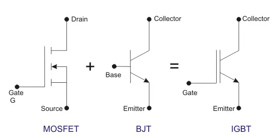
The IGBT is a power switching transistor which combines the advantages of MOSFETs and BJTs for use in power supply and motor control circuits
The IGBT takes the best parts of these two types of common transistors, the high input impedance and high switching speeds of a MOSFET with the low saturation voltage of a bipolar transistor, and combines them together to produce another type of transistor switching device that is capable of handling large collector-emitter currents with virtually zero gate current drive.
The Four-Quadrant Chopper DC Drive (DC7) block:
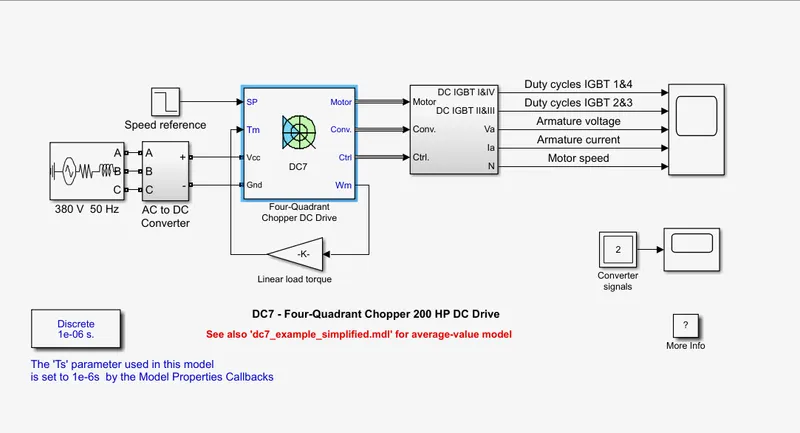
The 200 HP DC motor is separately excited with a constant 150 V DC field voltage source.The armature voltage is provided by an IGBT converter controlled by two PI regulators.
The converter is fed by a 515 V DC bus obtained by rectification of a 380 V AC 50 Hz voltage source.
In order to limit the DC bus voltage during dynamic braking mode, a braking chopper has been added between the diode rectifier and the DC7 block.
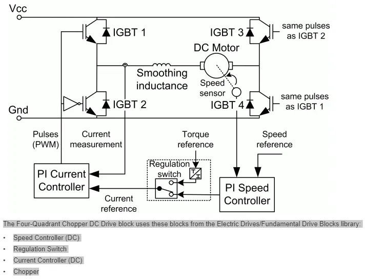
The first regulator is a speed regulator, followed by a current regulator.
The speed regulator outputs the armature current reference used by the current controller in order to obtain the electromagnetic torque needed to reach the desired speed.
The speed reference change rate follows acceleration and deceleration ramps in order to avoid sudden reference changes that could cause armature over-current and destabilize the system.
The current regulator controls the armature current by computing the appropriate duty ratios of the 5 kHz pulses of the four IGBT devices (Pulse Width Modulation).
For proper system behaviour, the instantaneous pulse values of IGBT devices 1 and 4 are opposite to those of IGBT devices 2 and 3. This generates the average armature voltage needed to obtain the desired armature current.
In order to limit the amplitude of the current oscillations, a smoothing inductance is placed in series with the armature circuit.
SCOPE:
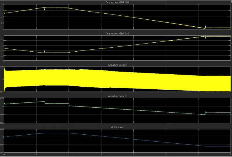
In this simulation we can see that the armature voltage ,armature current,motor speed, duty cycle 1 and 4 is exact opposite to duty cycle 2 and 3
COMPARING THE FOUR QUADRANT CHOPPER DC DRIVE (DC7) BLOCK WITH H BRIDGE MODEL:
The four quadrant chopper offers 4 modes forward motoring, reverse regeneration, reverse motoring, and forward regeneration where as in the H bridge model there are 2 mode forward motoring and reverse motoring.
There is a stoop up in the armature current in H bridge model here there is no stoop up in armature current.
Swithing frequency is higher in four quadrant chopper in comparison with h bridge model.
In the H BRIDGE MODEL the polarity is reversed to change the direction of motor where as in four quadrant chopper speed reference is used to change the direction of the motor.
DC Motor performance is higher in the four quadrant chopper than the h bridge model.
RESULT:
Thus the The Four-Quadrant Chopper DC Drive (DC7) block with H-bridge model is compared.
3.EV MODEL USING DC7 BLOCK:
AIM:
To make a suitable EV model using DC7 block and make result report.
FOUR QUADRANT CHOPPER DC 7 BLOCK:
In a four quadrant dc chopper the 200 HP DC motor is separately excited with a constant 150 V DC field voltage source.The armature voltage is provided by an IGBT converter controlled by two PI regulators.
The converter is fed by a 515 V DC bus obtained by rectification of a 380 V AC 50 Hz voltage source.
EV MODEL :
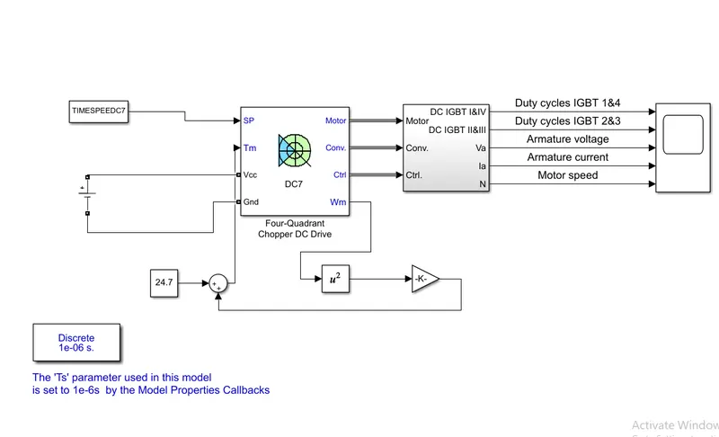
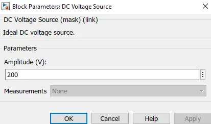
In a electric vehicle there is no need of a convertor as the battery supply dc voltage so we need to remove the Ac power supply and AC to DC converter.Instead of that we will add DC VOLTAGE source.
Then we need to remove an linear load torque block and need to create a sub system for speed torque equation as we know that torque speed equation.
The vehicle speed-torque characteristics is

THE BLOCKS REMOVED:
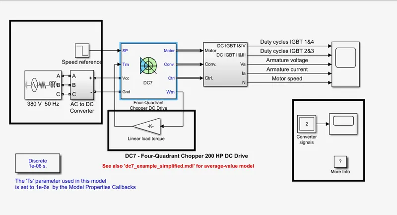
THE BLOCKS ADDED:
1.DC voltage source
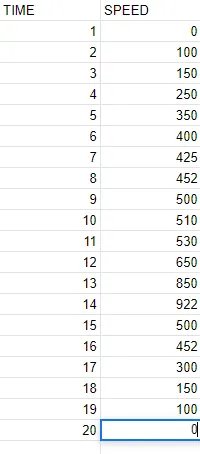
2.From workspace:(the time and speed of an EV given )
3.Math operators according to torque speed characteristics.
SPEED TIME EXCEL SHEET:
EV MODEL USING DC7 BLOCK:
DC VOLTAGE SOURCE:
SIMULATION:
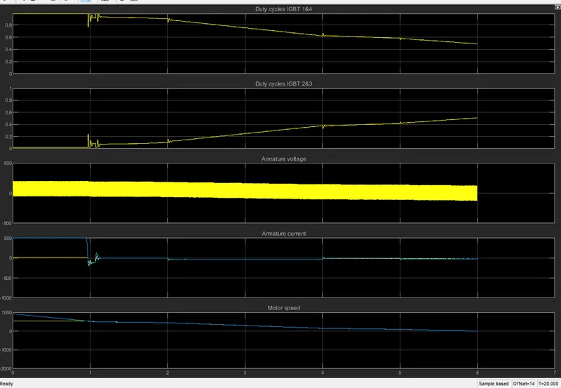
FINAL RESULT:
Thus EV model using dc7 block has been simulated with some required modification and the report has been submitted above.
Here in this DC motor control we have learn about the IGBT,MOFSET,BJT transistors, Speed control of a DC motor using BJT H-bridge and The Four-Quadrant Chopper DC Drive (DC7) block and we have done a EV model using DC7 block.