Week-7 Challenge: DC Motor Control
1. A. Explain a MATLAB demo model named ‘Speed control of a DC motor using BJT H-bridge’.
Objective:
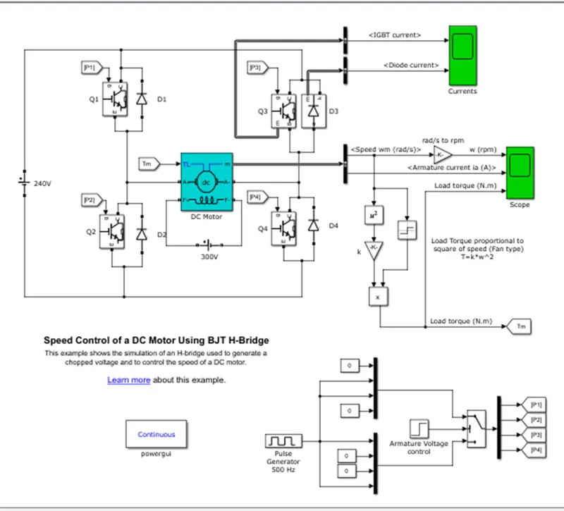
- This is the simulation of an H-bridge which is used to generate a chopped voltage and also to control the DC motor speed.
When BJT is used for power switching applications it operates as IGBT. When it is conducting which means it is operating in saturation region a forward voltage is developed b/w emitter and collector so, IGBT block can be used to model BJT.
The H-bridge consists of four BJT simulated by IGBT models /Diode pairs. Two transistors are switched simultaneously: Q1 and Q4 or Q2 and Q3. When Q2 and Q3 are fired, a negative voltage is applied to the motor, and diodes D1-D4 operate as free-wheeling diodes when Q2 and Q3 are switched off. When Q1 and Q4 are fired, a positive voltage is applied to the motor, and diodes D2-D3 operate as free-wheeling diodes when Q1 and Q4 are switched off
IGBT Current, Diode Current vs Time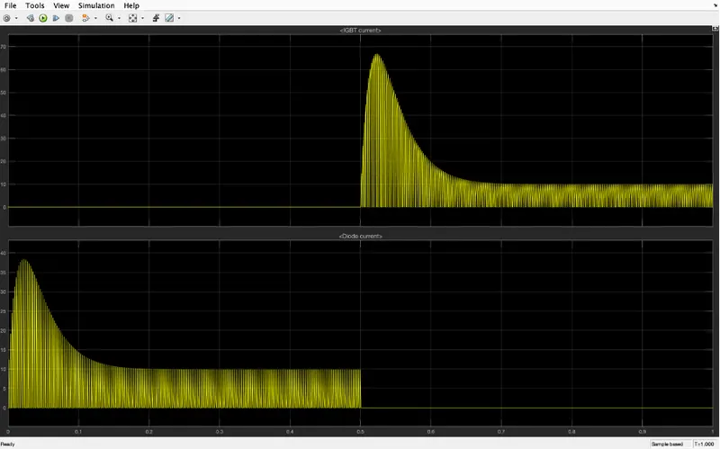
B. Comment on the armature current shoot-up from the scope results.
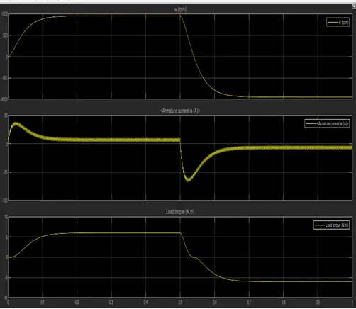
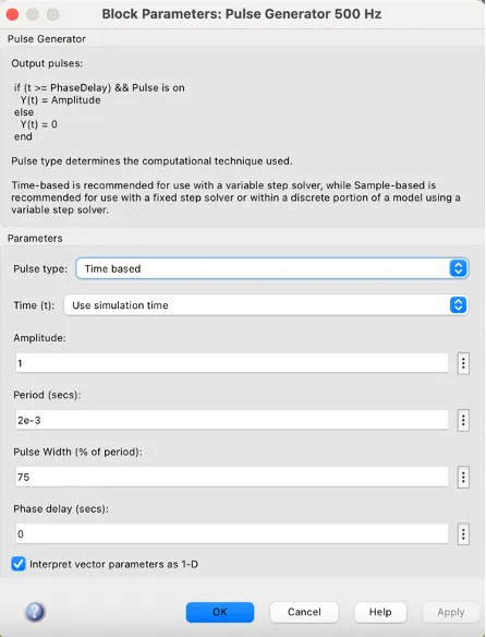
You can see pulse width is 75% which means the program is on for 75% of the time and off for 25% of the time.
We can see that for Q3 and Q4 the input is given after 0.5 seconds so the IGBT signal starts after 0.5 seconds.
Current passes through the diode only during the first half of the cycle.
Pulse width is changed to 50%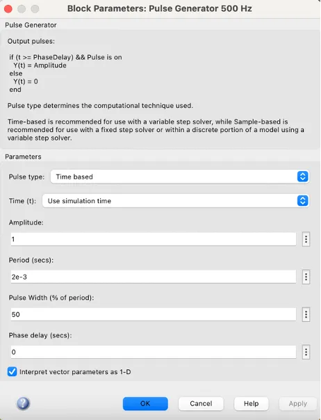
Armature current vs Time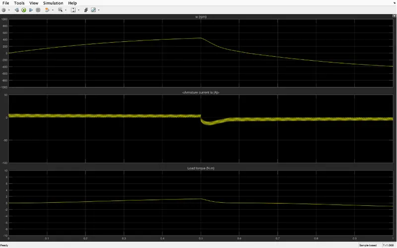
We can observe reducing duty cycle from 75% to 50% armature current changing direction has reduced.
C. Refer to the help section of ‘The Four-Quadrant Chopper DC Drive (DC7) block’. Compare it with the H-bridge model.
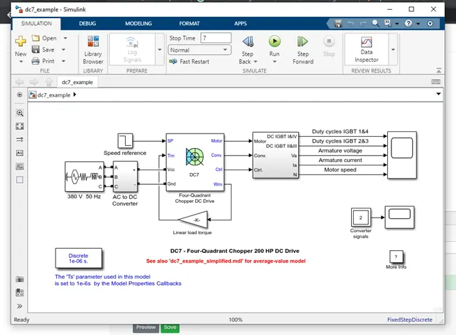
DC7 chopper circuit:
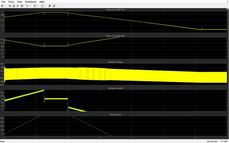
Comparison:
For DC7 - Four-Quadrant Chopper 200 HP DC Drive current for each sector is required and also consists of four-quadrant forward motoring, reverse motoring, forward regenerative braking, and reverse regenerative braking.
H-bridge consists of only forward motoring and reverses motoring.
In DC7 - Four-Quadrant Chopper 200 HP DC Drive to change the direction of rotation of motor the current signal is interrupted with one another.
In BJT to change the direction of rotation of motor polarity of the current is changed.
In DC7 - Four-Quadrant Chopper 200 HP DC Drive PID controller to control and in H-bridge model this is not used.
Circuit diagram for 2-quadrant chopper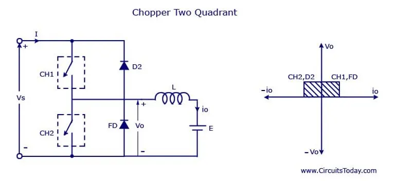
Now we have to make a simulation according to the circuit diagram for a 2-quadrant chopper
Simulation: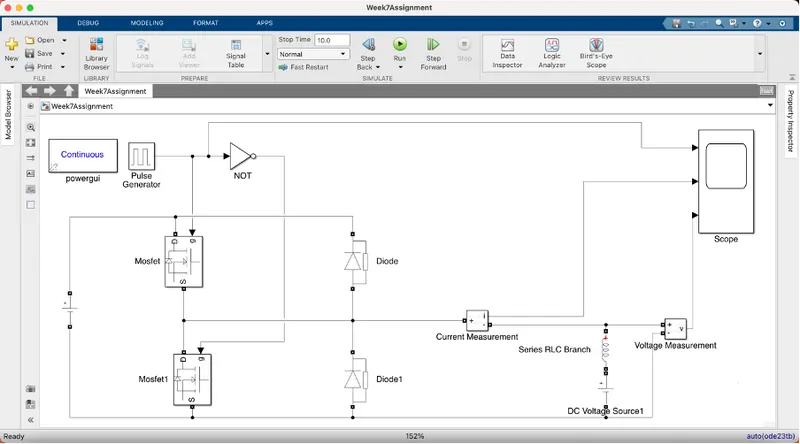
We have used:
- PowerGUI
- Pulse Generator
- DC Voltage Source
- NOT Operator
- Mosfet
- Diode
- Current Measurement
- Series RLC Branch with only inductor
- Voltage Measurement
- Scope
Changing Parameters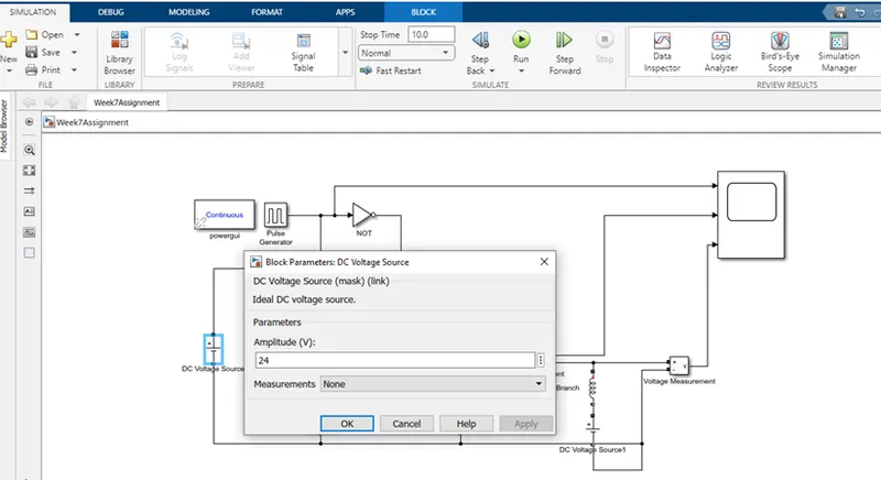
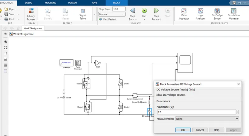
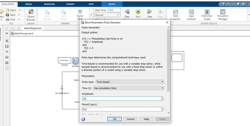
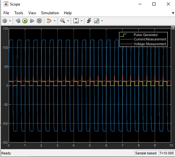
Results from scope: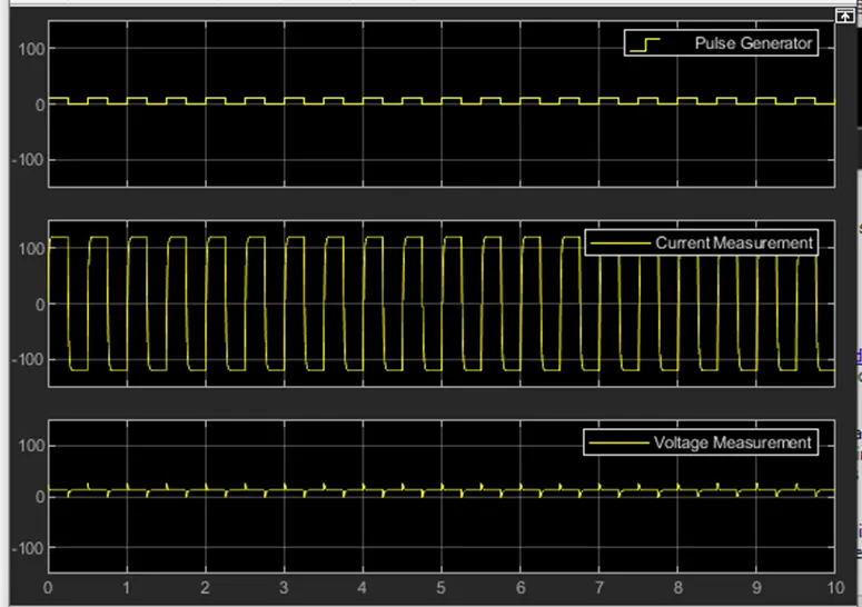
From the result, we can see that voltage is never going to 0 and always lying on positive side of the axis
Current is increasing and decreasing and also lying in both positive and negative axes.
3. Explain in a brief about operation of BLDC motor.
Construction Of A BLDC Motor
A commutator-brushes arrangement helps in achieving unidirectional torque in a typical dc motor. Obviously, commutator and brush arrangement is eliminated in a brushless dc motor. Here, an integrated inverter/switching circuit is used to achieve unidirectional torque. That is why these motors are, sometimes, also referred as 'electronically commutated motors'.
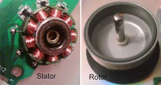
Just like any other electric motor, a BLDC motor also consists of two main parts a stator and a rotor. Permanent magnets are mounted on the rotor of a BLDC motor, and the stator is wound for a specific number of poles. Also, a control circuit is connected to the stator winding. Most of the times, the inverter/control circuit or controller is integrated into the stator assembly. This is the basic constructional difference between a brushless motor and a typical dc motor.
A typical controller provides a three-phase frequency-controlled supply to the stator winding. The supply is controlled by logical control circuits and energizes specific stator poles at a specific point of time. This can be understood from the below animations about working of BLDC motors.
Types Of BLDC Motors
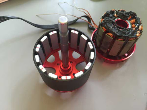
There are two types of BLDC motors based on their construction/design: (i) inner rotor design & (ii) outer rotor design. Regardless of these types, note that the permanent magnets are always mounted on the rotor and winding on the stator.
- Inner rotor design (inrunner): this is a conventional design, where the rotor is located at the core (center) and stator winding surrounds it.
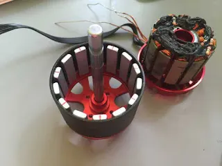
Inner-rotor BLDC motor - Outer rotor design (outrunner): In this configuration, the rotor is external. i.e. stator windings are located at the core while the rotor, carrying permanent magnets, surrounds the stator.
Outer rotor BLDC motor

How Does A BLDC Motor Work?
Stator windings of a BLDC motor are connected to a control circuit (an integrated switching circuit or inverter circuit). The control circuit energizes proper winding at the proper time, in a pattern which rotates around the stator. Permanent magnets on the rotor try to align with the energized electromagnets of the stator, and as soon as it aligns, the next electromagnets are energized. Thus, the rotor keeps running. The animations below will give you a clear idea of 'how a brushless DC motor works?'
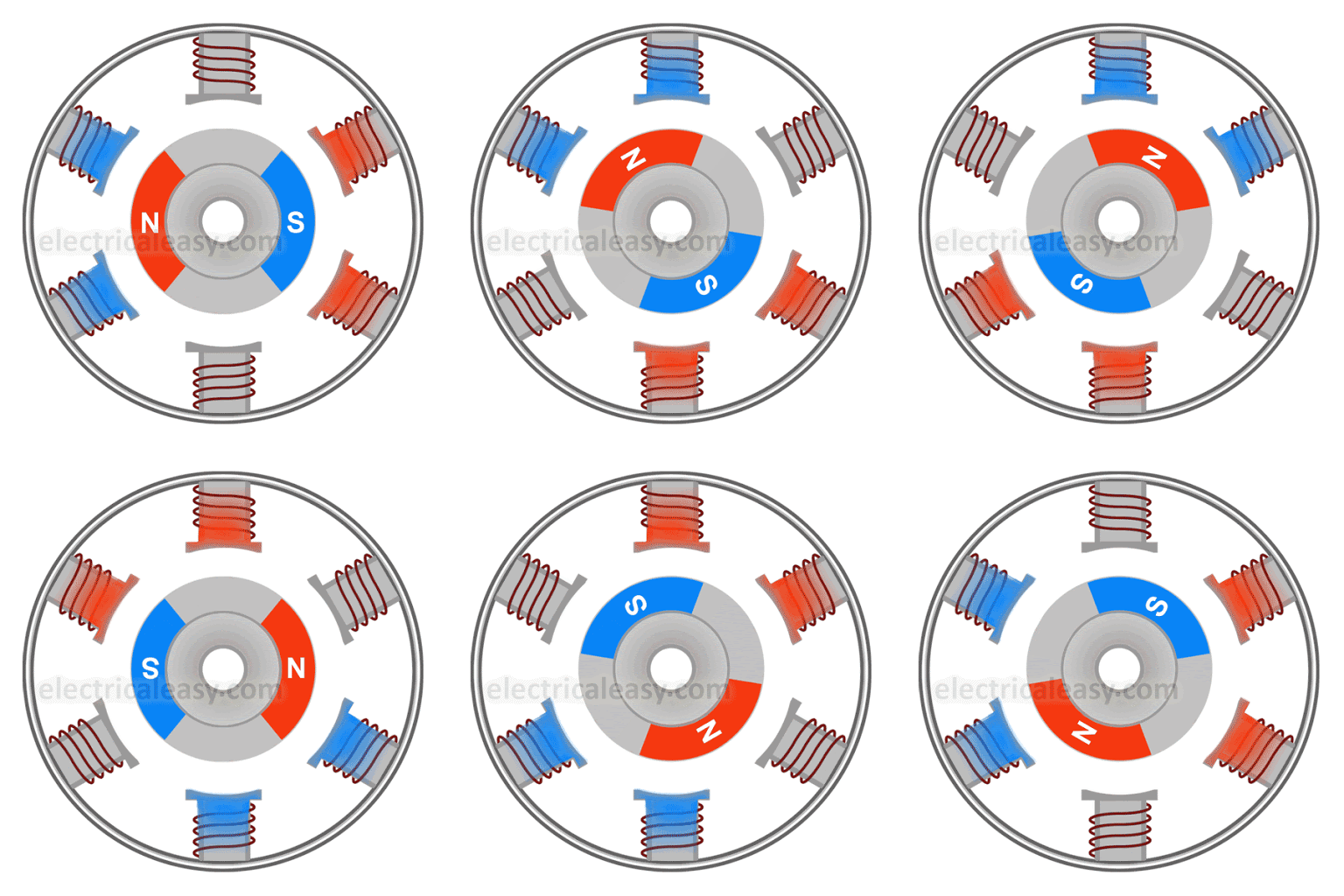 |
Inner rotor BLDC motor working animation |
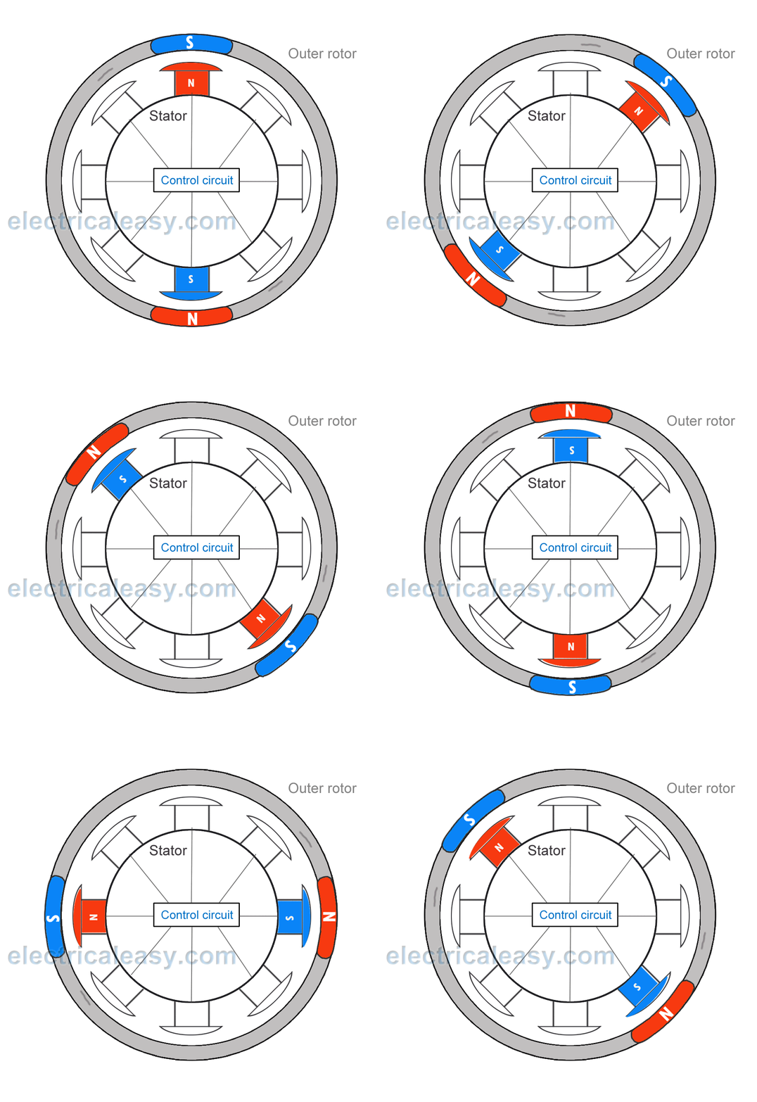 |
| Outer rotor BLDC motor working animation |
Brushless Vs. Brushed DC Motor
- Brushes require frequent replacement due to mechanical wear, hence, a brushed DC motor requires periodic maintenance. Also, as brushes transfer current to the commutator, sparking occurs. Brushes limit the maximum speed and the number of poles the armature can have. These all drawbacks are removed in a brushless DC motor. An electronic control circuit is required in a brushless DC motor for switching stator magnets to keep the motor running. This makes a BLDC motor potentially less rugged.
- Advantages of BLDC motor over brushed motors are increased efficiency, reliability, longer lifetime, no sparking and less noise, more torque per weight, etc.
Applications Of BLDC Motors
BLDC motors fulfill many requirements that a brushed DC motor does. But as they require a complicated control circuit and due to cost considerations, they haven’t yet completely replaced brushed DC motors, especially in low-cost applications. Despite this, there are many applications where BLDC motors dominate –
- Consumer electronics – computer hard drives, small cooling fans, cd/dvd players, etc. and also in modern appliances where quiet operation is desired – such as washing machines, air conditioners, etc.
- Electric Vehicles – many electric vehicles including electric and hybrid cars, electric bikes use BLDC motors.
- They have a wide range of applications in many other areas including robotics, industrial, motion control systems, etc.