Week-7 Challenge: DC Motor Control
1c. The Four-Quadrant Chopper DC Drive (DC7) block
The Dc7-four quadrent chopper 200 HP DC drive model is opened by running the command (dc7_example) using the command window of MATLAB.
The simulation window of the model is given below.
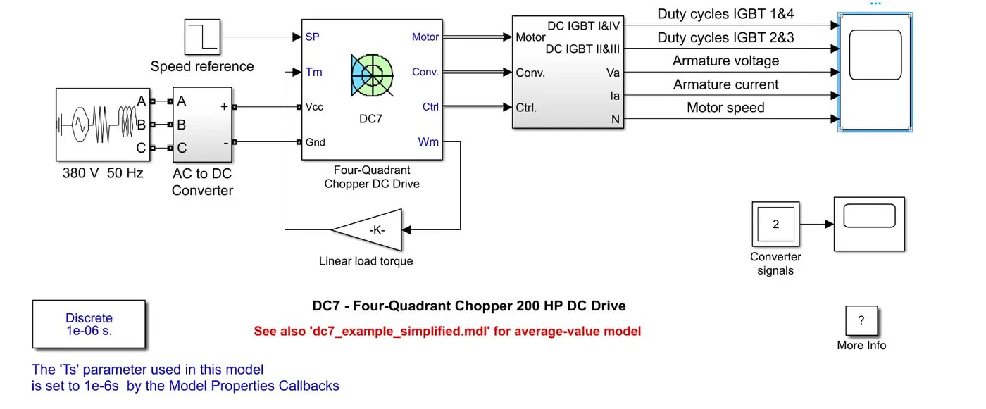
The model consists of a 380V 50Hz three phase AC supply with phase angle 0 which is connected to a converter block. In the converter block it has a rectifier bridge and a braking chopper. The output of the rectfier bridge is connected to the braking chopper. The braking chopper is used to limit the bus voltage during braking mode with a frequency of 4KHz.
A DC7 block situated near the converter block takes inputs such as speed reference, voltage input from AC to DC converter block and load torque value or speed of motor or mechanical rotation port from the motor.
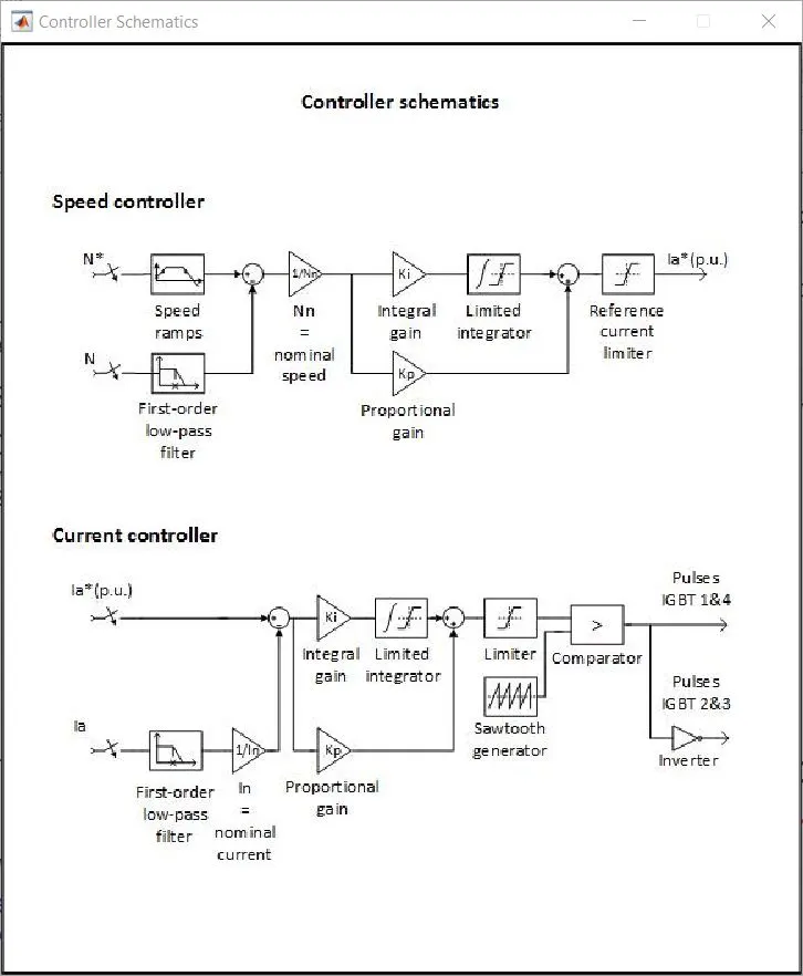
With the above inputs and the standard inputs of the DC machine, controller and converter the outputs are processed in the four quadrent chopper DC drive block. The controller has a schematics by which the speed and current are controlled. The controller schematics are given below.
The Four-Quadrant Chopper DC Drive is given below
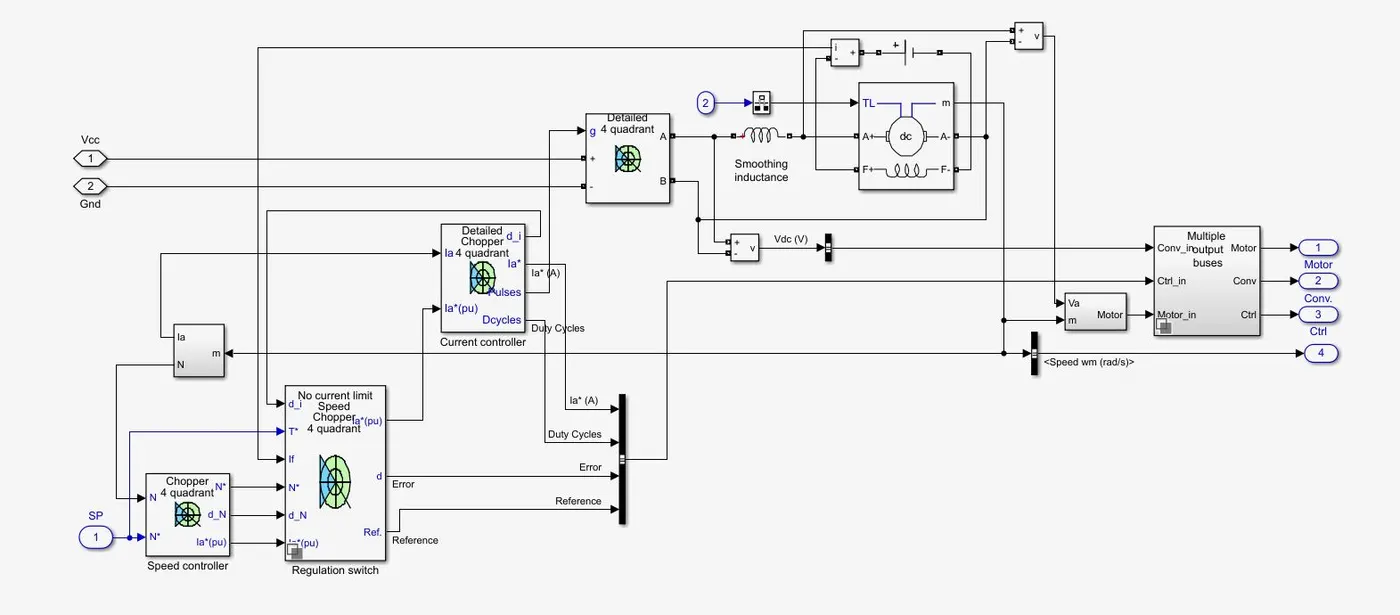
The reference speed is given to the speed regulator and then to the current regulator. The electromagnetic torque required to reach the desired speed is obtained. The IGBT's 1 and 4 are opposite to the IGBT's 2 and 3. They generate the average armature voltage needed to obtain the required armature current. A smoothing inductance is placed in series with the armature current to limit the amplitude of the current oscillation.
Then the signal of motor, controller and converter are given to a subsystem block using a bus operator.
Outputs of armature current, armature voltage and speed are given by the motor and the outputs of current, reference speed, IGBT 1&4 and IGBT 2&3 are given by controller. The converter signal is terminated.
By using the Mux operator the two signals of current from motor and controller are made into one common signal and the speed of the motor and reference speed from motor and controller respectively are made into one common signal.
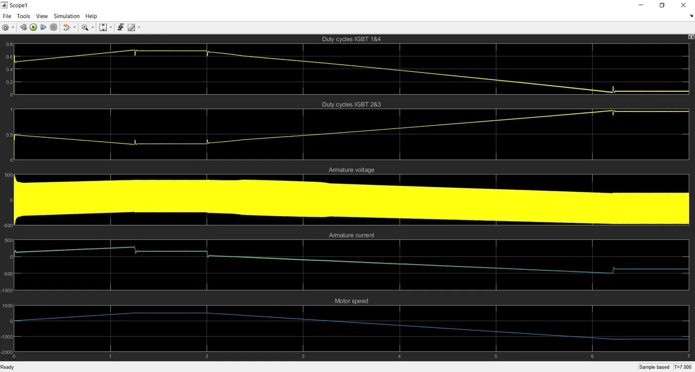
Now, The duty cycle of IGBT 1&4, duty cycle of 2&3, Armature voltage, aramture current and speed are plotted using a scope.
By simulating the model the results plot from the scope is given below.
Comparison of The Four-Quadrant Chopper DC Drive (DC7) block with H-bridge
>The simulation is continuous in H-bridge whereas the simulation is discrete using a four quadrent chopper DC drive.
>Since H-bridge uses continuous simulation the simulation time is less when compared to DC7 block.
>Direction of the motor can be changed by changing the polarity in a H-bridge structured circuit and, the direction of the motor can be changed in a four quadrant chopper DC drive by changing the input signal to the DC7 block.
>Use of snubber in H-bridge circuit is not required but it is required for the DC7 block. This is due to the rapid raise in the voltage when a change in the input signal occurs in the DC7 block.
>Speed of the motor can be varied by variying the duty cycle of the motor in H-bridge circuit. In the DC drive with DC7 block speed of the motor can be varied by the input signal or speed reference.
>Regenerative braking can be done in H-bridge circuit but cannot be done in the four quadrant chopper DC drive.