Week-7 Challenge: DC Motor Control
1 A)
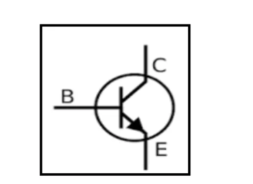
symbol of bipolar junction transistor
BJT
A bipolar junction transistor is a three-terminal semiconductor device which consist of base ,collector and emitter terminals
H bridge
An H-bridge is a simple circuit that lets you control a DC motor to go backward or forward
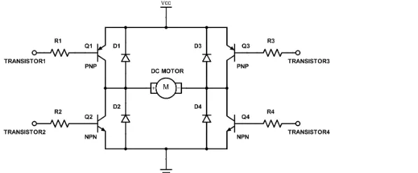
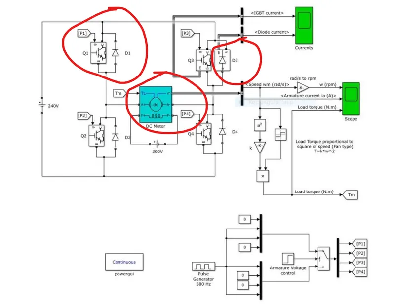
speed contol of a dc motor using BJT H bridge
in this model the IGBT block is used as an BJT device because when it is used for power switching applications.
when it is conducting a forward voltage vf is developed between the collecter and emitter,therefore IGBT block is used
DC motor
in this DC machine block is used as DC motor.
explantion of model
*the speed of the DC motor is controlled by four power electronic switches like IGBT and diode.
*the pulse generater with 75% duty cycle is used to give the input signals to the switches.
*the H bridge consists of four IGBT and diode pairs.
*when the Q1 and Q4 are fired a positive voltage is applied to the motor and diode D2,D3 operates as free wheeling diodes when Q1,Q3 are switched off.
*when Q2,Q3 are operated a negative voltage is applied to the motor and diode D1,D4 operates as free wheeling diodes when Q2,Q3 are switched off.
1 B)The motor starts in the positive direction with a duty cycle of 75% and below are the results
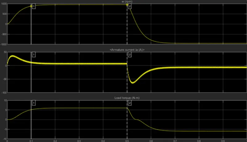
Plot 1 from above shows the Motor Speed against time
Plot 2 shows the Armature Current drawn at each instant
Plot 3 from above figure shows the Load Torque against time
1 C)
below screenshot is model of four quadrant chopper DC drive
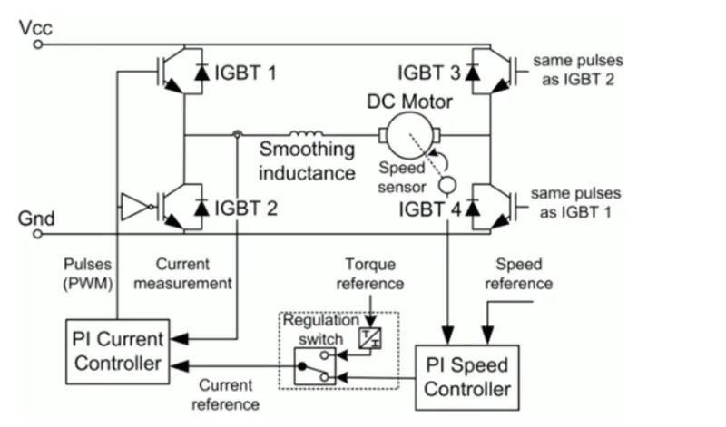
*This block represents a four-quadrant, DC-supplied, chopper (or DC-DC PWM converter) drive for DC motors.
*This drive features closed-loop speed control with four-quadrant operation. The speed control loop outputs the reference armature current of the machine.
*Using a PI current controller, the chopper duty cycle corresponding to the commanded armature current is derived. This duty cycle is then compared with a sawtooth carrier signal to obtain the required PWM signals for the chopper.
*The main advantage of this drive, compared with other DC drives, is that it can operate in all four quadrants (forward motoring, reverse regeneration, reverse motoring, and forward regeneration)
comparison
H bridge
*Only Two quadrants of operation are possible. They are Forward motoring and reverse motoring
*Less complex
*simulation is continuous and simulation time is more
* used in Robotics
Four Quadrnt chopper drive
*It can operate in all four quadrants (forward motoring, reverse regeneration, reverse motoring, and forward regeneration)
*More complex
*discrete and Simulation time is less
*used in automobiles
2) circuit diagram of two quadrant chopper
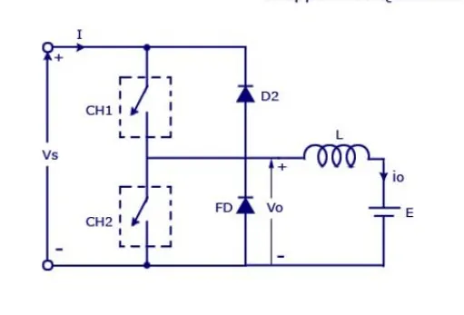
in this type ,the power can either flow from source to load or load to source in this chopper.
*if we connect both these types of chopper in parallel then it is possible to have chopper operation in first as well as second quadrant
*When chopper CH1 is switched ON, source Vs directly gets connected to the load and hence, load voltage Vo is equal to source voltage. The direction of load current is from source to load which is assumed positive.
*When CH1 is switched OFF, the free-wheeling diode FD comes into the circuit as it gets forward biased and hence shorts the load. Therefore, the output voltage Vo becomes zero. However, the io continues to die down through the FD and L in the same direction as shown in circuit diagram. Thus, the average output voltage Vo and current Io are positive and hence operation of chopper is in first quadrant.
*When chopper CH2 is switched ON, load DC source E drives current through CH2 and load. The direction of this current io will be opposite to that shown in circuit diagram and hence is assumed negative. Output voltage Vo is zero during this time. When CH2 is made OFF, diode D2 gets forward biased and hence the current into the source from the load. The output voltage is Vs in this time as the load is connected to the source through D2 during OFF time of chopper CH2. Thus, the load current is always negative i.e. operation of chopper is within second quadrant.
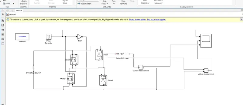
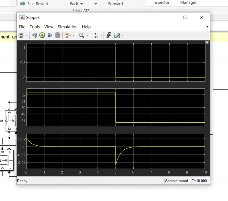
in the above screenshot, we could see clearly that the voltage is always positive but the current becomes both positive and negative.so it can be stated as 2 quadrant chopper
3)
operation of BLDC motor
BLDC motor works on the principle similar to that of a conventional DC motor, i.e., the Lorentz force law which states that whenever a current carrying conductor placed in a magnetic field it experiences a force.
* As a consequence of reaction force, the magnet will experience an equal and opposite force.
* In case BLDC motor, the current carrying conductor is stationary while the permanent magnet moves
*When the stator coils are electrically switched by a supply source, it becomes electromagnet and starts producing the uniform field in the air gap.
*Though the source of supply is DC, switching makes to generate an AC voltage waveform with trapezoidal shape. Due to the force of interaction between electromagnet stator and permanent magnet rotor, the rotor continues to rotate
*With the switching of windings as High and Low signals, corresponding winding energized as North and South poles. The permanent magnet rotor with North and South poles align with stator poles which causes the motor to rotate.
advnantages
*It has no mechanical commutator and associated problems
*High efficiency due to the use of permanent magnet rotor
*less noise while operating because it has no brushes
disadvantages
*These motors are costly
*Electronic controller required control this motor is expensive