Week-7 Challenge: DC Motor Control
OBJECTIVE:
- To run Matlab demo script Speed Control of DC Motor Using BJT H-Bridge and modify the model such that the Armature current doesn't shoot up when the motor changes direction from Forward to Reverse.
- To Compare Four Quadrant Chopper DC Drive (DC7) block with the H-Bridge model.
- To make a suitable EV model using DC7 block.
Procedure:
Power Electronics:
- Power Electronics refers to an interdisciplinary subject within electrical engineering that deals with the design, control, and conversion of power in its electric form.
- A system that converts electric energy to an electric load through a control circuit is known as a Power Electronic System.
- A power electronic Switching device is a combination of active switchable power semiconductor drivers that have been integrated into one.
- The main characteristics of the switch are determined by the internal correlation of functions and interactions of its integrated system.
- Power switching devices are normally selected based on the rating at which they handle power, that is, the product of their current and voltage rating instead of their power dissipation rate.
- Consequently, the major attractive feature in a power electronic switch is its capability to dissipate low or almost no power.
- As a result, the electronic-switch, able to achieve a low and continuous surge of power.
BJT:
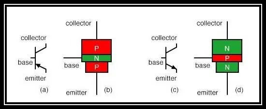
- A Bipolar Junction Transistor BJT is a transistor whose operation depends on the contact made by two semiconductors.
- It can act as a Switch, amplifier, or oscillator.
- Since its operation requires two types of charge carriers "Electrons and Holes", it is known as a Bipolar transistor.
- Holes constitute the dominant charge carrier in P-type semiconductors and in N-type semiconductors the dominant charge carrier is Electrons.
IGBT:
- The insulated gate bipolar transistor IGBT is a semiconductor device with three terminals and is used mainly as an electronic switch.
- It is characterized by fast switching and high efficiency which makes it a necessary component in modern appliances such as lamp ballasts, electric cars, and variable frequency drives VFDs.
- Its ability to turn on and off, rapidly makes it applicable in amplifiers to process complex wave patterns with pulse width modulation.
- IGBT combines the characteristics of MOSFETs and BJTs to attain high current and low saturation voltage capacity.
- It integrates an isolated gate using FET (Field Effect Transistor) to obtain a control input.
- IGBT requires only a small voltage to maintain conduction in the device unlike in BJT.
- The IGBT is a unidirectional device, that is, it can only switch ON in the forward direction.
- This means current flows from the collector to the emitter unlike in MOSFETs, which are bi-directional.
- The IGBT used in medium to ultra high power applications, for example, traction motor.
- In large IGBT, it is possible to handle the high current in the range of hundred amperes and blocking voltages of up to 6KV.
MOSFET:
- Metal Oxide Semiconductor Field Effect Transistor MOSFET is a type of transistor used to switch electronic signals.
- It has four terminals namely: Source S, Drain D, Gate G, and Body B.
- The MOSFET's body is normally connected to the terminal of the Source S, which results in a three-terminal device similar to other field-effect transistors FET.
- Since these two main terminals are usually interconnected via a short circuit, only three terminals are visible in electrical diagrams.
- It is the most common device in circuits that are both digital and analog.
- Compared to the regular transistor, a MOSFET needs a low current of less than one milliampere to switch ON.
- At the same time, it delivers a high current load of more than 50 Amperes.
- MOSFET has a thin layer of silicon dioxide, which acts as the plate of a capacitor.
- The isolation of the controlling gate raises the resistance of the MOSFET to extremely high levels almost infinite.
- MOSFET's exist in two main forms:
- Depletion State- This requires the gate-source voltage (VGB) to switch the component OFF.when the gate is at zero(VGB) the device is usually ON, therefore, it functions as a load resistor for given logic circuits.For loading devices with N-type depletion,3V is the threshold voltage where the device is switched OFF by switching the gate at negative3V.
- Enhancement State-The gate-source voltage (VGB) is required in this state to switch the component ON. When the gate is at zero (VGB) the device is usually OFF and can be switched ON. When the gate is at Zero (VGB) the device is usually OFF and can be switched ON by ensuring the gate Voltage is higher than the source voltage.
Speed Control of DC Motor Using BJT H-Bridge:
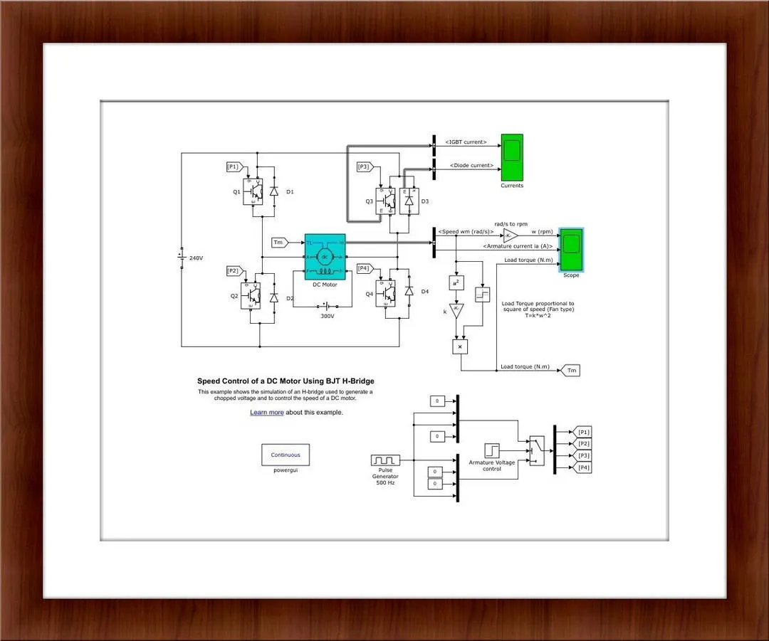
- Using the Matlab Help window, the Speed control of the DC motor using the BJT H-Bridge is opened.
- Link:https://in.mathworks.com/help/physmod/sps/ug/speed-control-of-a-dc-motor-using-bjt-h-bridge.html?searchHighlight=speed%20control%20of%20%20DC%20motor%20BJT%20h%20bridge&s_tid=srchtitle
Description:
- The Bipolar Junction Transistor(BJT) when used for power switching applications, operates as an IGBT.
- When it is conducting (BJT operating in the saturated region), a forward voltage Vf is developed between collector and emitter( in the range of 1V).
- DC motor is connected to the load.
- In the DC motor, the field winding is separately connected to the voltage source of 300V and the armature winding is separately connected to the voltage source of 240V and so this type of DC motor is called Separately excited DC motor.
- The H-Bridge consists of four BJT /Diode pairs.
- Using the pulse generator the switches are excited simultaneously.
- Using the armature voltage control for every 0.5seconds the switch on condition gets reversed.
- When Q1 and Q4 are fired, a positive voltage is applied to the motor, and Diodes D2-D3 operates as free wheeling diodes when Q1 and Q4 are switched off.
- When Q2 and Q3 are fired, a negative voltage is applied to the motor, and Diodes D1-D4 operates as free wheeling diodes when Q2 and Q3 are switched off.
- The motor starts in a positive direction with a duty cycle of 75%.
- At t=0.5 sec, the armature voltage is suddenly reversed and the motor runs in a negative direction.
- The plot obtained as follows:
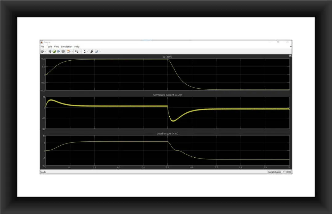
- Due to polarity changes, the direction of rotation of the motor changes, and in that instance the armature current shoot up is very high which can be observed from the second plot.
- This shoot up of current is due to the back emf.
- In order to reduce the back emf, we need to reduce the voltage supply.
- In order to reduce the voltage supply, we need to decrease the ON condition of the switch.
- In order to change that we need to change the duty cycle of the switch.
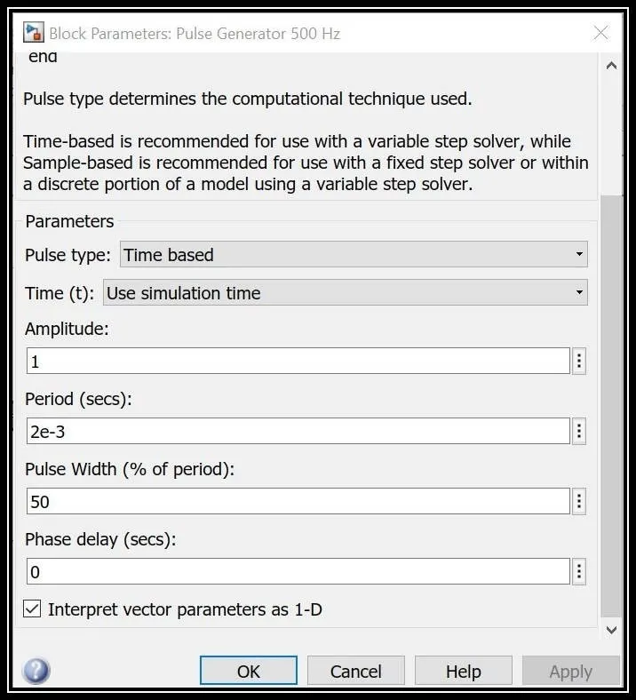
- To change the duty cycle of the switch, we need to alter the width of the amplitude.
- The width of the amplitude is changed to 50% and so the plot obtained is as follows:
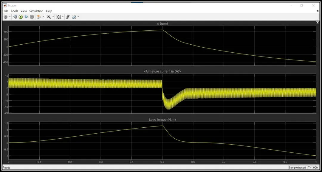
- From the graph, it is evident that the armature current shoot up when the motor changes its direction got reduced from 75A to almost 16A due to changes in the duty cycle of the switch.
2)Comparison between Four Quadrant Chopper DC Drive (DC7) block with the H-Bridge model:
Four Quadrant Chopper DC Drive:
- The Four-Quadrant chopper DC drive (DC7) block represents a four-quadrant, DC supplied, chopper drive for DC motors.
- This drive features closed-loop speed control with the four-quadrant operation.
- The speed control loop outputs the reference armature current of the machine.
- Using a PI current controller, the chopper duty cycle corresponding to the commanded armature current is derived.
- This duty cycle is then compared with a sawtooth carrier signal to obtain the required PWM signals for the chopper.
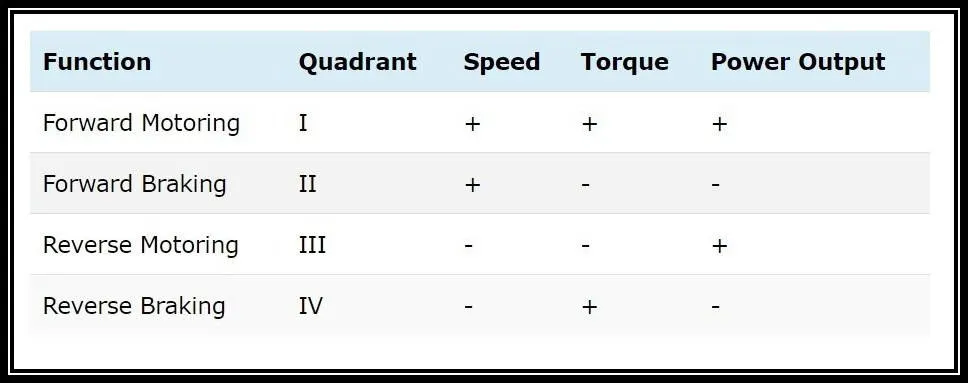
- The main advantage of this drive, compared with other DC drives is that it can operate in all four quadrants (Forward motoring, Forward regeneration, Reverse motoring, Reverse Regeneration).
- In addition due to the use of high switching frequency DC-DC converters, a lower armature current ripple (compared with thyristor-based DC drives ) is obtained.
- However, four switching devices are required, which increases the complexity of the drive system.
- The machine is separately excited with a constant DC field voltage source.
- Thus, there is no field voltage control.
- By default, the field current is set to its steady-state value when a simulation is started.
- The armature voltage is provided by an IGBT converter controlled by two PI regulators.
- The converter is fed by a constant DC voltage source.
- Armature current oscillations are reduced by a smoothing inductance connected in series with the armature circuit.
- The model is discrete.
- Good simulation results have been obtained with a 1`mu`s time step.
- In order to simulate a digital controller device, the control system has two different sampling times:
- The Speed controller sampling time.
- The Current Controller sampling time.
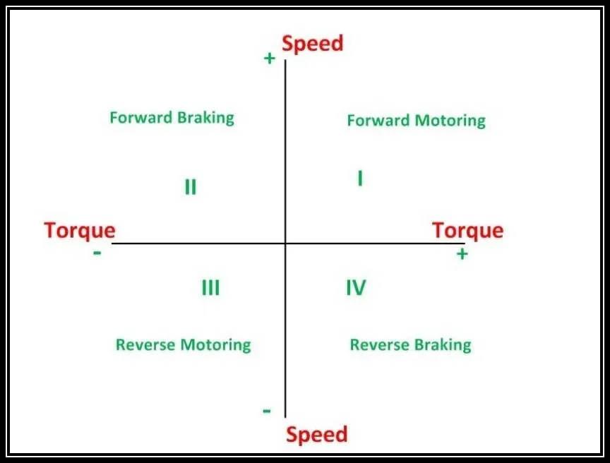
- In the first quadrant, the Power developed is positive and the machine is working as a motor supplying mechanical energy.
- The first quadrant operation is called Forward motoring.
- In the second quadrant, the speed is positive, and the torque is negative, and thus the machine operates as a generator developing a negative torque that opposes the motion.
- The second quadrant operation is called Forward Braking.
- The Kinetic energy of the rotating parts is available as electrical energy which may be supplied back to the mains.
- The third quadrant operation is known as Reverse Motoring.
- The motor works in the reverse direction.
- Since both the Speed and Torque is negative, the power developed is positive.
- In the fourth quadrant, the torque is positive, and the speed is negative.
- This quadrant corresponds to the braking in the Reverse Motoring mode.
Differences between H-Bridge and DC7 block:
- In H-Bridge we need to reverse the polarity of the current in order to change the rotation of the motor whereas in the DC7 block it uses the reference speed to change the direction of rotation.
- Due to the back emf, the current shoot up disturbances are high in H-Bridge.
- The H-Bridge operates only in two modes include Forward motoring and Reverse motoring whereas the DC 7 will work in Four operating conditions includes Forward Motoring, Forward Braking, Reverse Motoring, Reverse Braking.
3)To Build a suitable EV vehicle model using DC7 block:
https://skill-lync.com/knowledgebase/how-to-model-dc7-four-quadrant-chopper-200-hp-dc-drive
- Using the above article, the EV vehicle model is developed using DC7 block.
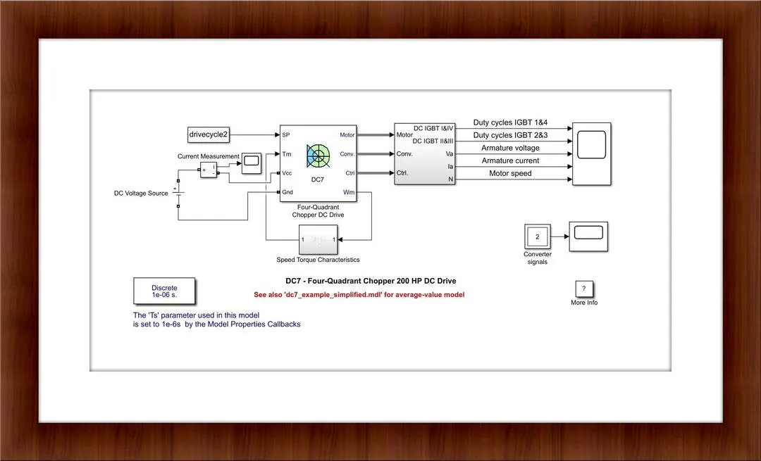
- The EV vehicle model is created using the DC7 block.
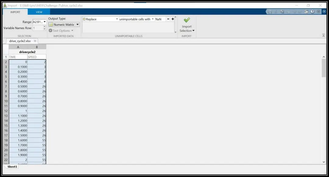
- The input for the drive cycle is imported in the Matlab workspace window and it is used in the Simulink model with the help of from workspace block.
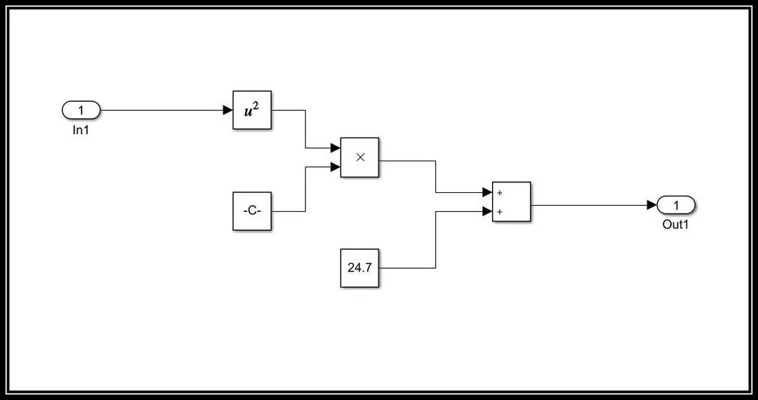
- The Speed Torque characteristics equation block is developed.
Result:
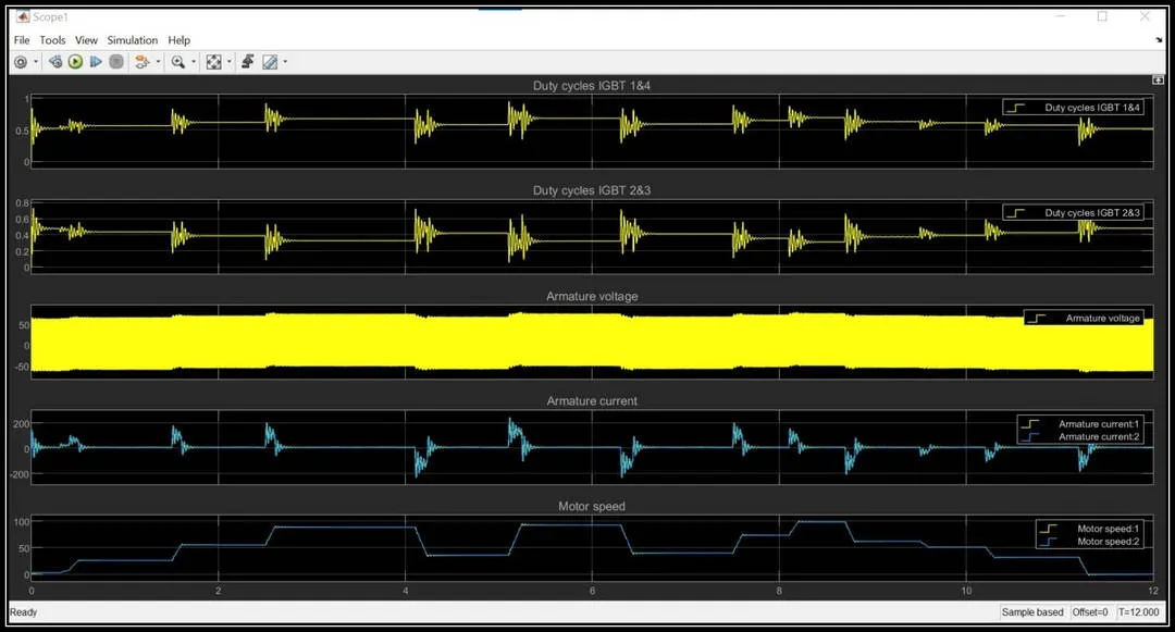
- From the graph, it is clear that the motor speed is in accordance with the input drive cycle.
- The duty cycle of 1&4 increase when motoring conditioning(ie when acceleration) is applied and similarly, the duty cycle of 2&3 gets increased when regenerative braking mode is applied(ie when deceleration occurs)
- The Motor speed decreases whenever there is a decrease in speed and it increases whenever there is an increase in speed.
- The negative armature current indicates that the regenerative mode is activated and so the battery gets charged during this phase.