Week-7 Challenge: DC Motor Control
EV BATCH - 16
Week-7 Challenge: DC Motor Control
Task 1.1:
Explain a MATLAB demo model named ‘Speed control of a DC motor using BJT H-bridge’.
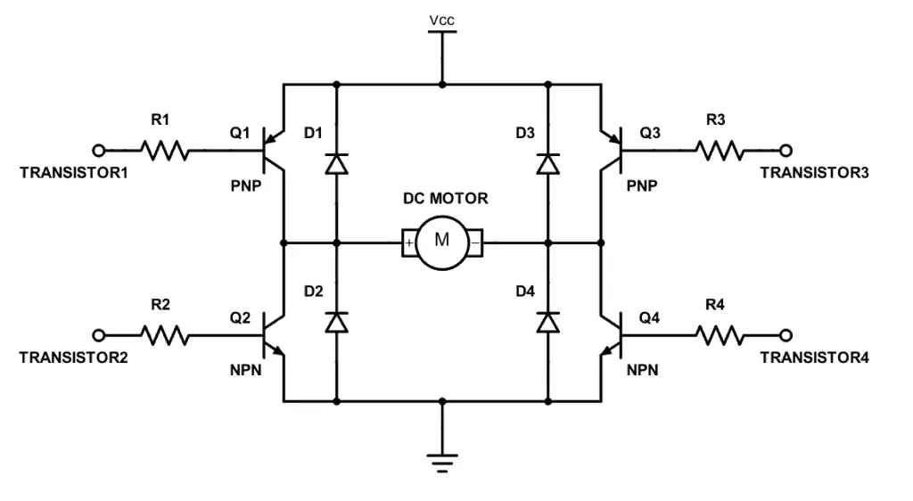
H-Bridge: H-bridge is a rather simple circuit, containing four switching elements, with the load at the center, in an H-like configuration. A BJT H-bridge:
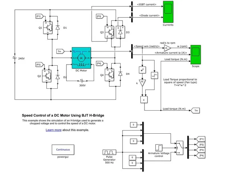
Simulink model of Speed control of a DC motor using BJT H-bridge:
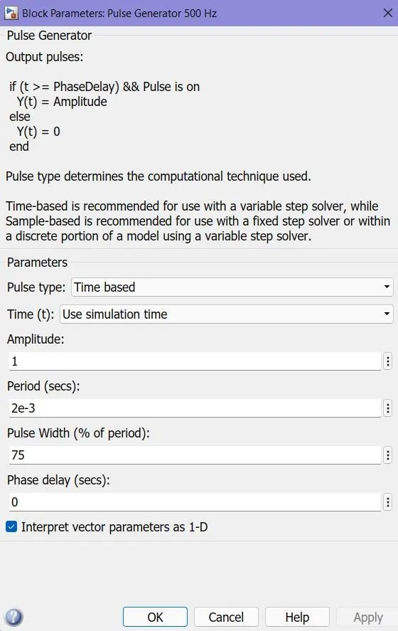
Pulse generator input:
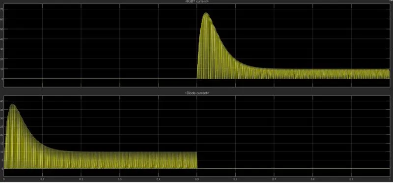
Output plots of IGBT current and Diode current respectively
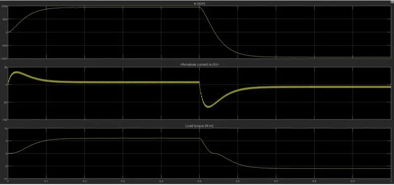
Output plots for w(rpm), Armature current(A), and Load torque(N.m) respectively.
Task 1.2:
Comment on the armature current shoot-up from the scope results.
From the above plot, we can see the armature current shoot up suddenly with the input current but it stables up and reach steady-state in 0.1 seconds. We can also see the rpm also exhibits a similar characteristic as the armature current. It can also be seen that by 0.5 seconds the Q2 and Q3 start operating and the armature current drops and again shoots up and reaches the steady-state.
Task 1.3:
Refer to the help section of ‘The Four-Quadrant Chopper DC Drive (DC7) block’. Compare it with the H-bridge model.
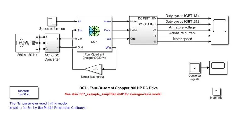
The Four-Quadrant Chopper DC Drive (DC7) block represents a four-quadrant, DC-supplied, chopper (or DC-DC PWM converter) drive for DC motors. This drive features closed-loop speed control with the four-quadrant operation.
The Four-Quadrant Chopper DC Drive block uses these blocks from the Electric Drives/Fundamental Drive Blocks library:
-
Speed Controller (DC)
-
Regulation Switch
-
Current Controller (DC)
-
Chopper
Comparison of DC-7 with H-bridge:
- DC-7 has an AC supply voltage which is converted to DC using a rectifier, H-bridge has a DC supply voltage input.
- In a DC-7 the current supply is distributed across 4-quadrants namely, Forward motoring, forward regenerative braking, Reverse motoring, and reverse regenerative braking. In H-bridge the current is irregularly supplied to each quadrant in fluctuating voltages.
- Regenerative braking is possible only in DC-7 and it is not possible in H-bridge.
- DC-7 is generally used in commercial applications and in electric vehicle battery chargers H-bridge is used.
Task 2:
Develop a 2-quadrant chopper using Simulink & explain the working of the same with the relevant results. (Refer to the article - Multiquadrant operation of the motor )
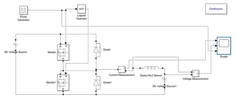
Simulink model:
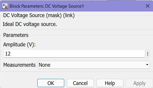
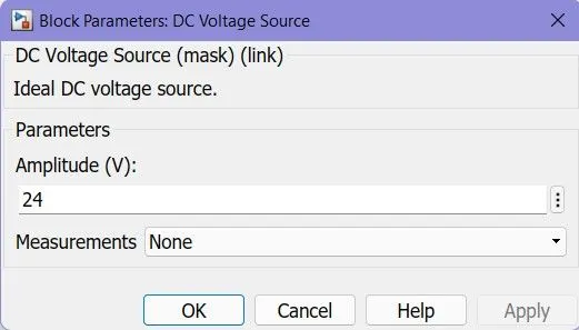
Inputs for voltage sources
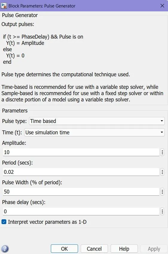
Pulse generator input:
Working:
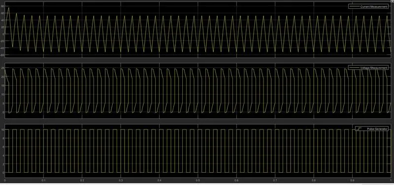
The two-quadrant chopper operates in the first and fourth quadrants, allowing positive and negative output voltage. The Control subsystem implements a simple PI-based control algorithm for controlling the output current. The 2 MOSFETS are connected such as one of them is ON at a time. In the second quadrant chopper, the load must always contain a dc source. When the chopper is on, v 0 is zero but the load voltage E drives the current through the inductor L and the chopper, L stores the energy during the time T on of the chopper.
Result plots:
Task 3:
Explain in a brief the operation of the BLDC motor.
A brushless DC electric motor or BLDC motor, also known as an electronically commutated motor is a synchronous motor using a DC power supply. It uses an electronic controller to switch DC currents to the motor windings producing magnetic fields which effectively rotate in space and which the permanent magnet rotor follows. The controller adjusts the phase and amplitude of the DC current pulses to control the speed and torque of the motor.
Construction:
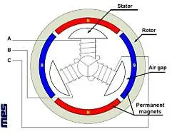
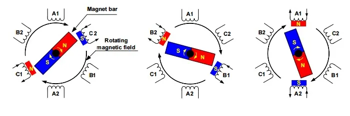
The construction of a brushless motor system is typically similar to a Permanent magnet synchronous motor (PMSM), or an induction motor. They may also use neodymium magnets and be outrunners (the stator is surrounded by the rotor), inrunners (the rotor is surrounded by the stator), or axial (the rotor and stator are flat and parallel).
Working Principle: Lorentz law
Working:
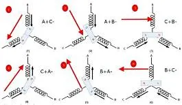
Stator windings of a BLDC motor are connected to a control circuit (an integrated switching circuit). The control circuit energizes proper winding at the proper time, in a pattern that rotates around the stator. The rotor magnet tries to align with the energized electromagnet of the stator, and as soon as it aligns, the next electromagnet is energized. Thus the rotor keeps running. An integrated inverter/switching circuit is used to achieve unidirectional torque.
Advantages and applications:
The advantages of a brushless motor over brushed motors are high power-to-weight ratio, high speed, nearly instantaneous control of speed (rpm) and torque, high efficiency, and low maintenance.
Brushless motors find applications in such places as computer peripherals (disk drives, printers), hand-held power tools, and vehicles ranging from model aircraft to automobiles including electric vehicles.