Week-7 Challenge: DC Motor Control
1. A. Explain a MATLAB demo model named ‘Speed control of a DC motor using BJT H-bridge’.
- what is H-bridge?
An H-bridge is a simple electronic circuit that provide you to control the DC Motor to run backward and forward.
we normally usd it micro controller such as an Arduino, to control motors.
- H- bridge concept-
Here’s the concept of the H-bridge:
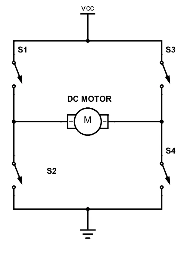
A DC motor spins either backward or forward, depending on how you connect the plus and the minus.
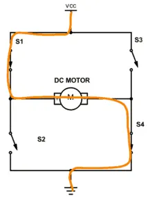
If you close switch 1 and 4, you have plus connected to the left side of the motor and minus to the other side. And the motor will start spinning in one direction.
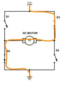
If you instead close switch 2 and 3, you have plus connected to the right side and minus to the left side. And the motor spins in the opposite direction.
Bridge transistor Motor driver
we use the four transistors to connected into the H-bridge circuit.
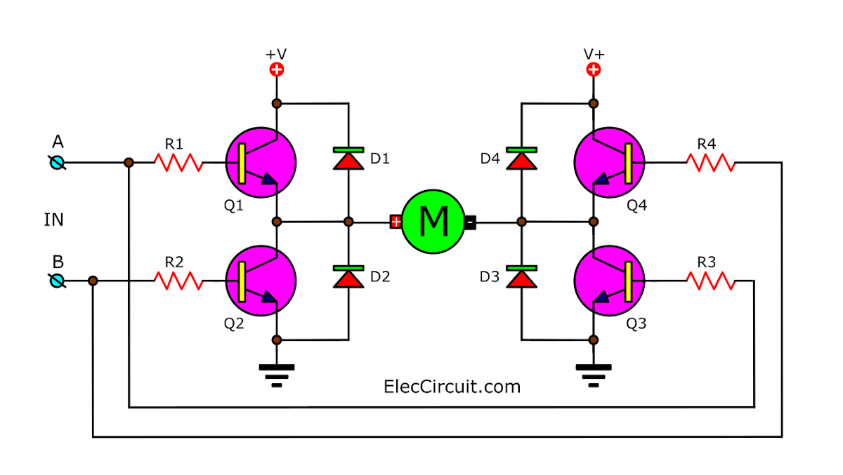
And add a diode to protect the electricity that may flow backward from the motor. Making damage to the transistor.
Explaination of the Model-
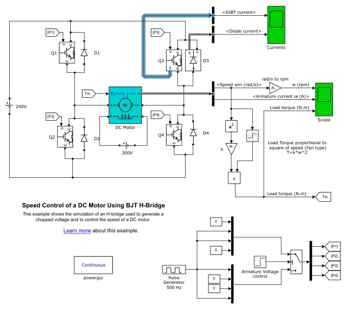
Description
The Bipolar Junction Transistor (BJT) when used for power switching applications, operates as an IGBT. When it is conducting (BJT operating in the saturated region), a forward voltage Vf is developed between collector and emitter (in the range of 1 V). Therefore, the IGBT block can be used to model the BJT device.
The IGBT block does not simulate the gate current controlling the BJT or IGBT. The switch is controlled by a Simulink® signal (1/0). The DC motor uses the preset model (5 HP 24V 1750 rpm). It simulates a fan type load (where Load torque is proportional to square of speed). The armature mean voltage can be varied from 0 to 240 V when the duty cycle (specified in the Pulse Generator block) is varied from 0 to 100%.
The H-bridge consists of four BJT/Diode pairs (BJT simulated by IGBT models). Two transistors are switched simultaneously: Q1 and Q4 or Q2 and Q3. When Q1 and Q4 are fired, a positive voltage is applied to the motor and diodes D2-D3 operate as free-wheeling diodes when Q1 and Q4 are switched off. When Q2 and Q3 are fired, a negative voltage is applied to the motor and diodes D1-D4 operate as free-wheeling diodes when Q2 and Q3 are switched off.
Simulation
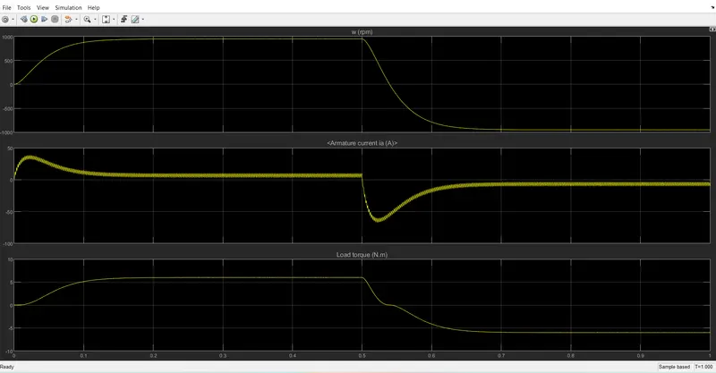
The motor starts in the positive direction with a duty cycle of 75% (mean DC voltage of 180V). At t= 0.5 sec., the armature voltage is suddenly reversed and the motor runs in the negative direction.
'Scope' shows motor speed, armature current and load torque and 'Currents' shows currents flowing in BJT Q3 and diode D3
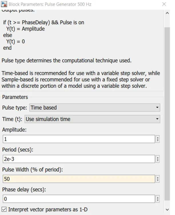
The Pulse generator given by a pulse width of 75% and period of 2e-3 seconds . the motor parameters of the torque and the field voltagge and armature voltages are taken as defaults values of the model.
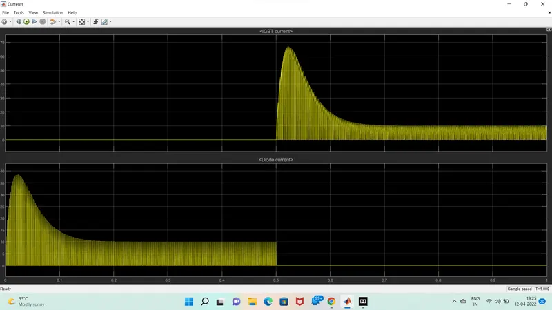
from output i notice that the from 0 to 0.5 time period the igbt current is 0 and the diode current is on, after the 0.5 to 1 time period the igbt stsrts the currents flow the diode current is 0
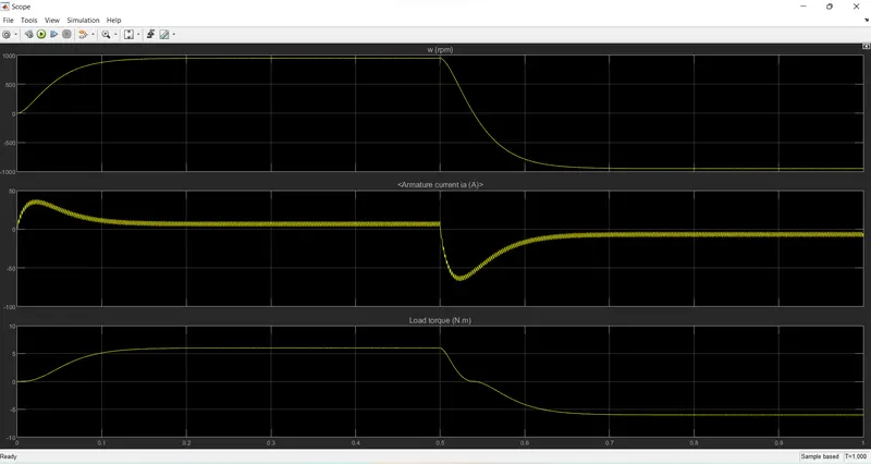
the speed is start increasing gradually from 0 to maximum speed (1000rpm) and after 0.5 sec its start decreasing and reach to negative max(-1000rpm).
The armature start increase form 0 to max45 and then decrease suddenly and reach near to the 0 value .
when the speed decrease then the armature current is also start flowing in reverse direction , when speed comes to the near -1000rpm the armature current is flow in negative direction near to 0 value .
at starting their is suddden spike in current flow and also in the negative direction of current.
B. Comment on the armature current shoot-up from the scope results.
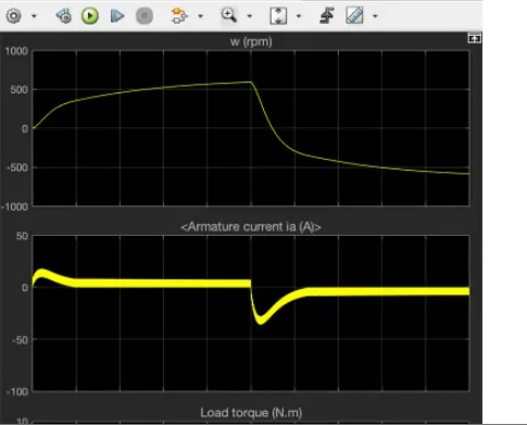
I observe that when we reduced the duty cycle then there will be slight reduction of armature current. now i shows u how armature current reduced according duty cycle-
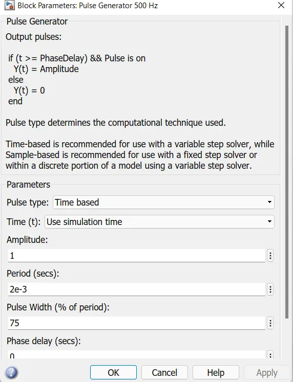
for 50% duty cycle
C. Refer to the help section of ‘The Four-Quadrant Chopper DC Drive (DC7) block’. Compare it with the H-bridge model.
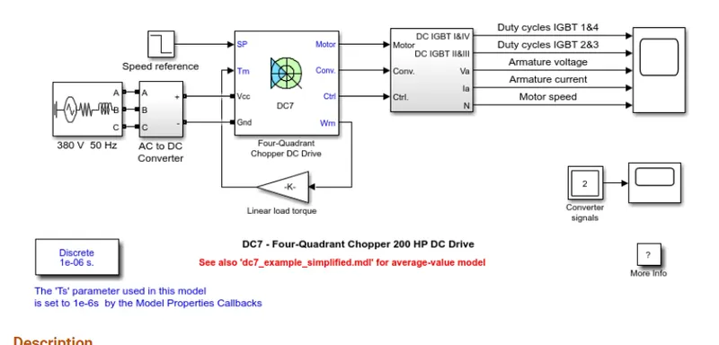
The 200 HP DC motor is separately excited with a constant 150 V DC field voltage source. The armature voltage is provided by an IGBT converter controlled by two PI regulators. The converter is fed by a 515 V DC bus obtained by rectification of a 380 V AC 50 Hz voltage source. In order to limit the DC bus voltage during dynamic braking mode, a braking chopper has been added between the diode rectifier and the DC7 block.
The first regulator is a speed regulator, followed by a current regulator. The speed regulator outputs the armature current reference (in p.u.) used by the current controller in order to obtain the electromagnetic torque needed to reach the desired speed. The speed reference change rate follows acceleration and deceleration ramps in order to avoid sudden reference changes that could cause armature over-current and destabilize the system. The current regulator controls the armature current by computing the appropriate duty ratios of the 5 kHz pulses of the four IGBT devices (Pulse Width Modulation). For proper system behaviour, the instantaneous pulse values of IGBT devices 1 and 4 are opposite to those of IGBT devices 2 and 3. This generates the average armature voltage needed to obtain the desired armature current. In order to limit the amplitude of the current oscillations, a smoothing inductance is placed in series with the armature circuit.
Simulation
Before starting the simulation, set the initial bus voltage to 515 V via the GUI block ('Initial States Setting' button and 'Cbus' variable).
Start the simulation. You can observe the motor armature voltage and current, the four IGBT pulses and the motor speed on the scope. The current and speed references are also shown.
The motor is coupled to a linear load, which means that the mechanical torque of the load is proportional to the speed.
The speed reference is set at 500 rpm at t = 0 s. Observe that the motor speed follows the reference ramp accurately (+400 rpm/s) and reaches steady state around t = 1.3 s.
The armature current follows the current reference very well, with fast response time and small ripples. Notice that the current ripple frequency is 5 kHz.
At t = 2 s, speed reference drops to -1184 rpm. The current reference decreases to reduce the electromagnetic torque and causes the motor to decelerate with the help of the load torque.
At t = 2.2 s, the current reverses in order to produce a braking electromagnetic torque (dynamic braking mode). This causes the DC bus voltage to increase.
At t = 3.25 s, the motor reaches 0 rpm and the load torque reverses and becomes negative. The negative current now produces an accelerating electromagnetic torque to allow the motor to follow the negative speed ramp (-400 rpm/s). At t = 6.3 s, the speed reaches -1184 rpm and stabilizes around its reference.
The difference between the four quadrant chopper and the H-bridge is-
- In four- quadrant chopper the motor can be operated in all the four modes( forward motoring, reverse motoring , forwaerd braking and reverse braking ) but in H-bridge model we have only two modes forward and reverse by changing the direction of motor.
- in chopper the vehicle control is better but in H-bridge the vechile control is less.
- regenerative braking can be achived in four quadrant chopper but in H-bridge regenerative braking is not possible.
2. Develop a 2-quadrant chopper using simulink & explain the working of the same with the relevant results. (Refer to article - Multiquadrant operation of motor )
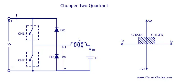
to create model of two quadrant chopper we used pulse generator, dc source, mosfet, diode, logic operator, scope , powergui,voltage and current measurment block and series rlc branch.and connect in this fashion given below.
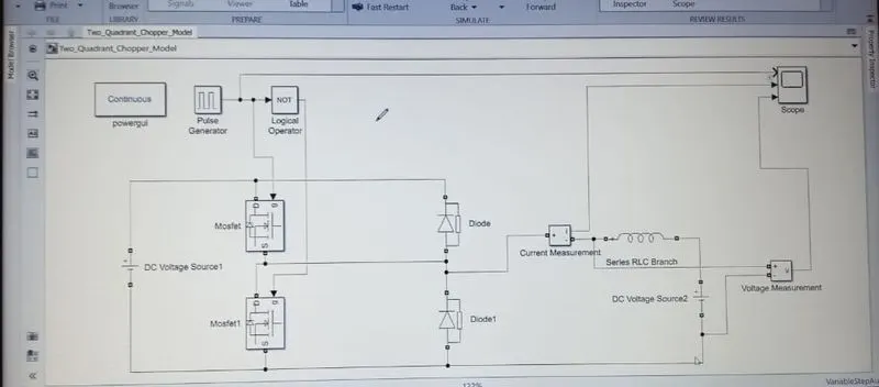
now we run the model and get output.
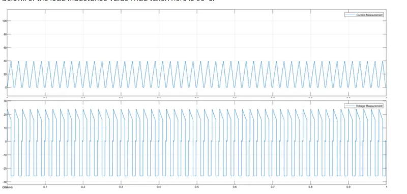
The output of the current waveform is positive direction and the voltage waveform is in positive and the negative half cycle
thus is the two quadrant operation of a chopper type- D the current is positive and the voltage can be positive and negative -

3. Explain in a brief about operation of BLDC motor.
what is BLDC motor ?
The brushless DC motor is a type of direct current (DC) motor that does not use brushes. In a conventional brushed motor, a brush and commutator assembly conveys current to the coil windings. A brushless motor lacks these parts. Instead, it employs semiconductor switches to serve the same purpose.
Because it use electronic switches, a brushless motor is also called an electronically commutated motor (ECM)- or simply EC motor. Other names that the motor goes by are BLDC motor and BL motor. BL stands for brushless, and denotes the device’s construction and operation.
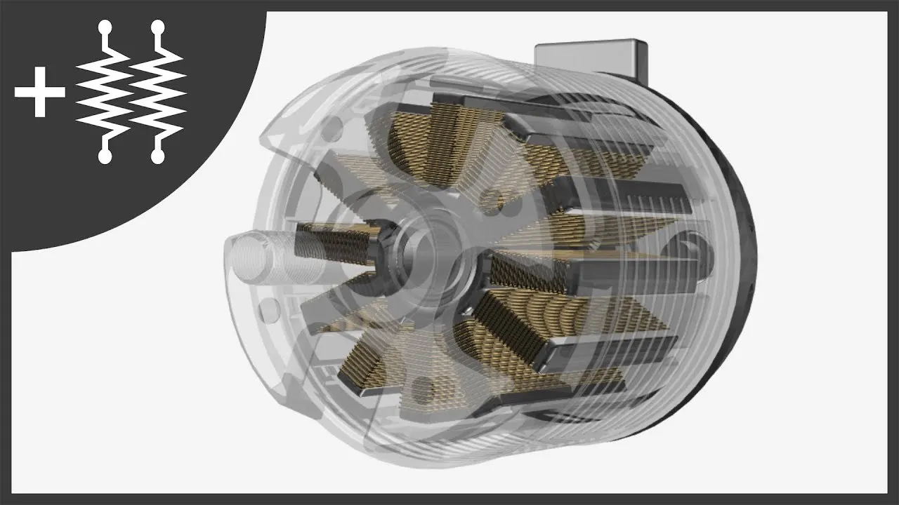
Construction of BLDC motor-
The brushless DC motor design is almost similar to that of the brushed type, save for a few components. It contains both rotor and stator, for example, which primarily consist of permanent magnets and electromagnets respectively. Additional parts that are specific to BL motors include sensors and the electronic controller. In a nutshell, the main brushless DC motor components are:
- Stator
- Rotor
- Position Sensors
- Electronic Controller
The parts, their images, and functions are discussed in more detail below.
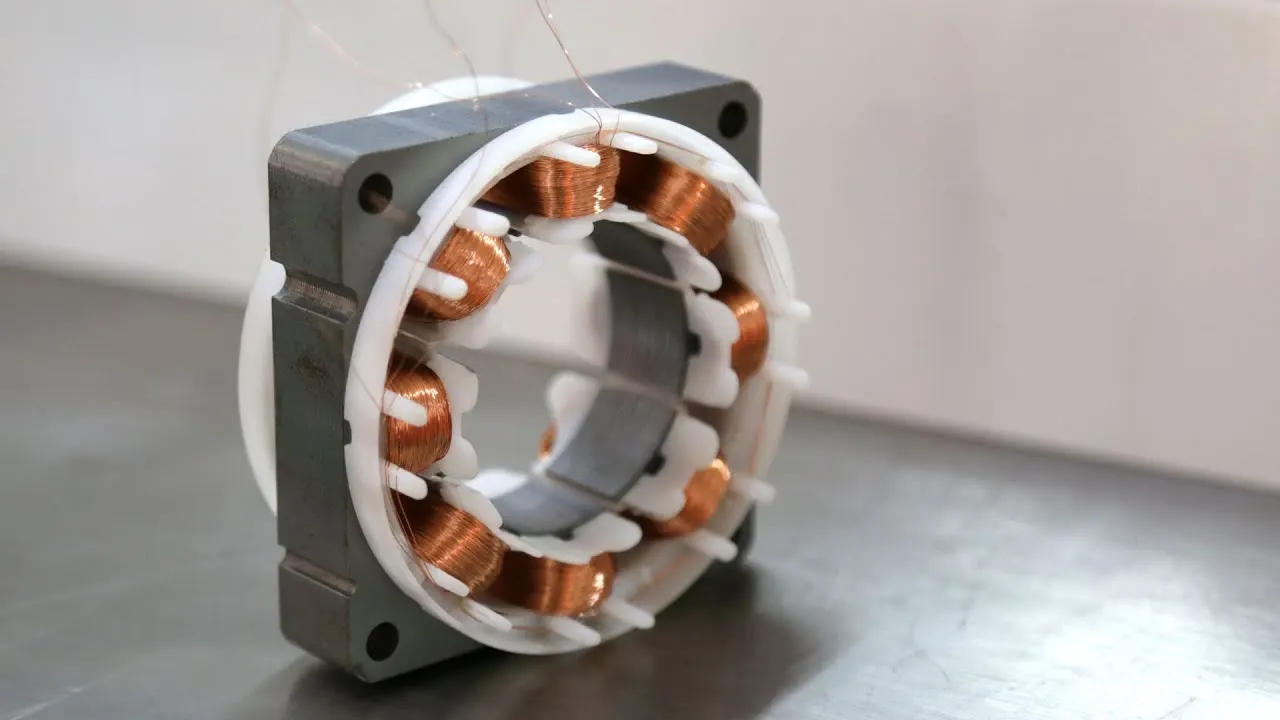
STATOR
The stator is the part that produces a shifting magnetic force to cause the rotor to spin. It’s usually either inside and surrounded by the rotor or outside and enclosing the rotor. The brushless DC motor stator typically consists of laminated steel stampings. These are normally stacked together to form a magnatic core. A coil of wire is then wound around the core (as shown in the image above) and connected to the controller.
The steel pieces of a brushless DC motor stator are usually either slotted or slotless. Slotless cores produce high speed motors due to the low inductance. However, the design increases the cost to manufacture the motor since it requires a higher number coil turns.
The stator is also normally made up of 3 different windings connected using either a star or delta pattern. Due to the coil arrangement, a star pattern produces a higher torque level at lower speeds. A delta pattern, in contrast, produces a low level of torque at low motor rpm.
The coils of a brushless motor are further classified as trapezoidal and sinusoidal types based on the type of operating signal or back EMF . A trapezoidal brushless DC motor stator has the drive current and back electromotive force (EMF) assume trapezoid shapes. The Sinusoidal motor, on the other hand, has the signal forming a sine wave.
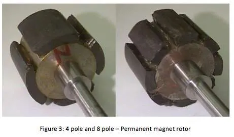
ROTOR
The rotor in a BLDC motor is a permanent magnet. It provides the magnetic field that reacts with that of the stator and enables a rotational motion. Different materials are used for this part. The most common rae earth materials such as Ferrite, Neodymium, alloy of Neodymium, Boron, and Samarium Cobalt.
Just like the stator, the rotor of a BL motor may be on the outside (in an in-runner motor) or inside (in an out-runner motor). Each configuration has its up and downsides, including the ability to produce compact motors, rotor momentum, and more.
The number of poles in a brushless DC motor rotor mostlly varies from 2 to 8. These are normally arranged sequentially, with opposite poles bordering one another. The placement of the magnets also differs based on application. They may be placed on the rotor outer surface, embedded, or inserted into the core.
It’s good to mention how the number of magnets or poles on the rotor affects the working characteristics of brushless DC motor assemblies. Having more poles increases the motor’s torque. However, it decreases the speed and smoothness of operation. The magnet material also has an impact on the motor, with high ferrite materials increasing torque.
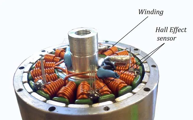
Position Sensors
As earlier indicated, a BLDC motor is electronically commutated. For that to happen, the motor’s controller must know the position of the rotor at any time. Doing so allows it to switch power to the right electromagnet and at the right time. Most BL motors, therefore, incorporate position sensors. A brushless DC motor sensor is usually the Hall effect type , a resolver, or optical encoder.
Each type of sensor offers benefits and drawbacks when used in specific situation. An optical sensor gets affected by dirt easily, for instance, and does not fit applications that are too dusty. Resolvers are, on the other hand, robust and great for harsh environments. Hall sensors provide for low-cost brushless DC motor components, but are affected by high heat and vibrations.
A majority of BL motors use Hall sensors. These work by generating voltage from a magnetic field. The voltage is then used to determine the field’s intensity. A Hall sensor’s output is ether high or low depending on the type of pole (North or South) that has passed near it.
A sensored motor relies on sensor data to calculate the position of the magnets on the rotor as well as the pole orientation. That way, its controller automatically commutates the stator coils. The brushless DC motor hall sensor is usually placed in the stator coils, although sensor positions vary by type of motor.
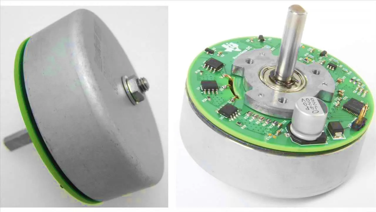
Electronic Controller
This is the brushless DC motor commutator. Its function is to switch on the motor’s stator windings in turns, thereby allowing the permanent magnet rotor to spin. The controller also regulates various aspects of the motor operation, such as torque and speed.
There are different types of controllers used with BLDC motors. These are generally classified as sensored and sensorless controllers. A sensored controller operates a motor that uses sensors, a sensorless controller the type motors that uses no sensors.
A brushless DC motor controller circuit can be a microcontroller or digital signal processor. It can also be a dedicated IC that integrates all the control features. It’s one of the most important parts, though, when it comes to the operation of brushless motors.
Other Parts
Minor components of a BLDC motor, but which are important parts of the construction, include the following.
- Bearing– this part supports the shaft at either end of the motor assembly and allows its smooth rotation
- Shaft– a metal rod that holds the rotor and rests on the motor’s housing. It projects on one end of the motor to transmit motion
- Casing– this is the housing that protects the parts of the motor assembly. Usually made from a lightweight material such as aluminum
How a Brushless DC Motor Works
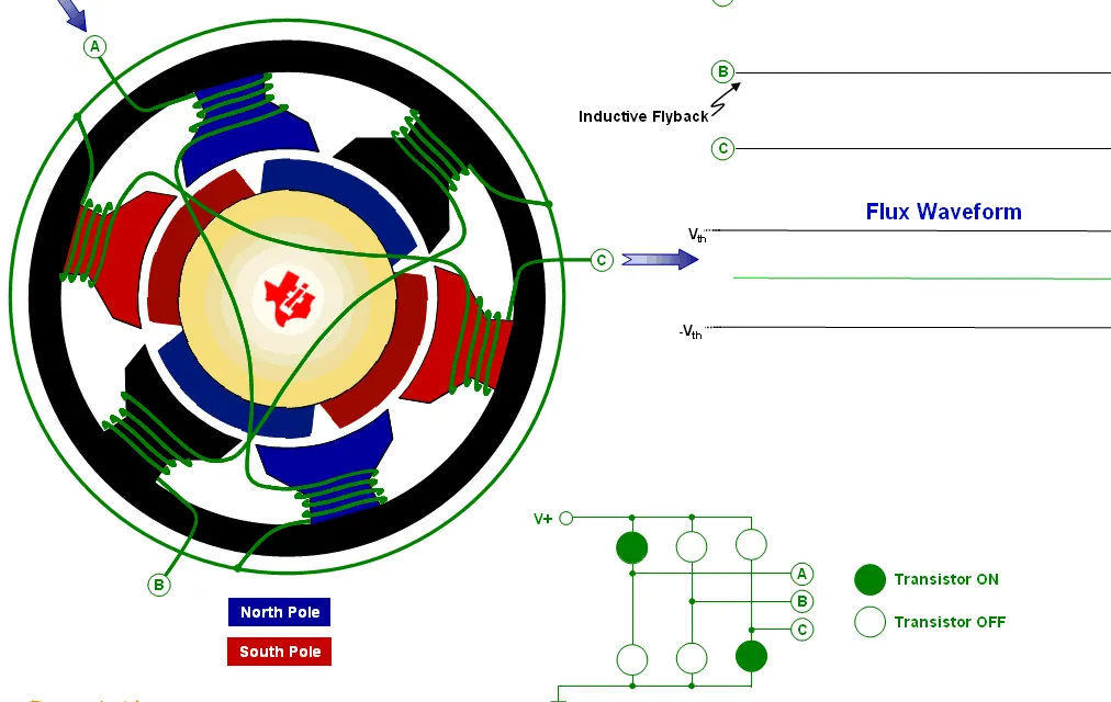
The brushless DC motor working principle is more complex than that of a brushed motor and uses more electronic components. To help you understand its operation, I will use the parts that you have just learned about such as stator, coil windings, and rotor assembly. Here is the working of a Brushless DC motor explained.
- A BLDC motor primarily consists of a rotor (rotating part) and stator (stationary part). The stator is usually a series of electromagnets made of magnetic cores around which are wound wire coils. The rotor on the other hand, is composed of several permanent magnets arranged end to end, with opposite poles facing each other.
- When current flows through the coil of a brushless motor, a magnetic field is generated . The magnetic field reacts with that of the rotor’s permanent magnet next to it, producing either an attraction or repulsive force. In a typical brushless DC motor operation, two coils are energized at the same time. One coil attracts a part of the rotor, while the other repulses it. This causes the rotor to move.
- For continuous motion, the next coil must energize, while the previous coil loses magnetism. The magnetic field then literary rotates around the stator, while the rotor practically chases it. This causes a continuous revolution of the rotating part of the motor.
To ensure smooth rotation and continuity, the magnetic forces must occur on the right coil and at the right time. This is made possible by using an electronic circuit, or what’s called the brushless DC motor controller circuit.
But the circuit must sense the position of the rotor so it can calculate the switching pattern. For that, most BL motors use sensors, which can be magnetic or optical. Most BL motors use Hall sensors, as mentioned earlier. When the rotor moves, the sensor generates a voltage. The magnitude of the voltage depends on whether the nearest pole is North or South.
There are also BLDC motors that do not use sensors to detect rotor position. Instead, they depend on the back EMF or back electromotive force to do that. This is the voltage produced in the stator coils when the motor is in operation.
Brushless DC Motor Speed Control
One of the most important aspects of a BLDC motor is its speed control. This feature is normally implemented by the use of high-tech systems such as field-oriented controls, vector systems, and others. A PWM signal is generally used to change the power in BL motors. Basically, this system varies the voltage and duty cycle durations to change the rpm.
Brushless DC Motor Torque Control
The characteristics of a brushless DC motor torque are closely related to the current flowing in the stator windings and back EMF. By manipulations these and other parameters, the motors controller is able to control the torque characteristics. BL motors come with the rated torque specifications. In some situations such as drive applications, a gear set is often employed to increase the torque level.
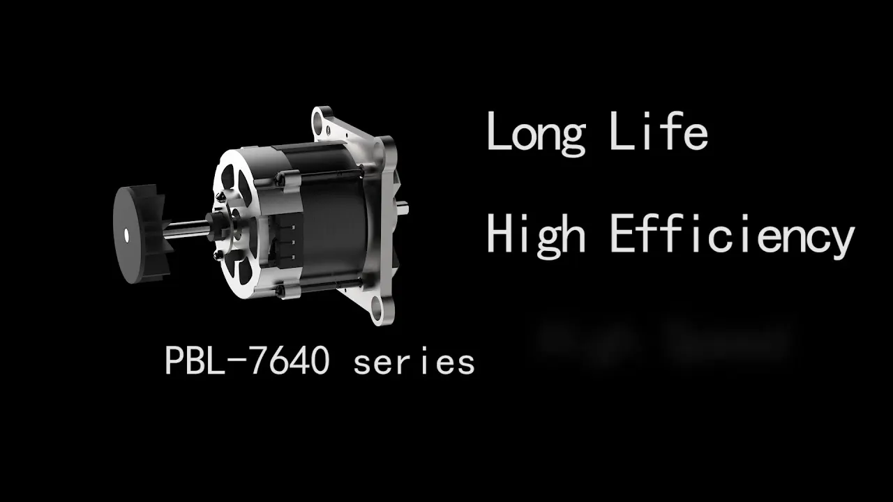
Brushless DC motors have their up and downsides, especially when used in certain applications. These should inform your decision when choosing between a BLDC and brushed motor. The advantages and disadvantages of BL motors are described below, starting with the advantages.
Brushless DC Motor Advantages
The benefits off a BLDC motor include:
- Efficiency- with a BLDC motor, you get more torque per watt ratio. Reasons for the high efficiency include the fewer moving parts, pulsed power control, and reduced power losses since it uses no sliding contacts.
- High Torque to Weight Ratio– when designing a brushless DC motor, its working principle allows engineers miniaturize parts without a significant reduction of torque. These motors are commonly used in small electric products where brushed motors would be too big.
- Low Noise- because they do not use brushes and sliding contacts, BLDC motors do not produce a lot of noise. That explains one of the reasons for their use in computer parts such as fans and hard disks, among other low-noise applications.
- Longer Lifespan- with fewer wear parts, brushless motors last a long time. Most BL motors provide more than 10 000 hours of service life, which is one of the longest lifespan for an electric motor.
- Safe Operation– brushless DC motors do not produce sparks when in operation, which makes them suit environments where sparks could ignite vapor and start a fire. These include hospitals and factories. In brushed motors, the mechanical switching of voltage that happens between the brushes and commutator and leads to arcing.
- Effective Cooling- the brushless DC construction involves placing coil windings on the outer casing of the motor assembly. This helps with cooling through conduction. BL motors also use pulsed power and do not produce a lot of heat.
- Sealed Construction- with the low heat generated by BL motors and heat dissipation through conduction, brushless motors usually do not need to be actively cooled by air. This allows for closed assemblies, shutting off dust and other elements that would cause damage.
- Reduced Electromagnetic Interference– BLDC motors do not cause Electromagnetic interference(EMI). The commutation is electronic, which allows for a smooth change of current direction.
- Reduced Centrifugal Force on Rotor- the brushless DC motor rotor is normally a permanent magnet or magnets. That means reduced centrifugal force when the motor is working, and a better dynamic response.
- Reduced Maintenance Costs- brushless motors are easier and less costly to maintain. There are neither brush wear to worry about no commutator erosion to take care of. Only the bearing is bound to wear out, which is usually after many hours of service.
Brushless DC Motor Disadvantages
A BLDC motor also has its downsides, which makes it unsuitable for specific uses. The disadvantages include:
- High Initial Cost- the brushless DC motor price is one of the highest, and can go up to several hundred dollars for the large types of the motor. Reasons for the high cost include the electronic controllers used with them and the inclusion of sensors in the assembly.
- Delicate Electronics and Sensors- BL motors rely on electronic controllers and (often) sensors to operate. These parts limit the use of the motors in harsh environments such as dusty conditions.
- Need for Gear Reduction- the high RPM of BLDC motors makes them unsuitable for low-speed use such as drive applications. When used in such situations, a gear reduction system is normally requires, which increases costs.