Week-7 Challenge: DC Motor Control
DC MOTOR CONTROL
AIM:
- Run MATLAB demo speed control of a DC motor using BJT H-bridge modify the model such that armature current dose not shoot up when motor changes direction from forward to reverse.
- Refer to help section of the four-quadrant chopper DC drive (DC7) block Compare it with H-bridge model
- Make a suitable EV model using DC 7 block and make result report
Speed control of a DC motor using BJT H-bridge
This example shows the simulation of an H-bridge used to generated a chopped voltage and to control the speed of a DC motor.
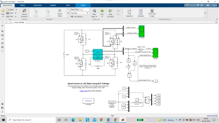
The bipolar junction Transistor (BJT) when used of power switching application operates as an IGBT when it is conducting (BJT operating in the saturated region) a forward voltage VF is developed between collector and emitter in the IGBT block can be used to model the BJT device.
The IGBT block does not simulate the gate current controlling BJT or IGBT. The switch is controlled by a Simulink signal (1/0). The DC motor uses the present model (5hp 24v 1750rpm). It simulates a fan type load where load torque is proportional to square of speed. The armature mean voltage can be varied from 0to 240 V when the duty cycle (specified in the pulse generate block) is varied from 0 to 100%
The H-bridge consists of four BJT /diode pairs (BJT simulated by IGBT models). Two transistors are switched simultaneously: Q1 and Q4 or Q2 and Q3. When Q1 and Q4 are fired a positive voltage is applied to the motor and diodes D2-D3 operate as free wheeling diodes when Q1 and Q4 are switched off. When Q2 and Q3 are fired a negative voltage is applied to the motor and diodes D1-D4 operate as free wheeling diodes when Q2 and Q3 are switched off
Simulation:
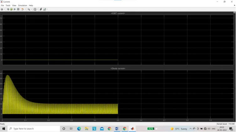
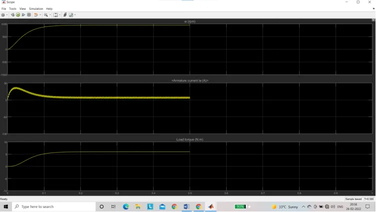
The motor starts in the positive direction with a duty cycle of 75% DC voltage of 180V. at t=0.5sec the armature voltage is suddenly reversed and the motor run in the negative direction.
Scope shows motor speed armature current and load torque and Currents shows currents following in BJT Q3 and diode D3.
The block has two values as a display of the output. One is the current output for the IGBT and the diode current and the other is the scope for the diode current and the other is the scope for the values of the DC motor. The values of the DC motor. The values of the DC motor include
- Speed (in RPM)
- Armature current (in AMPS)
- Load torque (in N-M)
The output values are as follows
- IGBT current
- Diode current
Refer to help section of the four- quadrant chopper DC Drive (DC7) block compare it with H-bridge model
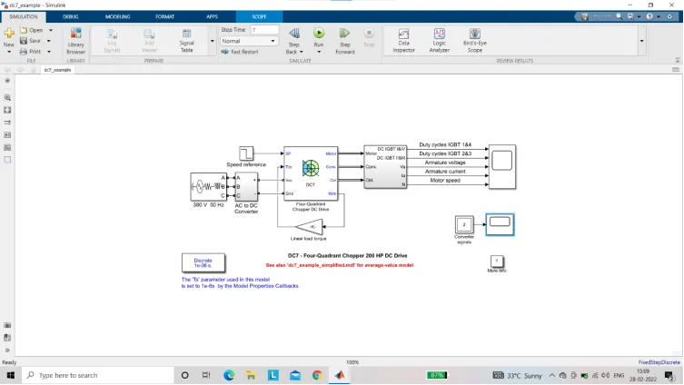
The above model consists of 3 phase source AC-DC converter includes rectifier and braking chopper 4-quardrant chopper DC motor drive and Quadrant selector
A chopper is a static device that converts fixed DC into a variable DC output voltage directly. Essentialy a chopper is a electronic switch that is used to inter put one signal under the control of another. Due to this current and voltage spike occurs. To avoid this RC circuit used
The chopper is widely used in motor control and in regenerative braking. A snubber is an electrical device that prevents voltage spike or transient can damage the circuit and cause arcing RC snubber which is composed of a resistor parallel with a capacitor
Transient are usually caused by switches in the circuit
Applications of four quadrant operation:
- Compressor, pump and fan type load requires operation in the 1 quadrant only. As their operation is unidirectional they are called one quadrant drive system
- Transportation drives require operation in both directions
- If regeneration is necessary application in all four quadrants may be required if not then the operation is restricted to quadrants 1&3 and thus dynamic braking may be required
- In hoist drives a four quadrant operation is needed
4- quadrant DC7 chopper block
- Regenerative braking is possible
- The current values are chopped not continuous hence simulation take less time
- It is widelt used in automobile to control DC motor speed and direction
- To change to direction pf motor current signals are interrupted with one another
DC motor BJT H bridge Block:
- Regenerative braking is not possible but dynamic braking can be achieved
- The current values are continuous
- It is widely used in Robotics and electro mechanical device to control DC motor speed and direction
- To change the direction of motor only the polarity of the current is changed
3)
Make a suitable EV model using DC 7 block and make result report
The EV model create from the DC7 block is as follows
In this model the speed converter block is replace by a drive block the drive cycle used is FTP75 drive cycle. For the simulation we also change the sampling time there were many comparision that were made with the original block of the DC7 motor
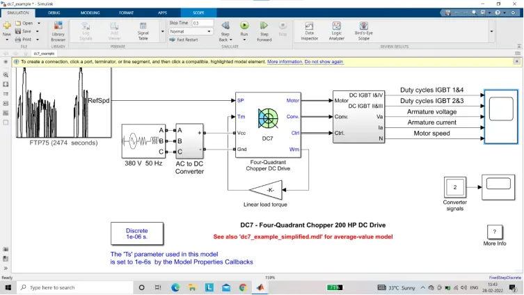
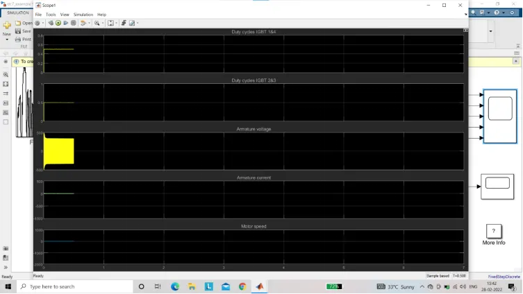
As we can see clearly that the values from the drive have change once the drive cycle was added. The drive cycle has stabilized a bit more since we simulate on the drive cycle. The duty cycle has also changed and reduced to about 12% the drive
When we observe the armature voltage fluctuation the voltage fluctuation has decrease on the drive cycle the maximum armature voltage in the EV vehicle is 380V at a phase frequency of 50HZ
When we look at the armature current it is almost constant at 10Amps but at certain case where it shoots up. This conditions is due to the fact that the motor runs in reverse motoring characteristic is observed
The motor speed characteristics are also plotted in the scope for the EV. These characteristics show that the motor speed is almost constant amongst the starting and then when the reverse motor plot is reached the motor speed increase drastically as well