Week-7 Challenge: DC Motor Control
Speed control of a DC motor using BJT H-bridge
The Bipolar Junction Transistor (BJT) when used for power switching applications, operates as an IGBT. When it is conducting (BJT operating in the saturated region), a forward voltage Vf is developed between collector and emitter (in the range of 1 V). Therefore, the IGBT block can be used to model the BJT device.
The IGBT block does not simulate the gate current controlling the BJT or IGBT. The switch is controlled by a Simulink® signal (1/0). The DC motor uses the preset model (5 HP 24V 1750 rpm). It simulates a fan type load (where Load torque is proportional to square of speed). The armature mean voltage can be varied from 0 to 240 V when the duty cycle (specified in the Pulse Generator block) is varied from 0 to 100%.
The H-bridge consists of four BJT/Diode pairs (BJT simulated by IGBT models). Two transistors are switched simultaneously: Q1 and Q4 or Q2 and Q3. When Q1 and Q4 are fired, a positive voltage is applied to the motor and diodes D2-D3 operate as free-wheeling diodes when Q1 and Q4 are switched off. When Q2 and Q3 are fired, a negative voltage is applied to the motor and diodes D1-D4 operate as free-wheeling diodes when Q2 and Q3 are switched off.
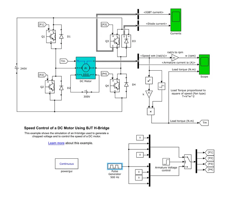
The DC motor is connected with Chopper to have varying voltage to suit the load requirement.
The Chopper is the one type of power converters here H-Bridge BJT is used to control the speed of the motor.
The H bridge has 4 BJT diode. out of 4, two pairs either Q1& Q4 or Q3&Q2 will be in close condition and which allos the current to flow through. and changes the magnetic field when its swictching between the diode and thus creating the RMF which inturn roate the Rotor
so the initial model is run from the default settings
as duty cycle as 75%
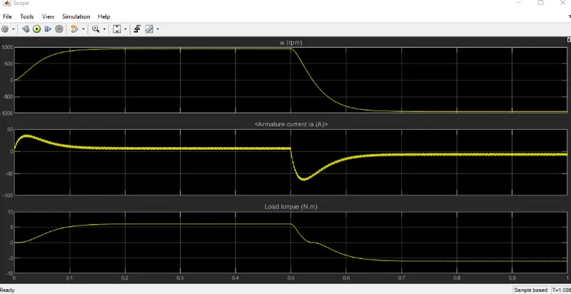
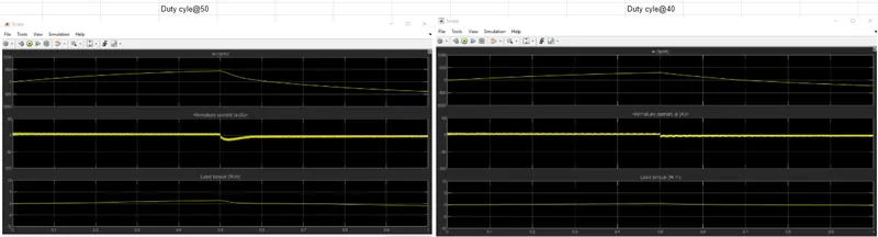
At 75% duty cylce, the initial current is more and then it becames stable. this raise in initial current is due to the switching change over.
and in duty cyle 50% and 40%, the current is almost constant so if the duty cycle is reduced the variation in the current will be reduced and its related losses.
---------------------------------------------------------------------------------------------------------------------------------------------------------
The Four-Quadrant Chopper DC Drive (DC7) block:
The Four-Quadrant Chopper DC Drive (DC7) block represents a four-quadrant, DC-supplied, chopper (or DC-DC PWM converter) drive for DC motors. This drive features closed-loop speed control with four-quadrant operation. The speed control loop outputs the reference armature current of the machine. Using a PI current controller, the chopper duty cycle corresponding to the commanded armature current is derived. This duty cycle is then compared with a sawtooth carrier signal to obtain the required PWM signals for the chopper.
The main advantage of this drive, compared with other DC drives, is that it can operate in all four quadrants (forward motoring, reverse regeneration, reverse motoring, and forward regeneration). In addition, due to the use of high switching frequency DC-DC converters, a lower armature current ripple (compared with thyristor-based DC drives) is obtained. However, four switching devices are required, which increases the complexity of the drive system.
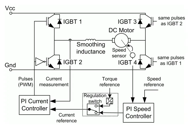
The Four-Quadrant Chopper DC Drive block uses these blocks from the Electric Drives/Fundamental Drive Blocks library:
-
Speed Controller (DC)
-
Regulation Switch
-
Current Controller (DC)
-
Chopper
- Bellow are the Chopper circuit diagram
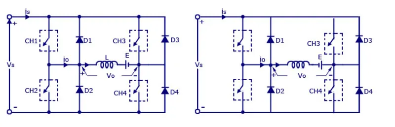
As shown above the The four c quadrant choppers consist of four semiconducts switches and 4 diodes in antiparallel connection.
they are numbered according to the quadrant they belong.
First Quadrant:
When CH1is ON and CH4 are operated , the load voltage Vo is equal to the source voltage Vs
and the load current Io will begin to flow.
Vo and Io will be positive when the first quadrand operation take place. As soon as the chopper CH1 is turned off
the positive current freewheels to CH4 and diode D2. This acts as a step down chopper in first quadrand.
Second Quadrant:
Only CH2 is ON, and other three are kept OFF, when CH2 is ON , the negative current flow throught CH2,L ,E & D4
Energy is stored in the inductor L when CH2 in ON.
when CH2 is OFF, the current fled back to the source through diode D1 & D4.
The Chopper acts as Step-Up chopper in second quadrant.
Third Quadrant:
THe CH2 is ON & CH3 are operated.
when CH3 is ON the load gets conneted to the source Vs.
Vo and Io will be negative and this chopper acts as Step-down chopper in Third quadrant.
Fourth Quadrant:
Only CH4 is ON and other are kept OFF,
the positive current flow through CH4, D ,E and the Inductor L will store the energy.
when CH4 is OFF the current fed backs to the source throug D2 and D3.
This acts as Step Up chopper in this quadrant.
Comparison between 4 Quadrant and H bridge
| # | 4- Quadrant | H- Bridge |
| 1 |
The motor can be operated in all 4 different modes (Forward motoring, Reverse motoring, Forward braking and Reverse breaking) |
In H-Bridge , the motor can be operated only in two modes (Forward motoring & Reverse motoring) |
| 2 | Regenerative braking is possible | Regenarative braking is not possible |
| 3 | Widely used in Electric cars in Automobile | Used in Robotics and Electromechanical devices to control speed and direction at low speed |
| 4 | Vehicle control is better | Vehicle control is less |
| 5 | The signal given tothe 4 quadrand are discrete | Here the signal are continuous |
----------------------------------------------------------------------------------------------------------------------------------------------------------
Develop a 2-quadrant chopper using simulink & explain the working of the same with the relevant results. (Refer to article - Multiquadrant operation of motor )
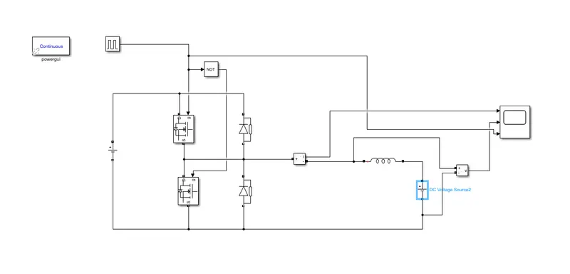
The above model is the 2 quadrand chopper:
It uses two Mosfet and two diode blocks
Current and Voltage measurement block are used to take the output to scope.
NOT gate is used to make sure that at any time only one mosfet should be ON to avoid short circuit
Operation principle:
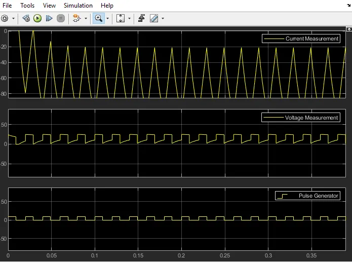
When one Mosfet 1 is ON, the voltage and current is positive and when it is OFF the current is negative and the Voltage remains positive
-----------------------------------------------------------------------------------------------------------------------------------------------------------
Explain in a brief about operation of BLDC motor
What is Brushless DC motor?
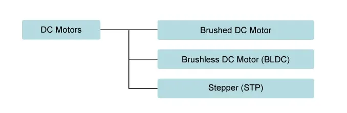
A motor converts supplied electrical energy into mechanical energy. Various types of motors are in common use. Among these, brushless DC motors (BLDC) feature high efficiency and excellent controllability, and are widely used in many applications. The BLDC motor has power-saving advantages relative to other motor types
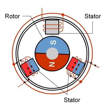
Since the rotor is a permanent magnet, it needs no current, eliminating the need for brushes and commutator. Current to the fixed coils is controlled from the outside.
Advantage of BLDC motor:
A BLDC motor with three coils on the stator will have six electrical wires (two to each coil) extending from these coils. In most implementations three of these wires will be connected internally, with the three remaining wires extending from the motor body (in contrast to the two wires extending from the brushed motor described earlier). Wiring in the BLDC motor case is more complicated than simply connecting the power cell’s positive and negative terminals; we will look more closely at how these motors work in the second session of this series. Below, we conclude by looking at the advantages of by BLDC motors.
One big advantage is efficiency, as these motors can control continuously at maximum rotational force (torque). Brushed motors, in contrast, reach maximum torque at only certain points in the rotation. For a brushed motor to deliver the same torque as a brushless model, it would need to use larger magnets. This is why even small BLDC motors can deliver considerable power.
The second big advantage—related to the first—is controllability. BLDC motors can be controlled, using feedback mechanisms, to delivery precisely the desired torque and rotation speed. Precision control in turn reduces energy consumption and heat generation, and—in cases where motors are battery powered—lengthens the battery life.
BLDC motors also offer high durability and low electric noise generation, thanks to the lack of brushes. With brushed motors, the brushes and commutator wear down as a result of continuous moving contact, and also produce sparks where contact is made. Electrical noise, in particular, is the result of the strong sparks that tend to occur at the areas where the brushes pass over the gaps in the commutator. This is why BLDC motors are often considered preferable in applications where it is important to avoid electrical noise.