Week-7 Challenge: DC Motor Control
AIM :DC motor control .
objective:
1.A Explain a MATLAB demo model named speed control of a DC motor using BJT H-bridge
B. comment on the armature current shoot-up from the scope result.
C. refer to the help section of the four-Quardrant chopper DC drive (DC7)block compare it with the H- bridge model.
2. develop a -2 quadrant chopper using simulink & explain the working of the same with the relevant result .(refer to article . multiquadrant operation of motor.
3.explain in a brief about operation of BLDC motor.
ANSWERS :
1.matlab demo model and speed control of a dc motor using BJTH-bridge:
An general H-bridge is a simple circuit that us to control a DC motor to go backward or forward
in general an H- bridge is a rather simple circuit .conttaining four switching elements ,with the load at the centre ,in an H- like congfiguration.
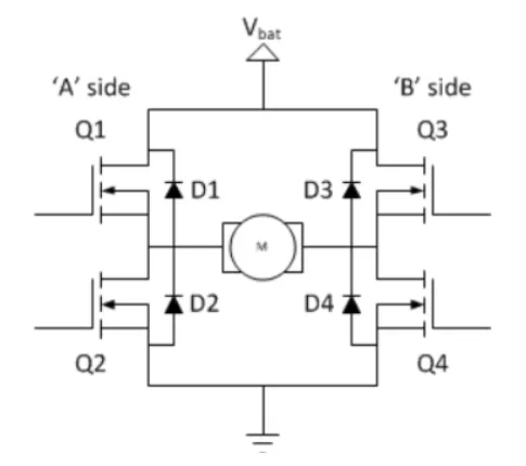
the switching elements(Q1 .Q4) atre usually bi-polar or FET transistors,in some high -voltage application IGBTs integrated solution also exist but wheather the switching elements are integrated with their control circuits or not relevant for the most part for this dicussion .the diodes (D1.D4) are called catch diodes and are usually of a schotty types
the top-end of the bridge is connected to a power supply (battery for example ) and the bottom -end is grounded.
in general all four switching elements can be turned on and off independing ,thorugh there are some obvious restriction.
through the load can anything we want by far the most pervasive application .if H-bridge is with a brushed DC or bipolar stepper motor (steppers need two H-bridges per motor )load. in the following we will concentrate on application as a brushed DC motor driver.
static operation:
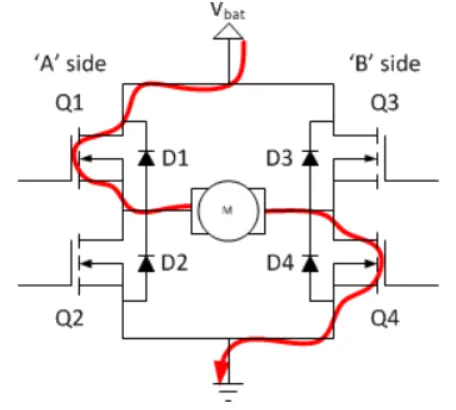
the basic operating mode of an H-bridge fairly simple Q1 and Q4 are turned .the left of the motor will be connection to the power supply .while the right lead is connected to ground current start flowing the motor which energies the motor in (left say ) the forward direction and the motor shaft spining .
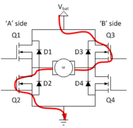
if Q2 and Q3 are turned on the reverse with happen the motor gets engering in the revers direction and the shaft will start spining backwards.
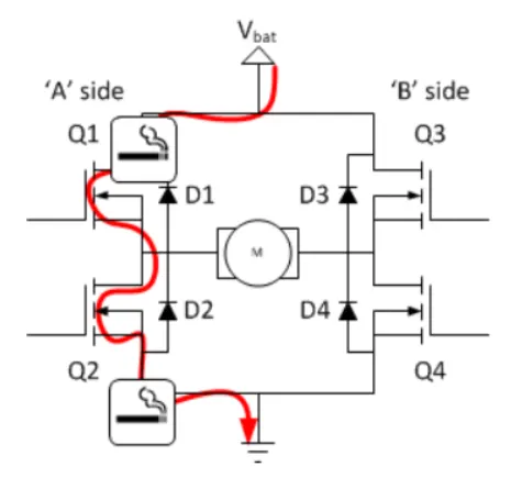
in a bridge you should never ever close both Q1 and Q2 and Q3,Q4 at the same time ,if you did that you just have created a really low resistance path between power and GND effectively short-circuiting your power supply .this condition is called short through and is an almost guaranteed way to quikly destroy your bridge or something else in your circuit.
MATLAB demo model named speed control of a DC motor using BJT,H -bridge show below.
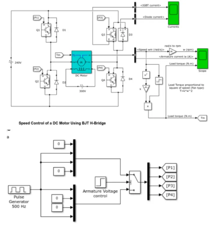
the bipolar junction transistor (BJT) when used for power switching applictions, operetes as an IGBT when it is conducting (BJT)operating in the saturated region ,a forward voltage vf is developed between collector and emmiter (in the range of iv) IGBT block can be used to model the BJT drive .
the IGBT block does not simulate the gate current controlling the BJTT, the switch is controlled by a simulate signal (I/O),
model description:
1. DC motor used in model is present model (5HP-24v1750 RPM) it simulates a fan type loade torque is proportional to square of speed ).the armature mean voltage can be varied from 0 to 24v when the duty cycle (specified in the pulse generator block ) is varied from 0 to 100%
2.the H-bridge consists of four BJTs / diodes pairs (BJTs simulated by IGBTs model)
3.two transistors are switched simulatneously Q1and Q4 or Q2 and Q3 when Q1 and Q4 are fired a positive voltage is appliction to the motor and diodes D2,D3 operate as free -wheen ling diodes when Q1are Q4 are switched off
4.when Q2 and Q3 are fired ,a negative voltages is applied to the motor and diodes D1-D4 operate as a free -wheeling diodes when Q2 and Q3 are switched off.
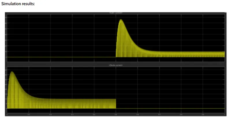
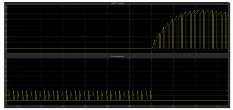
thus from the above graph we can see that for 0 to 0.5 sec .the current flows through diode D3 and from 0.5 sec, the current flows through
Q3.
the motor starts in the positive direction with a duty cycle of 75% (means DC voltages of 180v ) at t= 0.5 sec ,the armature voltages is suddenly reversed and the motor runs in the negative direction .
scope ' shows motor speed armature current and load torque and current shows currents flowing BJT Q3 and diode D3
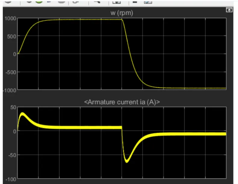
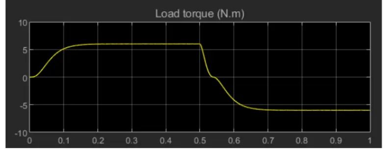
the wave from speed armature current and torque shows in above graphs
from armature current graph ,we can see that ,starting there is sudden spike increase in current at 0sec and at 0.5 sec also we can see tha as the voltage gets changed in the circuit the speed motor also changes
as there is already current flowing in the circuit on changing after 0.5 sec the current inthe circuit adds to changed direction of current and we observe a surge.
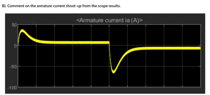
from armaure current graph ,we can see that ,at starting there is sudden spike increase in current at 0 sec also and at 0.5 sec and also means at transition from positive to negative direction of rotation we observe a high surge in current this due to the transient switching occuring in the circuit.
the surge in the current can be reduced by reducing the duty cycle
in above results duty cycle selected as 75%
by changing the duty cycle from 75% to 50% inthe current can reduced tremendously.
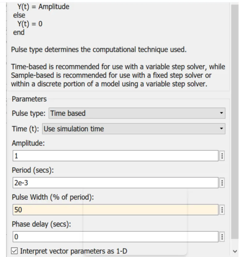
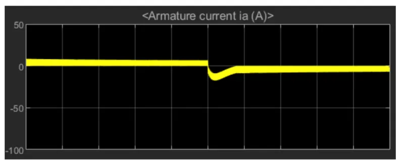
thus we can find that armature current spike is reduced by changing the duty cycle from 75%to 50%
c) refer to the help section of the four Quadrant chopper DC drive (DC7) block ,compare it with the H- bridge model:
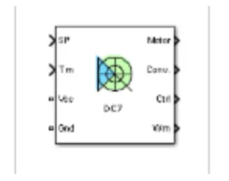
the four quadrant chopper DC drive (DC7) BLOCK represent a four -quadrant DC supplied chopper (dc-dc-pwm ) converter drive for motor this device features closed -loop speed control four quadrant operation .the speed control loop output the reference armature current of the machine using a pi current control the chopper duty cycle corresponding to the commanded armature current is derived this duty cycle is then compared with a sawtooth carrier to obstain the required PWM signal for the chopper.
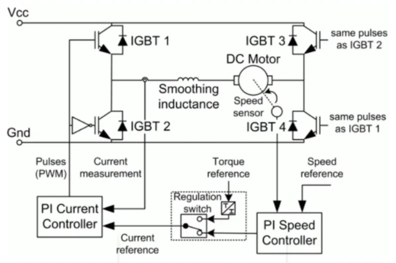
the machine is seperatly excited with a constant DC field voltage source .thus there is no field volitage control by default ,the field current is set to its steady -state value when simulation is started .
the armature voltage is provided by an IGBT converter controlled by two PI regulation the converter is fed by a constant dc voltage source armature current oscillation are reduced by a smothing induction connected in series with the a armature circuit.
working of four quadrant chopper .
the circuit of a four quadrant chopper or clss-E chopper basically consists of four semiconductor switches CH1 to CH4 and four diodes D1 to D4 the four are connected in anti -parallel the circuit daigrom of this types of chopper is shown below.
in the above circuit daigram ,the chopper are numbered CH1 to CH4 for first quadrant operation CH1 is made ON for second quadrant operation CH2 is made ON and so .on to better understand the working of four quadrant chopper, we will discuss its operation seperately for each quadrant.
the circuit daigarm of Class-chopper
comparision of a 4 quadrant chopper and its H-bridge:
1.in the 4 quadrant chopper works in all four mode like
*forward motoring
* forward breaking
*reverse motoring
*reverse breaking
but the BJTH- bridge model works on only two modes
*forward motoring
* reverse motoring
2.to change the direction of rotation of motor from forward to reverse and vice versa. the current signal get trasited from one to other switch while in H- bridge model, the direction of rotation of motors is changed by changing the polarity of current.
3.the 4 quadrant chopper have hivgh switching frequency . whil H bridge model have slow switching frequency.
4.the armature current 4 quadrant chopper have a littel spike at trastion from one to other switch because of high switching frequency while h- bridge model have high spike of current.
5.the 4 quadrant chopper is generally used in industrial appliction while H- bridge model is used in robotics.
2.Develop a 2-quadrant chopper using simulink & explain the working of the same with the relevant result (refer artical -multi quadrant operation of motor )
circuit daigram for two quadrant chopper
two quadrant chopper by using simulink model :
let us take two mosfet blocks and diodes blocks and connect it as shown in circuit daigram .
the DC voltage source is connected as shown
let the voltage of DC voltage source be 24 volts
let us consider an series RLC branch block and select inductor . thus blocks works as a load.
to consider LE load i....e motor load and DC voltage source of 12 volts is also connected in series with inductor
scope results:
the voltage wave form is not going less than zero .the minimum value of voltage zero and maximum value is always in the positive direction.
however in current waveform ,the current increases and decreases .the current may be positive as well as negative and the pulse amplitude is 10 thus from pulse waveform we can see that pulse amplitude is 10.
3.Explain in a brief about operation of BLDC motor .
BLDC MOTOR :
brushless DC electric motors also known as electricity commutated motor a brushless DC motor is a permanent magnet syncronus electric motor while is drive current DC electricity and it accomplishes electronically controlled commulation system
unlike conventional brushed type DC motor ,where in the brushles make the mechanical contact with commutator on the motor so as to from an electric path between a DC electric source and rotor armature winding ,BLDC motor employes electrical commutation with permanent magnet rotor and a stator with a sequence of coils.in this motor ,permanent (or field poles) rotates and current cerrying conductors are fixed.
brushless motor does not have any current carrying commutators .the field inside a brushless motor is switched through an amplifier which triggered is by the commutation device like an optical encoder.
BLDC motor can be constructed in different physical configuration . deepending on the stator winding .these can be configuredas single phase two -phase or ,three -phase motor .however ,three -phase BLDC motor with permanet magnet rotor are most commonly used.
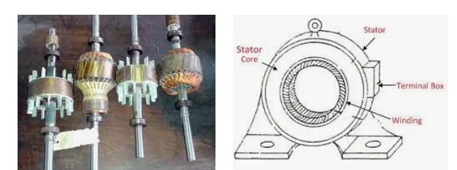
the construction of this motor has many similarities three phase induction motor as well as conventional dc motor this motor rotor and stator like parts of other motor.
stator. rotor.
working of BLDC motor :
BLDC motor work on the principle similar to that of a brushed DC motor .though the source of supply is DC switching makes to generate an AC voltage wave form with trapezoidal shape .due to the force of interaction between electromagnet rotor,the rotor continues to rotate .
Advantages of BLDC motor .
* less over all maintainance due to absence of brushes
*reduced of size with far superior thermal charcteristics
*higher speed range and lower electric noise generaion
*low electromagnetic interference
* i has no mechanical commutator
Disadvantages of BLDC motor:
*these motor are costly
*electronic controller required control,this motor expensive
*requires complex drive circuit
*need of additional sensors
application of BLDC motor:
*computer hard drive and DVD/CD players
*electric vehicles hybrid electric vehicles and electric bycles
*fans pumps and blowers
*washing machines compressors and dryers
*indutrial robots ,CNC machine tools and simple belt driven system
conclusion:
*MATLAB demo model named 'speed control of a DC motor using BJT H -bridges is studied and the armature current shoot-up is studied and the four -quadrant chopper DC drive (DC7) block compare it with the H- bridge model.
*2-quadrant chopper using simulink is model is made the various result obtained is studied
*operation of BLDC motor is studied.