Week-7 Challenge: DC Motor Control
ANS 1:
In the MATLAB/SIMULINK documentation, we can search for the simulation model of the 'Speed control of a DC Motor using BJT H-bridge’.
It is used to generate a chopped voltage and to control the speed of the DC motor. This model can be opened in SIMULINK from the documentation itself. As the name suggests, it uses a BJT (Bipolar Junction Transistor which is a type of transistor that uses both electrons and holes as charge carriers, hence the name bipolar. Other transistors such as FETs (Field Effect Transistors) are unipolar transistors meaning that they only use one type of charge carrier. BJTs are used for switching and amplifying applications. BJTs have 3 terminals which are: the emitter (E), the base (B) and the collector (C). Current flows in only the emitter and the collector and the amount of current that flows through them is controlled by the base. BJTs use semiconductors in their working.
there are 2 types of BJT: NPN type and PNP type
- PNP Transistor
This type uses 2 p-type semiconductors and one n-type semiconductor. The n-type semiconductor will be the base of the transistor. The emitter terminal is more positive in relation to the collector and base terminals. The collector is connected to positive supply and emitter is connected to negative supply. The base terminal is supplied with voltage and it operates the transistor by switching between ON or OFF states. When the base voltage is the same as the emitter voltage, the transistor is in the OFF state. When the base voltage decreases with respect to the emitter voltage, the transistor is in the ON state.
- NPN Transistor
This type uses 2 n-type semiconductors and one p-type semiconductor. The p-type semiconductor will be the base of the transistor. Construction wise it is exactly the same as the PNP type having 3 terminals. Just as in the PNP type, the collector terminal is conneced to the positive voltage supply and the emitter terminal is connected to the negative voltage supply. The base terminal is supplied with a voltage and controls the transistor being either in an ON or OFF state. When the base voltage is the same as the emitter voltage, the transistor will be in the OFF state. When the base voltage increases with respect to the emitter voltage, the transistor will be in the ON state.
- BJT H-Bridge
When the BJT is conducting i.e. operating in the saturated region, there will be a forward voltage developed between the collector and the emitter (in the range of 1V). An IGBT is used to model the BJT because of this. The switch is controlled by a SIMULINK signal. The DC motor used in this model is pre-set to with specifications: 5HP, 24V, 1750rpm. It simulates a fan type load where the load is proportional to the square of the speed. The mean armature voltage can be varied between 0 and 240V when the duty cycle is changed anywhere from 0 to 100%. The duty cycle can be changed from the pulse generator block. The H-bridge consists of 4 BJT and Diode pairs. Two transistors are switched on simultaneously: Q1 and Q4 or Q2 and Q3. When Q1 and Q4 are fired, a positive voltage is applied to the motor and the diodes, D2 and D3 operate as free wheeling diodes when Q1 and Q4 are switched off. Similarly, when Q2 and Q3 are fired, a negative voltage is applied to the motor and the diodes, D1 and D4 operate as free wheeling diodes when Q2 and Q3 are switched off. By default, the motor will start in the positive direction and has a preset duty cycle of 75% with a mean DC voltage of 180V. At t = 0.5 seconds, the armature voltage will reverse and the motor will run in the negative direction.
This is the SIMULINK model for the BJT H-Bridge used in the speed control of a DC motor:
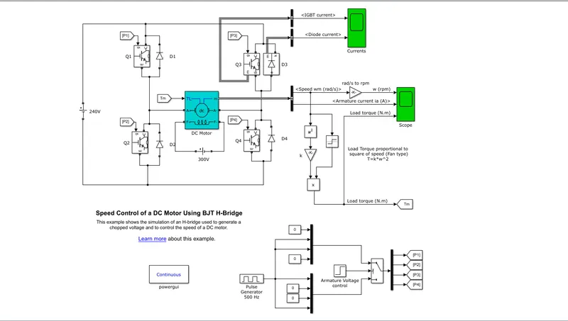
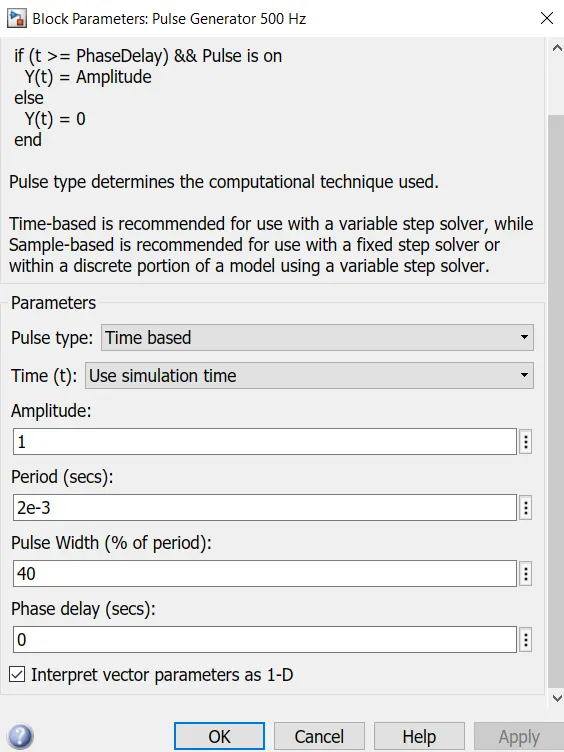
here we get pilse genearator 500HZ block where we can see setting of duty cycle attached below:-
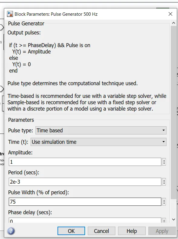
As we can see, the pulse generator is already preset with some settings. The pulse width field allows us to modify the duty cycle of the motor and hence, we can prevent the motor current from shooting up when the motor changes its direction from forward to reverse. By default the duty cycle is 75% meaning that the voltage is supplied to the motor for 75% of the time for one cycle. For the remaining 25%, the motor is off and receives no voltage from the source. It is this alternation between the ON and OFF states, that allows us to vary the voltage that is supplied to the motor and thereby control the speed of an electric vehicle. The image below shows the output of the scope when the simulation is run using the preset values in the pulse generator block. There are 3 output graphs of angular speed, armature current and the load torque all against a time axis.
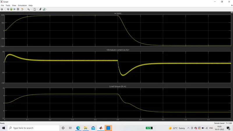
For this question, we are interested in modifying the simulation in order to prevent the initial shoot up of the armature current at the start of the cycle. This shootup occurs whenever the armature voltage reverses direction which is every 0.5 seconds. In the second graph above (which shows the armature current vs. time) we can see that at the start of the cycle, there is a sharp increase in the armature current that then decreases and comes to a more stable level where it remains until 0.5 seconds. When the next cycle begins, the exact same effect occurs but in the negative axis because in this cycle, the armature voltage is reversed.
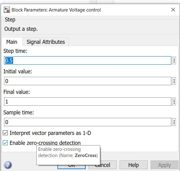
This frequency of reversing the voltage direction has been preset in the 'armature voltage control' block. Opening it will give you a dialog box of its setting where the 'step time' field controls the frequency at which the voltage is reversed.
If we change the duty cycle i.e. the pulse width, we can control this initial shoot up of the current that occurs every time the armature voltage direction is reversed. When the duty cycle is decreased to 40 the output graph that is obtained is shown below.
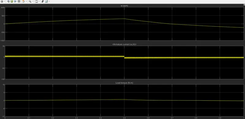
Here, we can see that at the start of the cycle in the positive armature voltage direction, the armature current does not shoot up like it did before. The armature current increases immediately to approximately 7A and it maintains that level until the next cycle where the armature voltage is reversed to -7A.
ANS 2
The four quadrant chopper DC drive block in MATLAB/SIMULINK represents a four quadrant, DC supplied chopper drive for DC motors. It is also referred to as the 'DC7' motor drive in SIMSCAPE. It features closed loop speed control with four quadrant operation. The closed loop speed control will output the armature current of the machine. Using a Pl current controller, the chopper duty cycle corresponding to the commanded armature current is derived. The duty cycle is then compared with a sawtooth carrier signal to obtain the required PWM signals for the chopper.
Compared to other DC drives, the main advantage of using the four quadrant chopper DC drive is that it can operate in all 4 quadrants. Each quadrant in its characteristics represents a different mode of operation. The first quadrant is forward motoring, the second is reverse braking, the third is reverse motoring and the forth is forward braking. Another advantage is that it uses high switching frequency DC-DC converters resulting in a lower armature current ripple is occurs than compared to thyristor based DC drives.
The four quadrant chopper DC drive uses these 4 main blocks from the fundamental drive blocks library:
- speed controller
- current controller
- regulation switch
- chopper
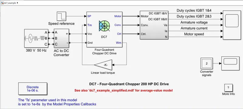
4 quadrant chopper DC drives are used mainly due to their ability to work in the 4 different quadrants of operation. It allows the controller to command the DC motor to rotate in clockwise and counter clockwise directions and to perform braking. Traditional DC motors would rely on the innate friction and air resistance forces or actual physical brakes to bring the motor to rest. The other simpler option is to switch off the motor till it comes to rest.
Operation
• Forward Motoring: motor rotates clockwise and controller applies a clockwise drive.
• Reverse Motoring: motor rotates anti-clockwise and controller applies an anti-clockwise drive.
• Forward Braking: motor rotates clockwise and controller applies anti-clockwise drive.
• Reverse Braking: motor rotates anti-clockwise and controller applies a clockwise drive.
Advantages
4 quadrant choppers have more control over the deceleration of the motor and can more accurately brake the motor. This will make the deceleration more smoother. The second benefit is that it reduces the risk of current spikes (and possibly damage the motor and the controller) which can occur when the motor is made to brake while running at a high speed. So the controller life is generally longer with 4 quadrant choppers. A third advantage is that 4 quadrant choppers are more efficient because lesser energy is wasted as heat and lesser current spikes occur which means lesser power dissipation. Finally, the 4 quadrant chopper makes regenerative braking possible so that when the motor is made to brake, the kinetic energy of the rotor moving is transferred back as electrical energy which can then be used to charge a battery.
Comparison to H-Bridge:-
Both BJT H-bridges and 4 quadrant choppers have their advantages and disadvantages. H-Bridges like the 4 quadrant choppers are also capable of the braking operation without using air resistance or friction or physical brakes to bring the motor to rest. 4 quadrant DC choppers are more commonly used in automobiles whereas BJT H-bridges are commonly used in robotics and electro-mechanical devices.
Unlike 4 quadrant DC choppers, BJT H-bridges are not capable of performing regenerative braking but they can perform dynamic braking. It is this difference that makes 4 quadrant DC choppers useful in hybrid and electric vehicles.
In 4 quadrant DC choppers, the current signals are interrupted with one another to change the direction of rotation of the motor. This is done by a speed reference or a drive cycle from which the speed values are converted to current signals which interrupt one another to change the rotation of direction of the motor.
However in BJT H-bridges, the polarity of the current is reversed (depending on the duty cycle) to change the direction of rotation of the motor.
Also, the current signals in 4 quadrant DC choppers are chopped meaning that they are not continuous, they are discrete and so take less time for simulations. But in BJT H-bridges, the current values are not chopped, meaning that they are continuous and so take more time for simulations.
Finally, in 4 quadrant DC choppers, a Pl controller is used to control the speed and the current and in the H-bridge, this is not implemented.
Q-2:-Develop a 2-quadrant chopper using simulink & explain the working of the same with the relevant results.
ANS:-
Two Quadrant Chopper DC Drive Block:
The Two-Quadrant Chopper DC Drive (DC6) block represents a two-quadrant, DC-supplied, chopper (or DC-DC PWM converter) drive for DC motors. This drive features closed-loop speed control with two-quadrant operation. The speed control loop outputs the reference armature current of the machine. Using a Pl current controller, the chopper duty cycle corresponding to the commanded armature current is derived. This duty cycle is then compared with a sawtooth carrier signal to obtain the required PWM signals for the chopper. The main advantages of this drive, compared with other DC drives, are its implementation simplicity and that it can operate in two quadrants (forward motoring and reverse regeneration). In addition, due to the use of high switching frequency DC-DC converters, a lower armature current ripple (compared with thyristor-based DC drives) is obtained. However, for all two-quadrant DC drives, reversible and regenerative operations (reverse motoring and forward regeneration), which are required in most DC drives, cannot be obtained.
The Two-Quadrant Chopper DC Drive block uses these blocks from the Electric Drives/Fundamental Drive Blocks library:
- Speed Controller (DC)
- Regulation Switch
- Chopper.
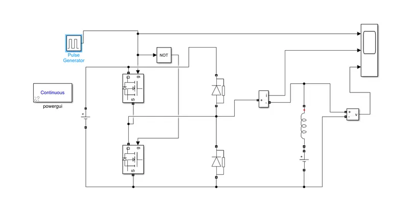
RESULT:-
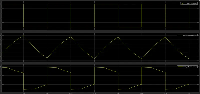
In above result we can see that
- the voltage waveform is not going less than zero.
- the minimum voltage is zero and maximum voltage is always is in positive direction.
- however in current waveform : current increases & decreases , may be psitive or negative
- pulse amplitude is 10 so we can see the pulse amplitude as 10.
3. Explain in a brief about operation of BLDC motor.
ANS:-
BLDC Motor:
A brushless DC electric motor (BLDC motor or BL motor), also known as an electronically commutated motor (ECM or EC motor) or synchronous DC motor, is a synchronous motor using a direct current (DC) electric power supply. It uses an electronic closed looped controller to switch DC currents to the motor windings producing magnetic fields which effectively rotate in space and which the permanent magnet rotor follows. The controller adjusts the phase and amplitude of the DC current pulses to control the speed and torque of the motor. This control system is an alternative to the mechanical commutators (brushes used in many conventional electric motors. The construction of a brushless motor system is typically similar to a permanent magnet synchronous motor (PMSM), but can also be a switched reluctance motor, or an induction (asynchronous) motor. They may also use neodumium magnets and be outrunners (the stator is surrounded by the rotor), inrunners (the rotor is surrounded by the stator), or axial (the rotor and stator are flat and parallel). The advantages of a brushless motor over brushed motors are high power-to-weight ratio, high speed, nearly instantaneous control of speed (rpm) and torque, high efficiency, and low maintenance. Brushless motors find applications in such places as computer peripherals (disk drives, printers), hand-held power tools, and vehicles ranging from model aircraft to automobiles. In modern washing machines, brushless DC motors have allowed replacement of rubber belts and gearboxes by a direct-drive design.
ADVANTAGES OF BLDC MOTOR
- Less overall maintenance due to absence of brushes
- Reduced size with far superior thermal characteristics
- Higher speed range and lower electric noise generation.
- It has no mechanical commutator and associated problems
- High efficiency and high output power to size ratio due to the use of permanent magnet rotor
- High speed of operation even in loaded and unloaded conditions due to the absence of brushes that limits the speed
- Smaller motor geometry and lighter in weight than both brushed type DC and induction AC motors.
- Long life as no inspection and maintenance is required for commutator system
- Higher dynamic response due to low inertia and carrying windings in the stator
- Less electromagnetic interference
- Low noise due to absence of brushes
DISADVANTAGES OF BLDC MOTOR
- These motors are costly
- Electronic controller required control this motor is expensive
- Requires complex drive circuitry
- Need of additional sensors
APPLICATION OF BLDC MOTOR
- Brushless DC motors (BLDC) use for a wide variety of application requirements such as varying loads, constant loads and positioning applications in the fields of industrial control, automotive, aviation, automation systems, health care equipments etc.
- Computer hard drives and DVD/CD players
- Electric vehicles, hybrid vehicles, and electric bicycles
- Industrial robots, CNC machine tools, and simple belt driven systems
- Washing machines, compressors and dryers
- Fans, pumps and blowers.