Week-7 Challenge: DC Motor Control
1. A. Explain a MATLAB demo model named ‘Speed control of a DC motor using BJT H-bridge’.
H- Bridge configuration
DC motors have two terminals they are in series type (armature and field windings are connected in series) DC motors.
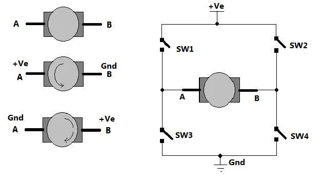
As shown in figure there are two terminals ‘A’ and ‘B’ of DC motor. Now if we connect terminal A with +Ve supply and terminal B with –Ve supply or ground the current will flow from motor from A to B and motor will rotate in one direction – say clockwise (CW) or forward direction. Now as shown in second figure we change the supply terminals. Now B is connected with +Ve and A is connected to ground. The current will flow from motor from B to A and motor will rotate in other direction (counter clockwise – CCW or reverse).
Let see how to give reversible supply to motor?
The arrangement is shown in right side of figure. Four switches are connected in between +Ve supply and ground and DC motor is connected in between two switches as shown. Such circuit arrangement is known as H-bridge because it looks like letter ‘H’ (H-bridge circuits are most widely used in DC motor drivers). Let us see how it gives reverse supply to motor.
If SW1 and SW4 are pressed simultaneously then current will flow from +Ve – SW1 – A – B – SW4 – Gnd. So motor will rotate in one direction. Open (release) SW1 and SW4 to stop motor. Now if SW2 and SW3 are pressed current will flow from +Ve – SW2 – B – A – SW3 – Gnd. So motor gets reverse supply and it will rotate in another direction.
(Caution: care has to be taken that SW1 and SW3 or SW2 and SW4 must not be pressed simultaneously otherwise it will short circuit the supply)
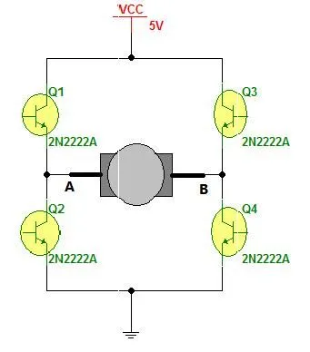
The circuit replaces the switches with NPN type transistors. We all know that transistor works as switch. For NPN transistor if we give +Ve input to base it will turn ON and if we give 0 input it will be turned OFF.
So in this circuit if Q1 and Q4 are turned ON simultaneously the motor will rotate forward and if Q2 and Q3 are turned ON then motor will rotate reverse.
Motor can be rotated forward and reverse using 4 transistors only.
Now let us move to vary the speed of DC motor. The DC motor speed varies as applied input voltage varies. As you increase applied input voltage the speed will increase and vice versa. Applying max rated voltage will rotate motor at full speed (caution: do not apply more than max rated voltage to motor otherwise motor windings may get burnt).
Speed Control of a DC Motor Using BJT H-Bridge
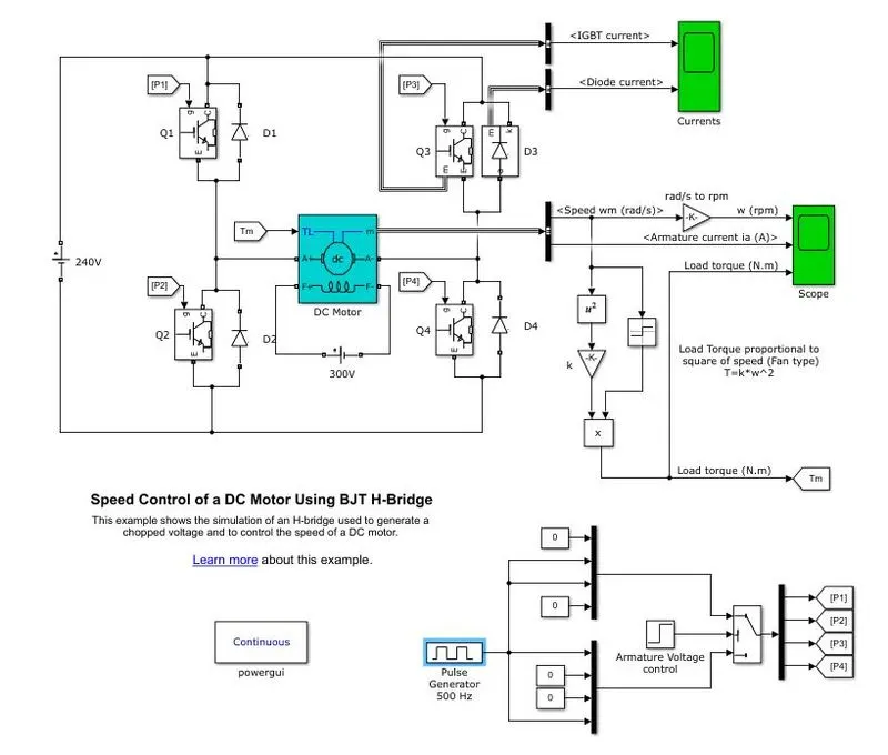
The Bipolar Junction Transistor (BJT) when used for power switching applications, operates as an IGBT. When it is conducting (BJT operating in the saturated region), a forward voltage Vf is developed between collector and emitter (in the range of 1 V). Therefore, the IGBT block can be used to model the BJT device.
The IGBT block does not simulate the gate current controlling the BJT or IGBT. The switch is controlled by a Simulink® signal (1/0). The DC motor uses the preset model (5 HP 24V 1750 rpm). It simulates a fan type load (where Load torque is proportional to square of speed). The armature mean voltage can be varied from 0 to 240 V when the duty cycle (specified in the Pulse Generator block) is varied from 0 to 100%.
The H-bridge consists of four BJT/Diode pairs (BJT simulated by IGBT models). Two transistors are switched simultaneously: Q1 and Q4 or Q2 and Q3. When Q1 and Q4 are fired, a positive voltage is applied to the motor and diodes D2-D3 operate as free-wheeling diodes when Q1 and Q4 are switched off. When Q2 and Q3 are fired, a negative voltage is applied to the motor and diodes D1-D4 operate as free-wheeling diodes when Q2 and Q3 are switched off.
1(B). Comment on the armature current shoot-up from the scope results
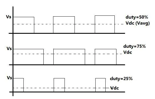
Pulse width modulation means varying the width (duty) of pulse. Width means ON time Ton of pulse. The average output voltage (Vdc or Vavg) is given by equation
Vdc = [Ton / (Ton+Toff)] × Vs
It directly depends upon Ton. As shown in above figure if duty is 50% the average output voltage Vdc is exactly the half of Vs. If duty is increased to 75%, Vdc also increases to 3/4th of Vs and if duty is decreased to 25%, Vdc reduces to 1/4th of Vs. Thus as pulse width varies the average output voltage varies. So we have to apply PWM to DC motor to vary its speed.
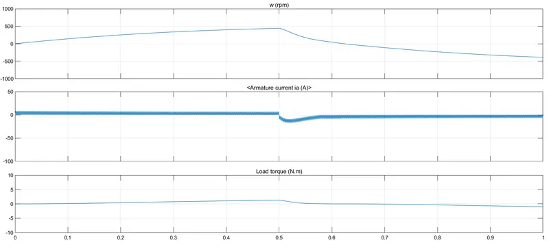
The motor starts positive direction with 75% duty cycle. At t=0.5sec armature voltage is suddenly reversed and the motor runs in negative direction.
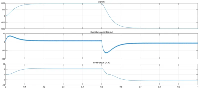
Pulse width 50%
1(C). Refer to the help section of ‘The Four-Quadrant Chopper DC Drive (DC7) block’. Compare it with the H-bridge model.
The Four-Quadrant Chopper DC Drive (DC7) block represents a four-quadrant, DC-supplied, chopper (or DC-DC PWM converter) drive for DC motors. This drive features closed-loop speed control with four-quadrant operation. The speed control loop outputs the reference armature current of the machine. Using a PI current controller, the chopper duty cycle corresponding to the commanded armature current is derived. This duty cycle is then compared with a sawtooth carrier signal to obtain the required PWM signals for the chopper.
The main advantage of this drive, compared with other DC drives, is that it can operate in all four quadrants (forward motoring, reverse regeneration, reverse motoring, and forward regeneration). In addition, due to the use of high switching frequency DC-DC converters, a lower armature current ripple (compared with thyristor-based DC drives) is obtained. However, four switching devices are required, which increases the complexity of the drive system.
The Four-Quadrant Chopper DC Drive block uses these blocks from the Electric Drives/Fundamental Drive Blocks library:
-
Speed Controller (DC)
-
Regulation Switch
-
Current Controller (DC)
-
Chopper
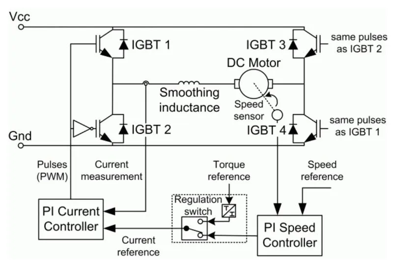
Comparision of Four quadrant chopper DC7 block vs H-bridge model:
1).Four quadrant choppers can operates in all four modes
H-bridge can operate only in two modes.
2). In four quadrant chopper regenerative braking is possible
In H-bridge regenerative braking is not possible.
3). Four quadrant choppers are widely used in Automobile
H-bridge are widely used in robotics
2. Develop a 2-quadrant chopper using simulink & explain the working of the same with the relevant results. (Refer to article - Multiquadrant operation of motor )
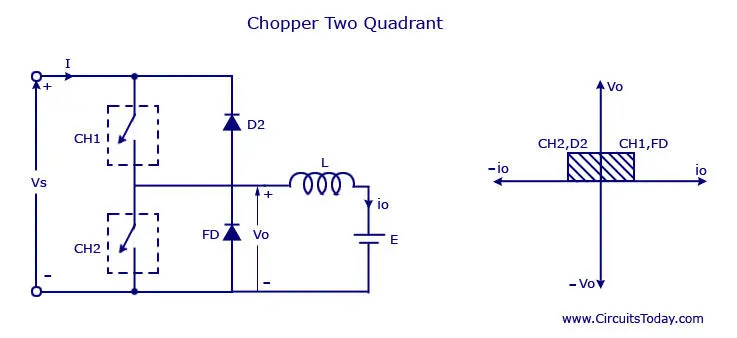
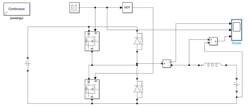
Block used in 2-quadrant chopper
- Powergui
- MOSFET
- Diode
- Current measurement
- Voltage measurement
- Pulse generator
- Series RLC branch
Powergui needed for simulation, without this block the simulation will not take place
Use of NOT operator is to ensure that both the switches does not conduct simultaneously, if they do so the supply will short circuit. if switch 1 conducts , switch 2 definitely will not conducts because we are using NOT gate.
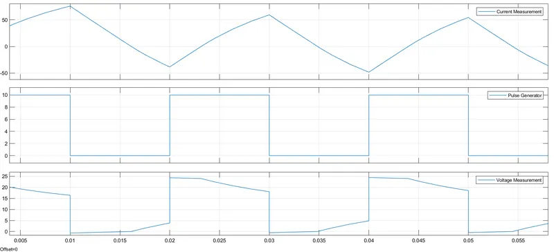
Output:
Current goes positive and negative based on the switching action, it increase and decrease consequently.
Voltage remains always positive.
3. Explain in a brief about operation of BLDC motor.
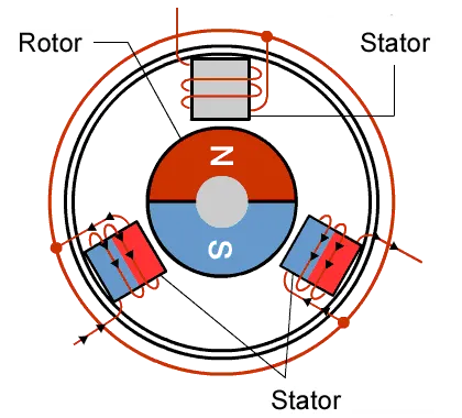
A brushless DC motor (also known as a BLDC motor or BL motor) is an electronically commuted DC Motor which does not have brushes. The controller provides pulses of current to the motor windings which Control the speed and torque of the synchronous motor
These types of motors are highly efficient in producing a large amount of torque over a vast speed range. In brushless motors, permanent magnets rotate around a fixed armature and overcome the problem of connecting current to the armature. Commutation with electronics has a large scope of capabilities and flexibility. They are known for smooth operation and holding torque when stationary.
In brushes motors, there are permanent magnets on the outside and a spinning armature which contains electromagnet is inside. These electromagnets create a Magnetic field in the armature when the power is switched on and help to rotate the armature.
The brushes change the polarity of the pole to keep the rotation on of the armature. The basic working principle for the brushed DC motor and for brushless DC motor are same i.e. internal shaft position feedback.
Brushless DC motor has only two basic parts: rotor and the stator. The rotor is the rotating part and has rotor magnets whereas stator is the stationary part and contains stator windings. In BLDC permanent magnets are attached in the rotor and move the electromagnets to the stator. The high power transistors are used to activate electromagnets for the shaft turns. The controller performs power distribution by using a solid-state circuit.
Types of Brushless DC Motors
Basically, BLDC are of two types, one is outer rotor motor and other is inner rotor motor. The basic difference between the two is only in designing, their working principles are same.
Inner Rotor Design
In an inner rotor design, the rotor is located in the centre of the motor and the stator winding surround the rotor. As the rotor is located in the core, rotor magnets do not insulate heat inside and heat get dissipated easily. Due to this reason, inner rotor designed motor produces a large amount of torque and validly used.
Outer Rotor Design
In outer rotor design, the rotor surrounds the winding which is located in the core of the motor. The magnets in the rotor trap the heat of the motor inside and do not allow to dissipate from the motor. Such type of designed motor operates at lower rated current and has low cogging torque.