Hybrid Electric Vehicle: DC Motor Simulation & Analysis
OBJECTIVE
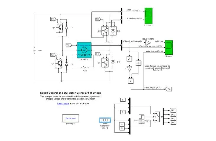
1. A. Explain a MATLAB demo model named ‘Speed control of a DC motor using BJT H-bridge’.
B. Comment on the armature current shoot-up from the scope results.
C. Refer to the help section of ‘The Four-Quadrant Chopper DC Drive (DC7) block’. Compare it with the H-bridge model.
2. Develop a 2-quadrant chopper using simulink & explain the working of the same with the relevant results. (Refer to article - Multiquadrant operation of motor )
3. Explain in a brief about operation of BLDC motor.
SOLUTION
1. A. Explain a MATLAB demo model named ‘Speed control of a DC motor using BJT H-bridge’.
The Bipolar Junction Transistor (BJT), are used for power switching applications, and are operated as an IGBT.
- When it is conducting (BJT operating in the saturated region), a forward voltage Vf is developed between collector and emitter (in the range of 1 V).
- Therefore, the IGBT block can be used to model the BJT device.
The H-bridge consists of four BJT/Diode pairs (BJT simulated by IGBT models).
- Two transistors are switched simultaneously: Q1 and Q4 or Q2 and Q3.
- When Q1 and Q4 are fired, a positive voltage is applied to the motor and diodes D2-D3 operate as free-wheeling diodes when Q1 and Q4 are switched off.
- When Q2 and Q3 are fired, a negative voltage is applied to the motor and diodes D1-D4 operate as free-wheeling diodes when Q2 and Q3 are switched off.
B. Comment on the armature current shoot-up from the scope results.
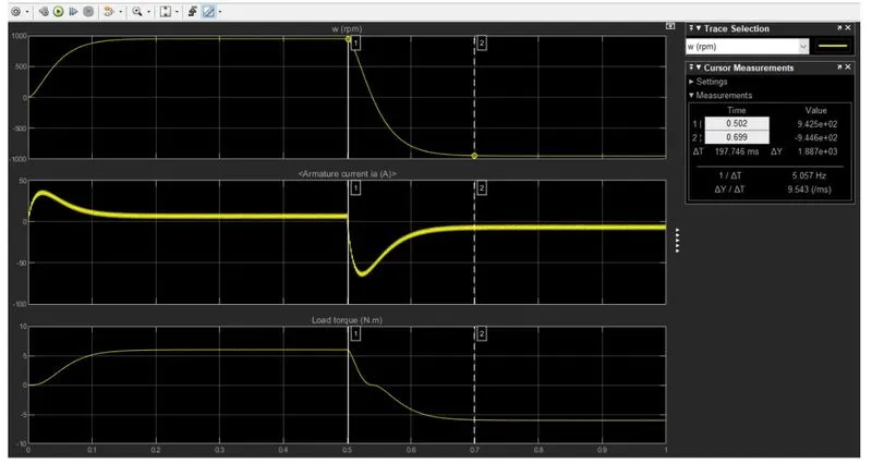
COMMENTS:
- The motor starts in a positive direction with a duty cycle of 75% (mean DC voltage of 180V).
- At t= 0.5 sec., the armature voltage is suddenly reversed and the motor runs in a negative direction.
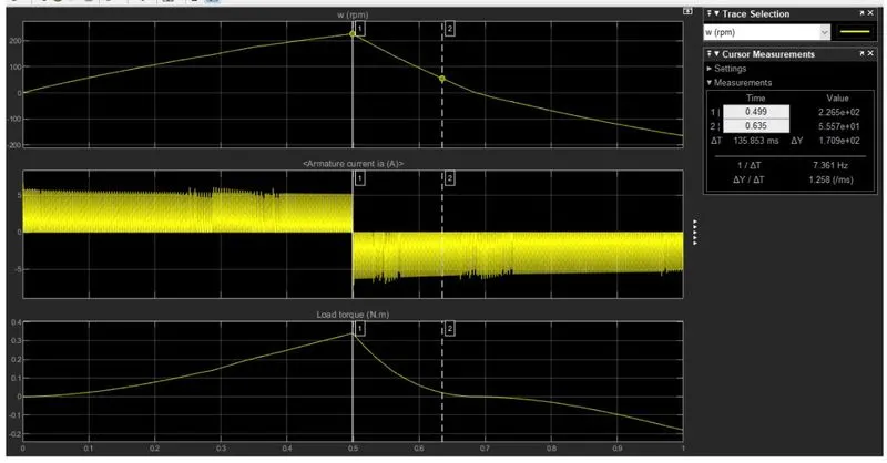
COMMENTS:
- 'Scope' shows motor speed, armature current, and load torque.
- 'Currents' shows currents flowing in BJT Q3 and diode D3.
C. Refer to the help section of ‘The Four-Quadrant Chopper DC Drive (DC7) block’. Compare it with the H-bridge model.
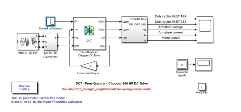
EXPLAINATION WITH REF. TO THE ABOVE CIRCUIT:
- The 200 HP DC motor is separately excited with a constant 150 V DC field voltage source.
- The armature voltage is provided by an IGBT converter controlled by two PI regulators.
- The converter is fed by a 515 V DC bus obtained by rectification of a 380 V AC 50 Hz voltage source.
- In order to limit the DC bus voltage during dynamic braking mode, a braking chopper has been added between the diode rectifier and the DC7 block.
- The first regulator is a speed regulator, followed by a current regulator.
- The speed regulator outputs the armature current reference (in p.u.) used by the current controller in order to obtain the electromagnetic torque needed to reach the desired speed.
- The speed reference change rate follows acceleration and deceleration ramps in order to avoid sudden reference changes that could cause armature over-current and destabilize the system.
- The current regulator controls the armature current by computing the appropriate duty ratios of the 5 kHz pulses of the four IGBT devices (Pulse Width Modulation).
- For proper system behaviour, the instantaneous pulse values of IGBT devices 1 and 4 are opposite to those of IGBT devices 2 and 3.
- This generates the average armature voltage needed to obtain the desired armature current.
- In order to limit the amplitude of the current oscillations, a smoothing inductance is placed in series with the armature circuit.
2. Develop a 2-quadrant chopper using simulink & explain the working of the same with the relevant results. (Refer to article - Multiquadrant operation of motor )
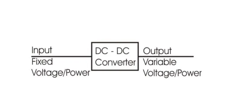
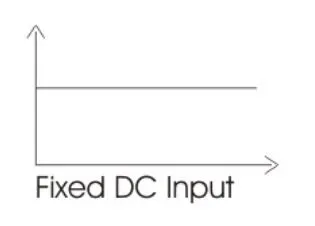
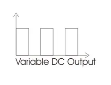
Chopper is a DC-DC converter circuit. It will convert a fixed DC into Variable DC.
H-BRIDGE
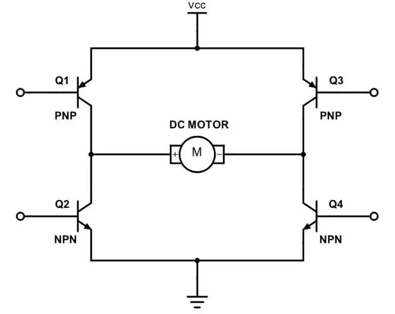
An H-bridge is a simple circuit that lets you control a DC motor to go backward or forward.
CIRCUIT DIAGRAM
WORKING
- If we close switch 1 and 4, you have plus connected to the left side of the motor and minus to the other side.
- And the motor will start spinning in one direction.
WORKING DIARAM: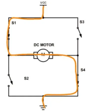
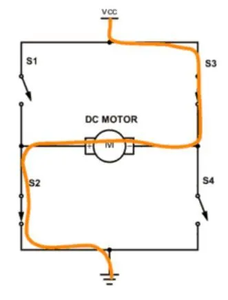
- If you instead close switch 2 and 3, you have plus connected to the right side and minus to the left side.
- And the motor spins in the opposite direction.
WORKING DIAGRAM:
3. Explain in a brief about operation of BLDC motor.
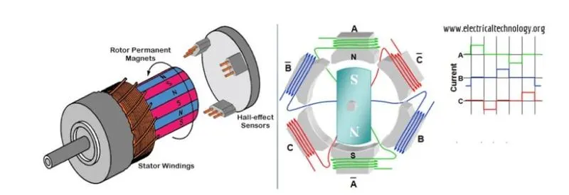
- BLDC motor works on the principle similar to that of a conventional DC motor, i.e., the Lorentz force law which states that whenever a current carrying conductor placed in a magnetic field it experiences a force.
- As a consequence of reaction force, the magnet will experience an equal and opposite force.
- In case BLDC motor, the current carrying conductor is stationary while the permanent magnet moves.
- When the stator coils are electrically switched by a supply source, it becomes electromagnet and starts producing the uniform field in the air gap.
- Though the source of supply is DC, switching makes to generate an AC voltage waveform with trapezoidal shape.
- Due to the force of interaction between electromagnet stator and permanent magnet rotor, the rotor continues to rotate.
- Consider the figure below in which motor stator is excited based on different switching states.
- With the switching of windings as High and Low signals, corresponding winding energized as North and South poles.
- The permanent magnet rotor with North and South poles align with stator poles causing motor to rotate.
- Observe that motor produces torque because of the development of attraction forces (when North-South or South-North alignment) and repulsion forces (when North-North or South-South alignment).
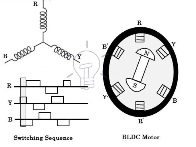
- By this way motor moves in a clockwise direction.
- Based on this signal from sensor, the controller decides particular coils to energize.
- Hall-effect sensors generate Low and High level signals whenever rotor poles pass near to it.
- These signals determine the position of the shaft.