Week-7 Challenge: DC Motor Control
- Run MATLAB demo ‘Speed control of a DC motor using BJT H-bridge’. Modify the model such that armature current doesn’t shoot up when motor changes direction from forward to reverse.
Description:
The Bipolar Junction Transistor (BJT) when used for power switching applications, operates as an IGBT. When it is conducting (BJT operating in the saturated region), a forward voltage Vf is developed between collector and emitter (in the range of 1 V). Therefore, the IGBT block can be used to model the BJT device.
The IGBT block does not simulate the gate current controlling the BJT or IGBT. The switch is controlled by a Simulink® signal (1/0). The DC motor uses the preset model (5 HP 24V 1750 rpm). It simulates a fan type load (where Load torque is proportional to square of speed). The armature mean voltage can be varied from 0 to 240 V when the duty cycle (specified in the Pulse Generator block) is varied from 0 to 100%.
The H-bridge consists of four BJT/Diode pairs (BJT simulated by IGBT models). Two transistors are switched simultaneously: Q1 and Q4 or Q2 and Q3. When Q1 and Q4 are fired, a positive voltage is applied to the motor and diodes D2-D3 operate as free-wheeling diodes when Q1 and Q4 are switched off. When Q2 and Q3 are fired, a negative voltage is applied to the motor and diodes D1-D4 operate as free-wheeling diodes when Q2 and Q3 are switched off.
H bridge: An H-bridge is a simple circuit that lets you control a DC motor to go backward or forward.
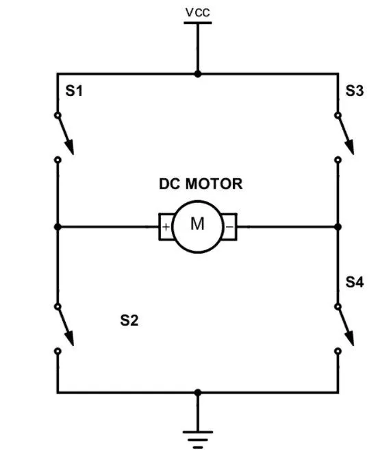
The above is the conceptual model of H bridge.
A DC motor spins either backward or forward, depending on how you connect the plus and the minus.
If you close switch 1 and 4, you have plus connected to the left side of the motor and minus to the other side. And the motor will start spinning in one direction.
What Is an H-Bridge?
By Øyvind Nydal Dahl 24 Comments
 An H-bridge is a simple circuit that lets you control a DC motor to go backward or forward.
You normally use it with a microcontroller, such as an Arduino, to control motors.
When you can control two motors to go either forward or backward – you can build yourself a robot!
H-Bridge concept
Here’s the concept of the H-bridge:
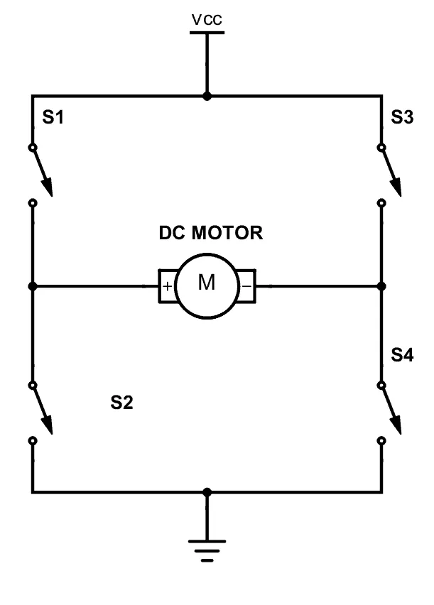
A DC motor spins either backward or forward, depending on how you connect the plus and the minus.
If you close switch 1 and 4, you have plus connected to the left side of the motor and minus to the other side. And the motor will start spinning in one direction.
If you instead close switch 2 and 3, you have plus connected to the right side and minus to the left side. And the motor spins in the opposite direction.
The matlab model for "Speed control of a DC motor using BJT H-bridge" is below
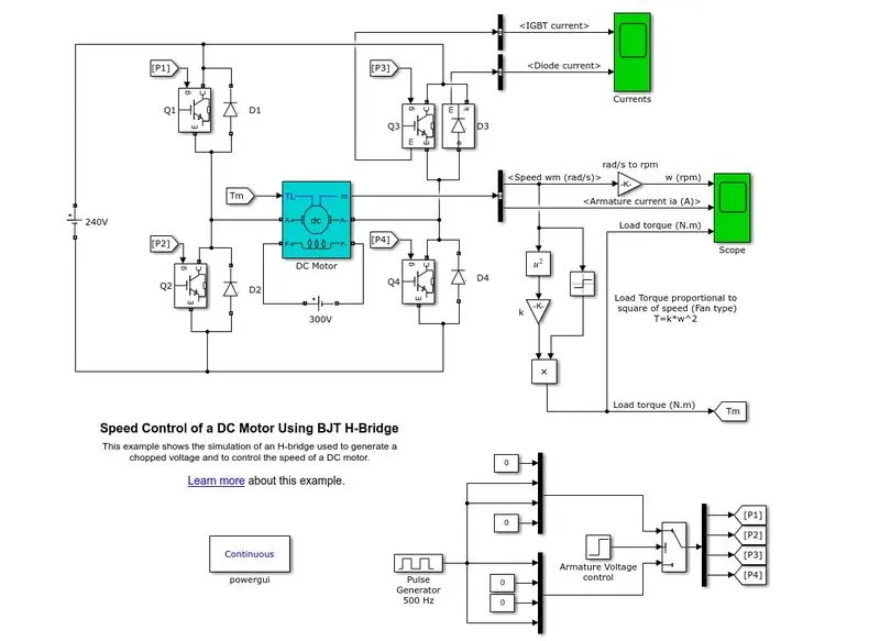
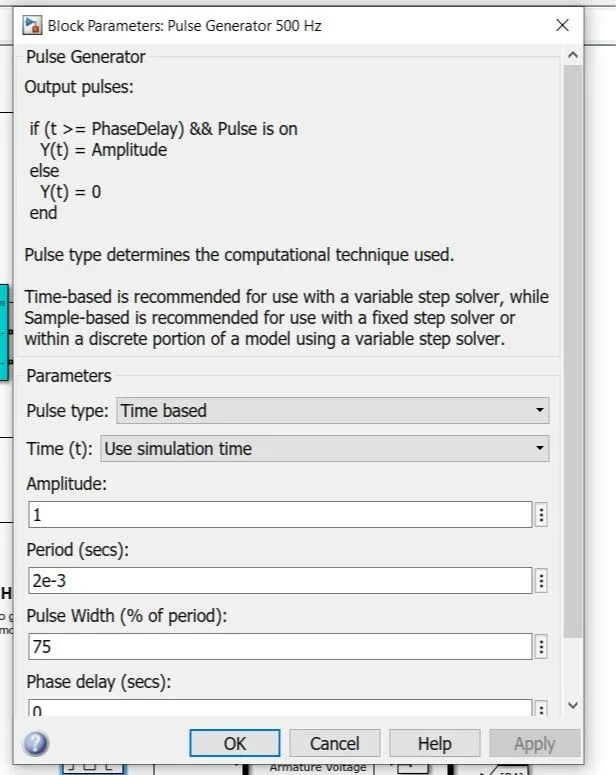
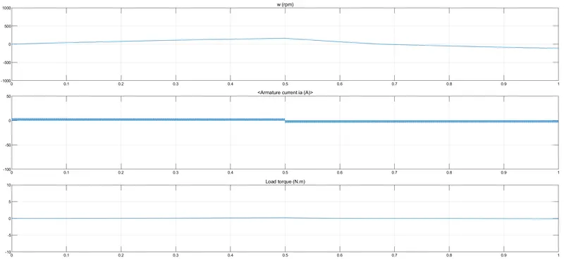
Here in above model the pulse genertor block is set to a Duty cycle of 75%.
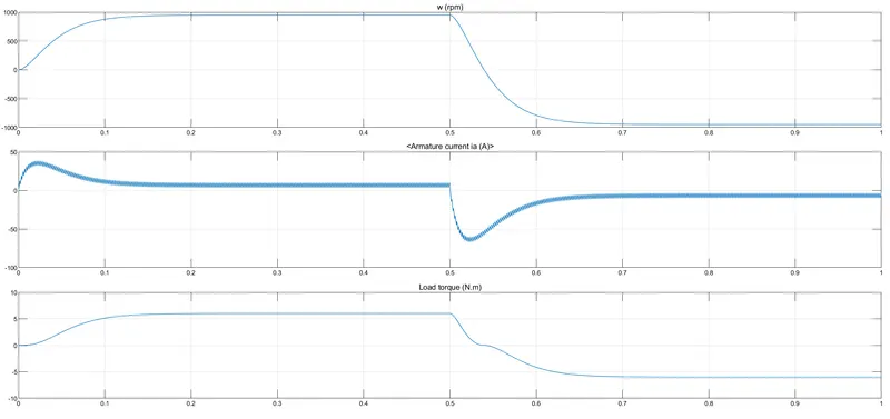
The step time being set to 0.5 i.e after 0.5 sec the motor will reverse the direction.
We observe that the armature current shoots up when the motor changes its direction of rotation.
Now we have to set the duty cycle in such a way that the current doesnot shoots up.
Setting the duty cycle to 30% we can almost control the shooting of armature current.
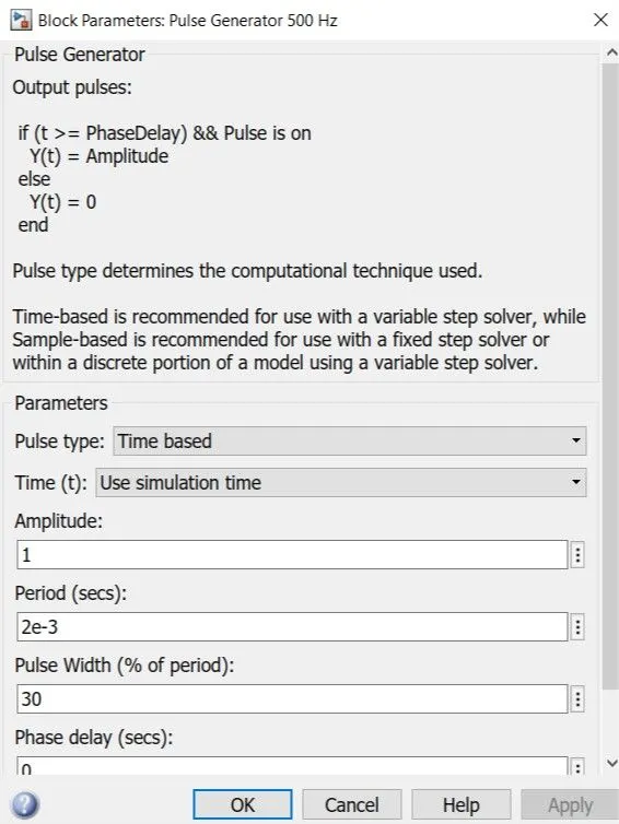
The decrease in Pulse width or Duty cycle results in constant current in armature which can be seen below.
2.Refer to help section of ‘The Four-Quadrant Chopper DC Drive (DC7) block’. Compare it with H-bridge model.
The 200 HP DC motor is separately excited with a constant 150 V DC field voltage source. The armature voltage is provided by an IGBT converter controlled by two PI regulators. The converter is fed by a 515 V DC bus obtained by rectification of a 380 V AC 50 Hz voltage source. In order to limit the DC bus voltage during dynamic braking mode, a braking chopper has been added between the diode rectifier and the DC7 block.
The first regulator is a speed regulator, followed by a current regulator. The speed regulator outputs the armature current reference (in p.u.) used by the current controller in order to obtain the electromagnetic torque needed to reach the desired speed. The speed reference change rate follows acceleration and deceleration ramps in order to avoid sudden reference changes that could cause armature over-current and destabilize the system.
Comparision between 'H bridge model' and 'Four quadrant chopper DC drive'
Four Quadrant DC Chopper
It can operate in all Four qudrants. The motor direction can be changed with change in polarity
Regenerative braking is possible. Because of speed reference change there is no sudden increase in armature current. It has higher efficiency.
H bridge model
The motor direction is controoled through switch control. Regenerative braking is not possible.
Due to sudden change in curent direction armature current is high. Its efficiency is low.
3. Make a suitable EV model using DC7 block and make result report.
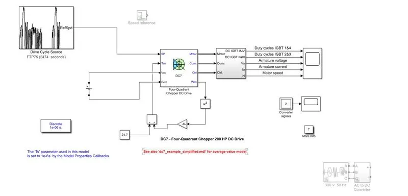
Description: The existing DC7 block is to be modeled as per EV requirements.
1) The speed reference may be replaced with another drive cycle.
2) The appropriate DC voltage source (which signifies battery of EV) can be taken in place of AC to DC converter.
3) Linear torque load block is replaced with a charaterstic equation of DC motor for linear torque speed character.
i.e `T=24.7+0.0051*omega^2`
Suitable blocks have been used in connection to imply the torque equation. (square block,constant block,gain block) in place of linear torque load block.
The simultaion time is set to 10 seconds.
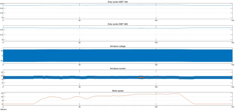
Thus we can obsersve that the duty cycle for both the cases is almost set to 50%.
The armature current is smoother because of new torque speed equation.
4. Explain in a brief about operation of BLDC motor.
Description:
Brushless DC motors are common in industrial applications across the world. At the most basic level, there are brushed and brushless motors and there are DC and AC motors. Brushless DC motors, as you may imagine, do not contain brushes and use a DC current.
These motors provide many specific advantages over other types of electrical motors, but, going beyond the basics, what exactly is a brushless DC motor? How does it work and what’s it used for?
How a Brushless DC Motor Works
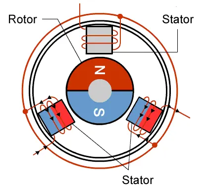
It often helps to explain how a brushed DC motor works first, as they were used for some time before brushless DC motors were available. A brushed DC motor has permanent magnets on the outside of its structure, with a spinning armature on the inside. The permanent magnets, which are stationary on the outside, are called the stator. The armature, which rotates and contains an electromagnet, is called the rotor.
In a brushed DC motor, the rotor spins 180-degrees when an electric current is run to the armature. To go any further, the poles of the electromagnet must flip. The brushes, as the rotor spins, make contact with the stator, flipping the magnetic field and allowing the rotor to spin a full 360-degrees.
A brushless DC motor is essentially flipped inside out, eliminating the need for brushes to flip the electromagnetic field. In brushless DC motors, the permanent magnets are on the rotor, and the electromagnets are on the stator. A computer then charges the electromagnets in the stator to rotate the rotor a full 360-degrees.