Week - 4
Objective:
- Implement control logic of a “washing machine” using Stateflow as per given sequence:
- If the power supply is available, the system gets activated
- If the Water supply is not available, stop the process & indicate through LED
- Soaking time should be 200s followed by Washing time of 100s.
- Then rinsing happens for next 20s & dryer runs for 50s
After all the processes have completed turn on the finished LED
Description:
The control logic as per given objective is below:
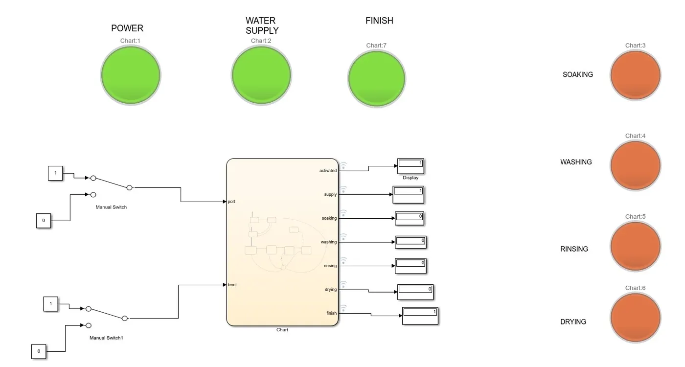
State flow Chart:
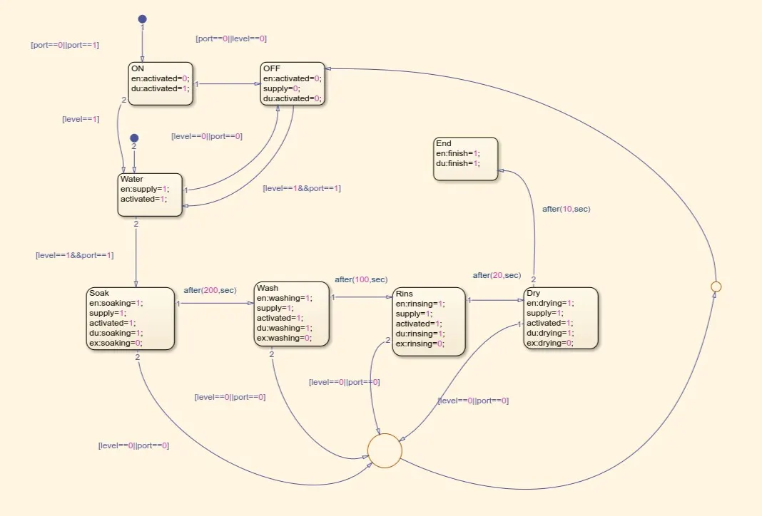
Power (ON) supply & Water are two default transition state.
Manual switch has been used for connecting to both water supply (level) & Power supply (Port).
Lamp has been used for each of the state which goes green when the logic is true & red when the logic is false.
The state actions entry, during & exit has been used accordingly to implement desired logic.
Temporal logic 'after' has been used for transition from one state to another after a certain fixed time interval.
logic ' OR' || , 'AND' && had been used to.
1. When the power switch is turned on it checks for water supply using following loop.
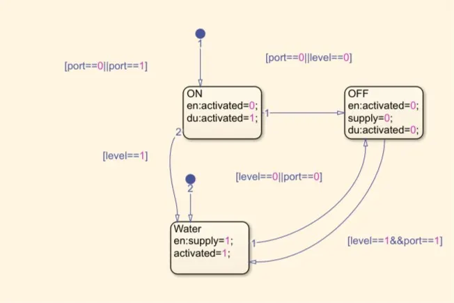
If power is on & water supply is 1(on). Then, all other states will be executed sequentially(i.e soaking,washing,rinsing etc.) else it will turn off.
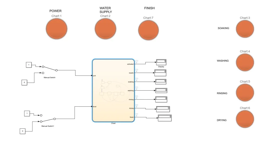
Below is the image attached for the case when power is on and supply is low (i.e 0). We can obsereve that as soon as the supply is checked to be low the machine goes to OFF state and hence all lamps are red color.
Objective 2:
Make a Simulink chart for the “Gear shift” logic as per below conditions:
Speed Range(kmph) Gear
0 to 15 1
16 to 25 2
26 to 40 3
41 to 60 4
Above 61 5
Give speed input while the simulation is running & display the gear number.
Description: The simulink logic & state flow chart for above logic is below:
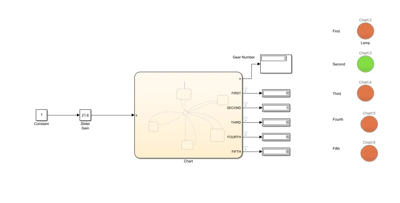
Chart:
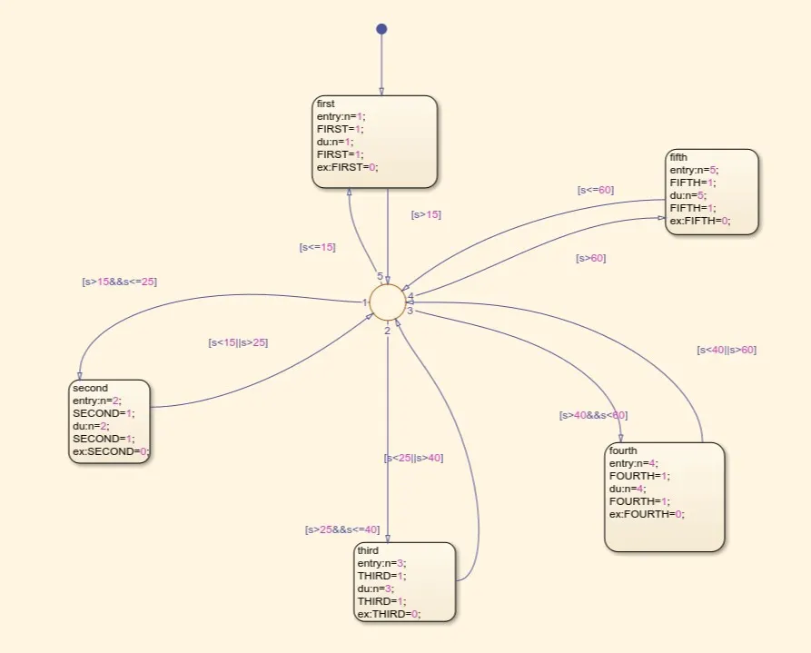
For replicating accelarator 'Slider gain block 'has been used with lower & upper limit 0 & 120.
Default transition is for First gear.
Display block is there for displaying current state (i.e current state).
'n' is the Gear number that is engaged at any given time.
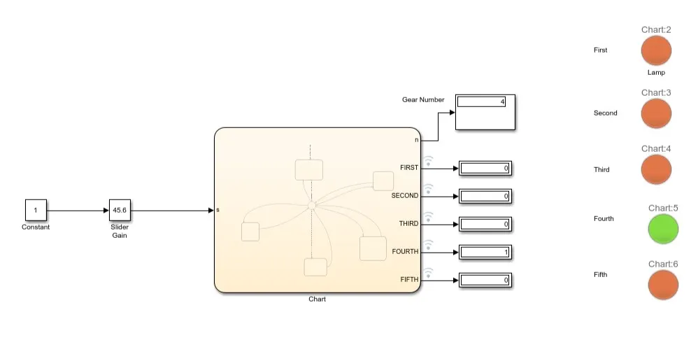
When speed is in range of 26-40. The engaged gear is 4 which is correct as per given objective.
Let us take a case from transition of state from first to second to another.
When speed is in range of 0-15. state 1 is active. When the condition for speed greater than equal to 16 and less than equal to 25 is true then second gear is engaged. Then if either of the condition i.e speed is less than 16 or greater than 25 then the state will change from 2 to another accordingly.
Note: The slx file for both the given objective have been attached.
https://drive.google.com/drive/folders/1xQusQUo5i-cnPKUgu0sY_AwQaEXeBuKd?usp=sharing