Week-7 Challenge: DC Motor Control
1.Run MATLAB demo ‘Speed control of a DC motor using BJT H-bridge’. Modify the model such that the armature current doesn’t shoot up when the motor changes direction from forward to reverse.
BJT H-bridge:
The Bipolar Junction Transistor (BJT) when used for power switching applications, operates as an IGBT. When it is conducting (BJT operating in the saturated region), a forward voltage Vf is developed between collector and emitter (in the range of 1 V). Therefore, the IGBT block can be used to model the BJT device.
The IGBT block does not simulate the gate current controlling the BJT or IGBT. The switch is controlled by a Simulink® signal (1/0). The DC motor uses the preset model (5 HP 24V 1750 rpm). It simulates a fan type load (where Load torque is proportional to the square of speed). The armature mean-voltage can be varied from 0 to 240 V when the duty cycle (specified in the Pulse Generator block) is varied from 0 to 100%.
H-bridge schematic:
Simulink model: Speed control of a DC motor using BJT H-bridge
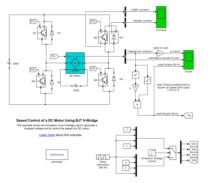
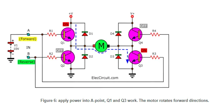
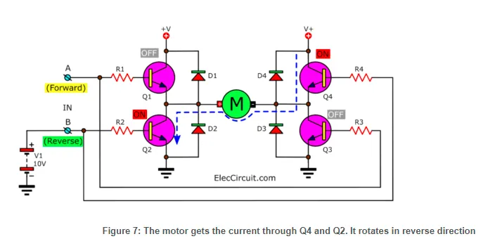
The H-bridge consists of four BJT/Diode pairs (BJT simulated by IGBT models). Two transistors are switched simultaneously: Q1 and Q4 or Q2 and Q3. When Q1 and Q4 are fired, a positive voltage is applied to the motor, and diodes D2-D3 operate as free-wheeling diodes when Q1 and Q4 are switched off. When Q2 and Q3 are fired, a negative voltage is applied to the motor, and diodes D1-D4 operate as free-wheeling diodes when Q2 and Q3 are switched off.
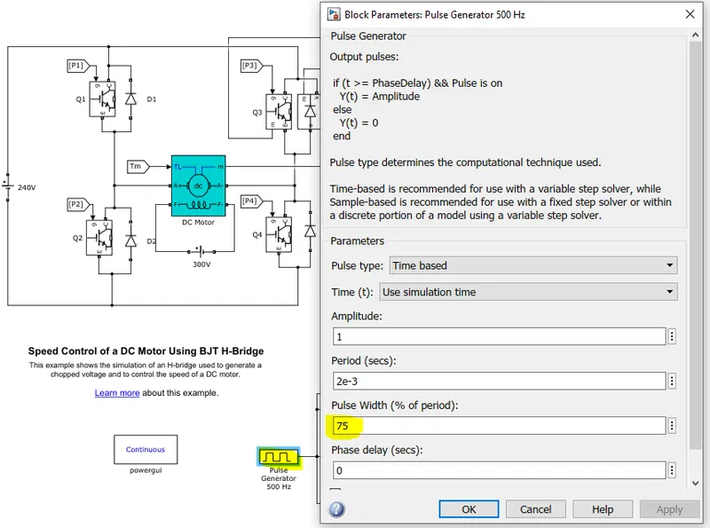
The pulse generator is used to control the duty cycle. The pulse width field allows us to modify the duty cycle of the motor and hence, we can prevent the motor current from shooting up when the motor changes its direction from forward to reverse. By default, the duty cycle is 75% meaning that the voltage is supplied to the motor for 75% of the time for one cycle. For the remaining 25%, the motor is off and receives no voltage from the source. It is this alternation between theON and OFF states, that allows us to vary the voltage that is supplied to the motor and thereby control the speed of an electric vehicle.
the output of the scope when the simulation is run using the preset values in the pulse generator block is shown below. There are 3 output graphs of angular speed, armature current, and the load torque all against a time axis.
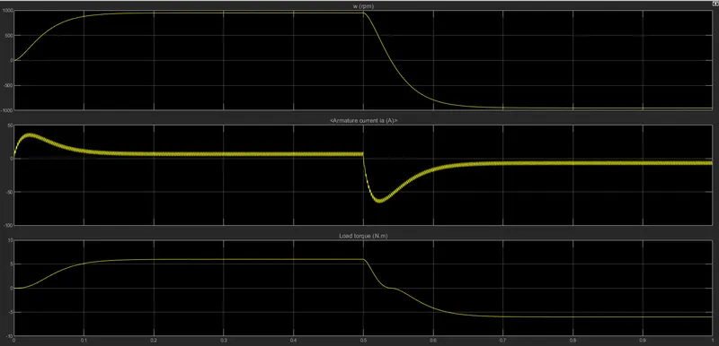
To modifying the simulation in order to prevent the initial shoot-up of the armature current at the start of the cycle. This sudden increase occurs whenever the armature voltage reverses direction
If we change the duty cycle i.e. the pulse width, we can control this initial shoot up of the current that occurs every time the armature voltage direction is reversed. When the duty cycle is decreased to 50% we can see that armature current does not shoot up initially for the positive direction of the armature voltage. However, when the armature voltage is reversed, the armature current shoots up in the negative direction.
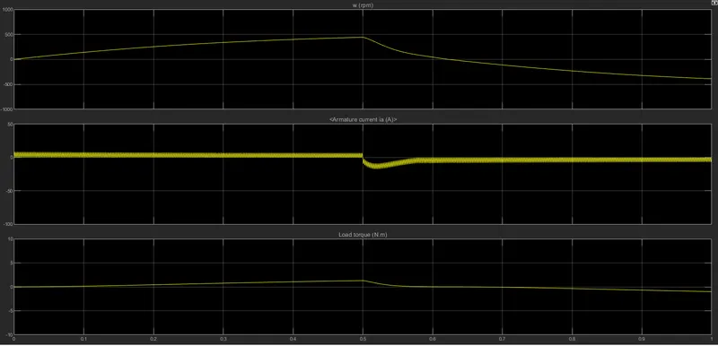
So, we need to decrease the duty cycle further to prevent this.
This time, I have reduced the duty cycle to 45%.
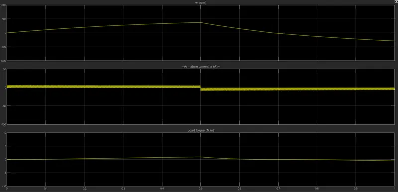
Here, we can see that at the start of the cycle in the positive armature voltage direction, the armature current does not shoot up as it did before. The armature current increases immediately to approximately 7A and it maintains that level until the next cycle where the armature voltage is reversed to -7A.
--------------------------------------------------------------------------------------------------------------------------------------------
2.Refer to the help section of ‘The Four-Quadrant Chopper DC Drive (DC7) block’. Compare it with the H-bridge model.
The four-quadrant chopper DC drive block in MATLAB/SIMULINK represents a four-quadrant, DC supplied chopper drive for DCmotors. It features closed-loop speed control with a four-quadrant operation. The closed-loop speed control will output the armature current of the machine. Using a PI current controller, the chopper duty cycle corresponding to the commanded armature current is derived. The duty cycle is then compared with a sawtooth carrier signal to obtain the required PWM signals for the chopper.
Compared to other DC drives, the main advantage of using the four-quadrant chopper DC drive is that it can operate in all 4quadrants. Each quadrant in its characteristics represents a different mode of operation as shown below
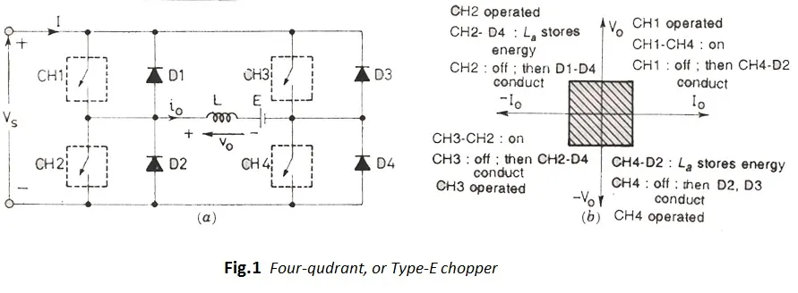
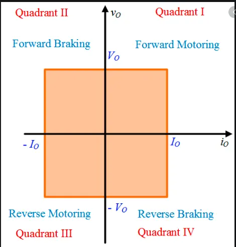
The Four-Quadrant Chopper vs H-bridge model.
H-Bridges like the 4 quadrant choppers are also capable of the braking operation without using air resistance or friction or physical brakes to bring the motor to rest. 4quadrant DC choppers are more commonly used in automobiles whereas BJT H-bridges are commonly used in robotics and electromechanical devices.
Unlike 4 quadrant DC choppers, BJT H-bridges are not capable of performing regenerative braking but they can perform dynamic braking. It is this difference that makes 4 quadrant DC choppers useful in hybrid and electric vehicles.
In 4 quadrant DC choppers, the current signals are interrupted with one another to change the direction of rotation of the motor. This is done by a speed reference or a drive cycle from which the speed values are converted to current signals which interrupt one another to change the rotation of the direction of the motor. However, in BJT H-bridges, the polarity of the current is reversed (depending on the duty cycle) to change the direction of rotation of the motor.
Also, the current signals in 4 quadrant DC choppers are chopped meaning that they are not continuous, they are discrete and take less time for simulations. But in BJT H-bridges, the current values are not chopped, meaning that they are continuous and so take more time for simulations.
Finally, in 4 quadrant DC choppers, a PI controller is used to control the speed and the current, and in the H-bridge, this is not implemented.
--------------------------------------------------------------------------------------------------------------------------------------------
3.Make a suitable EV model using DC7 block and make result report
Description
The 200 HP DC motor is separately excited with a constant 150 V DC field voltage source. The armature voltage is provided by an IGBT converter controlled by two PI regulators. The converter is fed by a 515 V DC bus obtained by rectification of a 380 V AC 50 Hz voltage source. In order to limit the DC bus voltage during dynamic braking mode, a braking chopper has been added between the diode rectifier and the DC7 block.
The first regulator is a speed regulator, followed by a current regulator. The speed regulator outputs the armature current reference (in p.u.) used by the current controller in order to obtain the electromagnetic torque needed to reach the desired speed. The speed reference change rate follows acceleration and deceleration ramps in order to avoid sudden reference changes that could cause armature over-current and destabilize the system. The current regulator controls the armature current by computing the appropriate duty ratios of the 5 kHz pulses of the four IGBT devices (Pulse Width Modulation). For proper system behavior, the instantaneous pulse values of IGBT devices 1 and 4 are opposite to those of IGBT devices 2 and 3. This generates the average armature voltage needed to obtain the desired armature current. In order to limit the amplitude of the current oscillations, a smoothing inductance is placed in series with the armature circuit.
EV model:
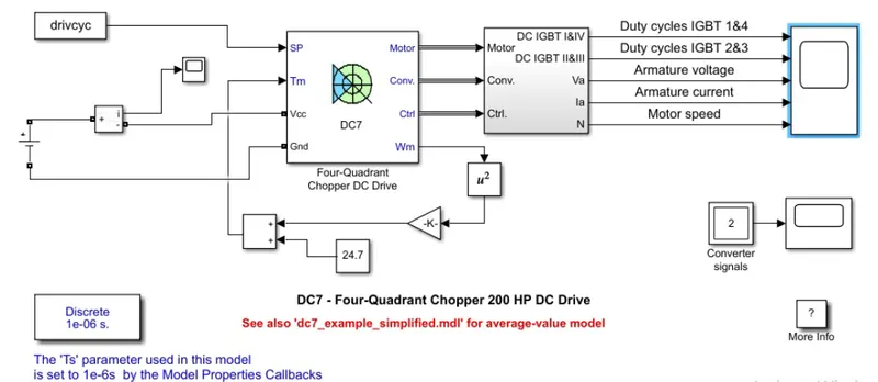
- a simple DC source is used as your energy source for the EV and the appropriate voltage value for an EV is given
- For this model of the EV, linear load torque block is replaced by a new equation that characterizes the relation between the torque and the speed which is shown below:`T_m=0.0051w^2+24.7`
where:
`w`-angular speed of the motor (radians per second)
`T_m`-Torque of the motor (Nm) - Nm - The current measurement block is used to find the input current from the source.
- Finally, a sample drive cycle is inserted from the workspace. This drive cycle has a duration of 10 seconds with time and velocity in the first and second columns respectively.
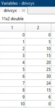
Result:
simulation is done for 10 seconds and the result is as follows
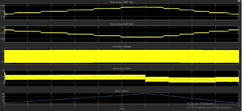
- Initially, there is a spike in the duty of IGBT switches 1&4 because the system is adjusting itself to provide the correct voltage to operate the motor
- When the motor angular speed increases, the duty cycle will also increase so that the average voltage that is supplied to the motor will be more. When the motor angular speed decreases, the duty cycle will also decrease so that the average voltage that is supplied to the motor will be lesser.
- The duty cycle of IGBT switches 2 and 3 decreases in pulses as the motor angular speed increases. The decrease in this duty cycle is corresponding to the increase in the duty cycle of IGBT 1&4
- the armature current fluctuations occur very rapidly as the IGBT switches 1&4 get switched ON and OFF continuously at a very high frequency
- till 6 seconds, the vehicle is in motoring mode after that there is braking which can be seen from the motor speed graph.