Week 7 Challenge - Assembly Workbench
Quick return mechanism:
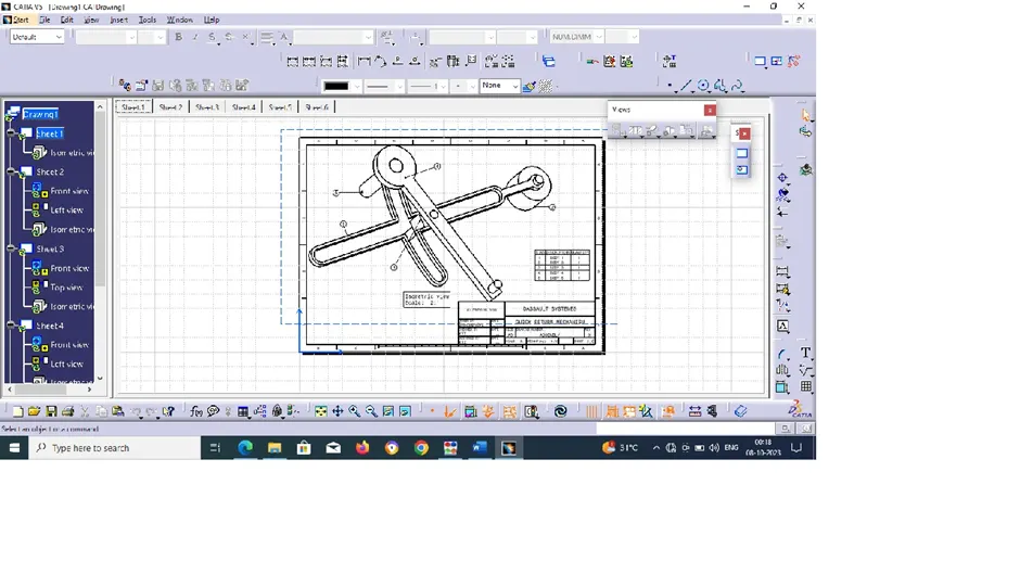
A quick return mechanism is an apparatus to produce a reciprocating motion in which the time taken for travel in return stroke is less than in the forward stroke. It is driven by a circular motion source (typically a motor of some sort) and uses a system of links with three turning pairs and a sliding pair. Quick return is a common feature of tools in which the action is performed in only one direction of the stroke, such as shapers and powered saws, because it allows less time to be spent on returning the tool to its initial position.
A quick return mechanism is a mechanism which produces a reciprocal effect so that the system takes less time in the return stroke while comparing with forward stroke. In the quick-return mechanism, a circular movement like the crank and lever mechanism is converted into reciprocal movement but the return time is different from the forward moment. In several applications, this process is used. Some of them are shaper, slotter, screw-press, mechanical drive, etc. The time required for cutting is reduced with the assistance of a quick return mechanism.
Quick return mechanism parts:
For the given quick return mechanism there are 5 parts. They are,
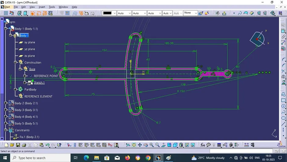
<!-- [if !supportLists]-->o <!--[endif]-->Slotted link
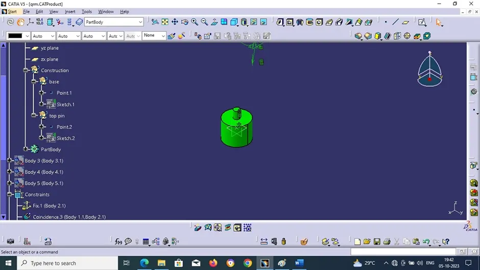
<!-- [if !supportLists]-->o <!--[endif]-->Pivot block
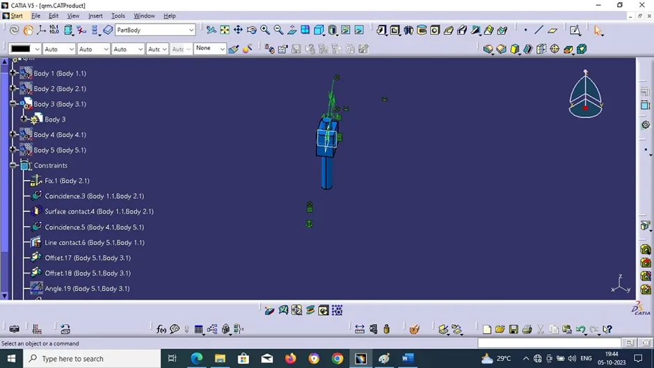
<!-- [if !supportLists]-->o <!--[endif]-->Sliding block
<!-- [if !supportLists]-->o <!--[endif]-->Crank
Part creation for the Quick return mechanism:
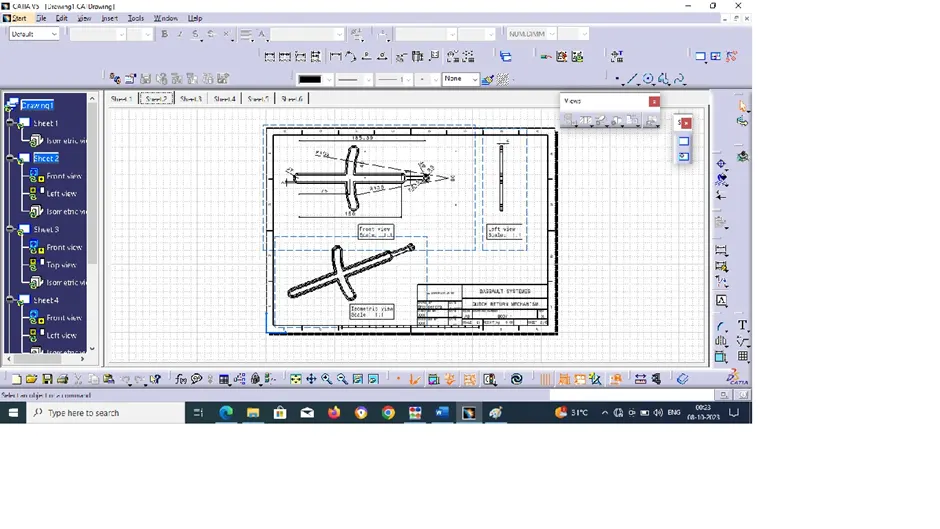
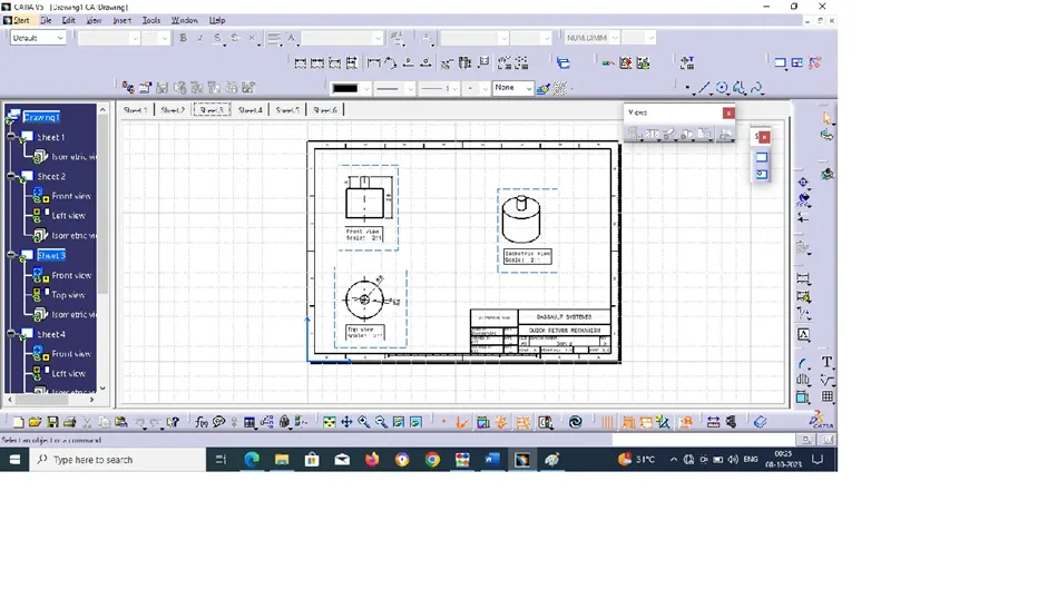
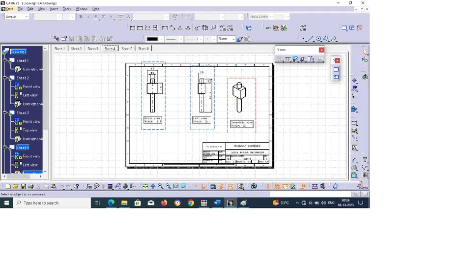
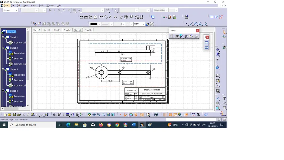
The following steps are involved in part creation for the quick return mechanism, The positioned sketches are created under the construction elements with iso-constrained geometry in the sketcher workbench with reference to the given sheets. These sketches are created in the appropriate planes to create solid parts. With help of those sketches solid parts are created using the pad command in the part work bench along the required direction. Then the parts are added and removed with help of Boolean operations according to the requirements
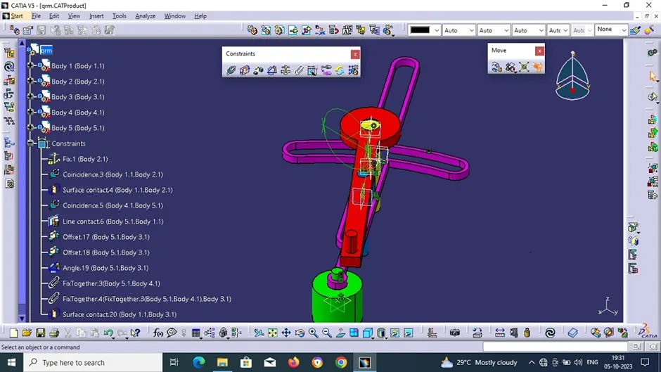
SLOTTED LINK
PIVOT BLOCK
SLIDING BLOCK
CRANK
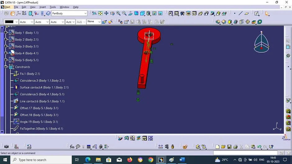
PIN
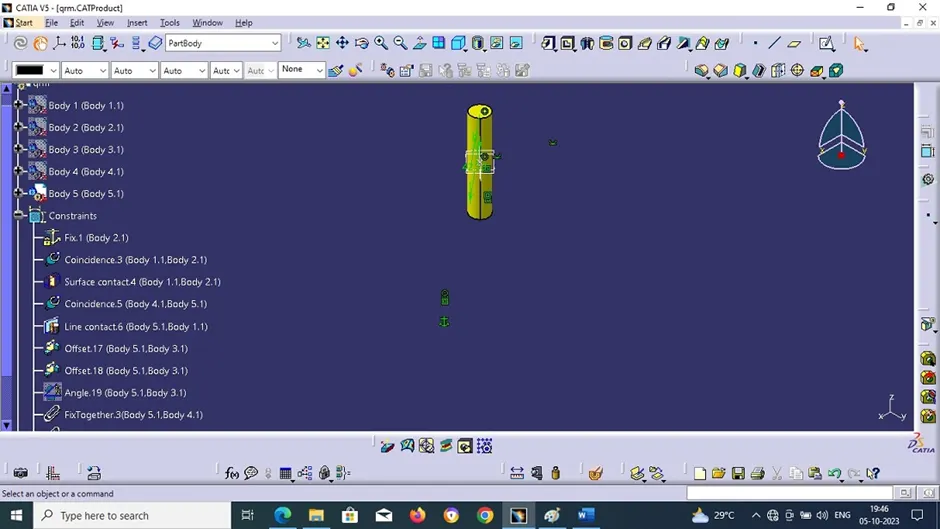
TREE
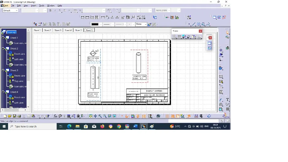
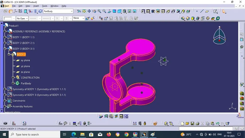
CV joint:
Constant-velocity joints (also known as homokinetic or CV joints) are mechanical joints which allow a drive shaft to transmit power through a variable angle, at constant rotational speed, without an appreciable increase in friction or play. They are mainly used in front-wheel drive vehicles. Modern rear-wheel drive cars with independent rear suspension typically use CV joints at the ends of the rear axle half shafts and increasingly use them on the drive shaft.
All front-wheel drive cars have Constant Velocity joints or CV joints on both ends of the drive shafts (half shafts). Inner CV joints connect the drive shafts to the transmission, while the outer CV joints connect the drive shafts to the wheels. Many rear-wheel drive and four-wheel drive cars as well as trucks also have CV joints.
The CV joints are needed to transfer the torque from the transmission to the drive wheels at a constant speed, while accommodating the up-and-down motion of the suspension. In front-wheel drive cars, CV joints deliver the torque to the front wheels during turns. There are two most commonly used types of CV joints: a ball-type and a tripod-type. In frontwheel drive cars, ball-type CV joints are used on the outer side of the drive shafts (outer CV joints), while the tripod-type CV joints are mostly used on the inner side (inner CV joints).
CV joint parts:
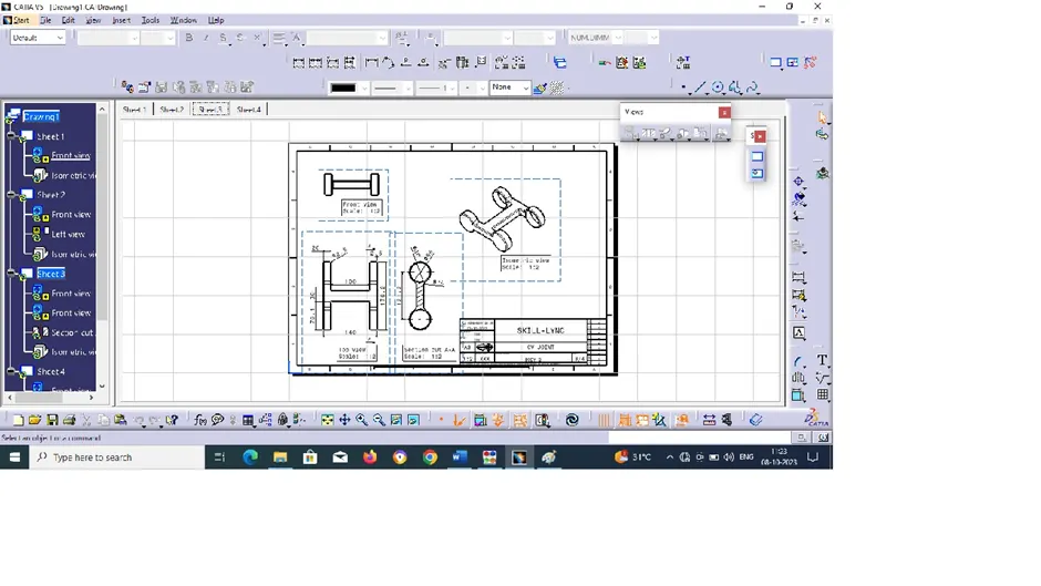
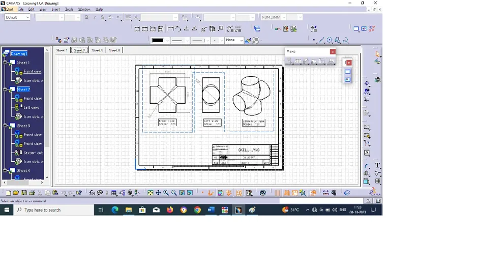
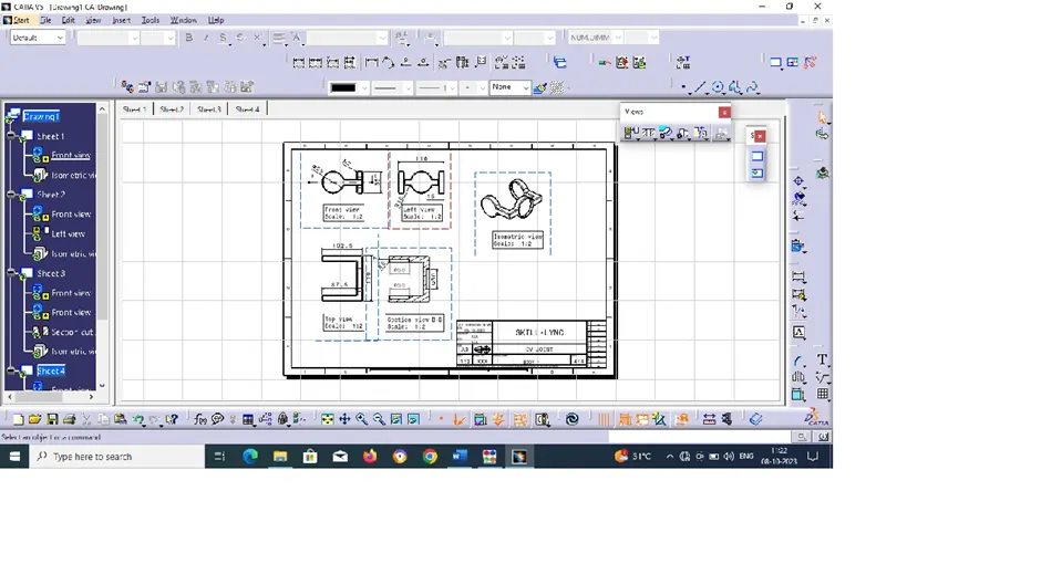
For the given cv joint there are 3 parts. They are,
<!-- [if !supportLists]-->o <!--[endif]-->Vertical holding cups
<!-- [if !supportLists]-->o <!--[endif]-->Centre shafts
<!-- [if !supportLists]-->o <!--[endif]-->Horizontal C cups.
Part creation for the CV joint:
The following steps are involved in part creation for the CV joint, The positioned sketches are created under the construction elements with iso-constrained geometry in the sketcher workbench with reference to the given sheets. These sketches are created in the appropriate planes to create solid parts. With help of those sketches solid parts are created using the pad command in the part work bench along the required direction. Then the parts are added and removed with help of Boolean operations according to the requirements.
Assembly:
The following steps are involved in the assembly of parts created before to form an CV joint. The assembly process is carried out in the assembly work bench and the assembly file has CAT Product as its extension. The assembly of CV joint starts with reference to the reference elements created in the part level. In part level the reference points, axis and planes are published to ease of access in the assembly work bench. Those publications are child features, if the parent features are modified in the part level its publications also get modified. Previously created parts are opened in the assembly work bench as child features of product, then a new part is created to serve as an assembly reference. This assembly reference is fixed to arrest it’s all degrees of freedom to hold the parts together. After the fixation, the parts are assembled with giving the coincident and offset relations to the appropriate planes, axis and points
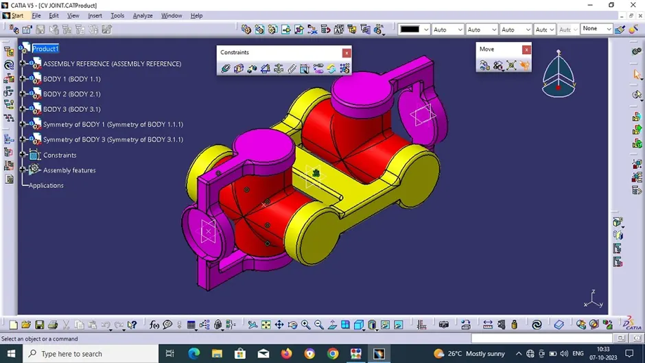
CENTRE SHAFT
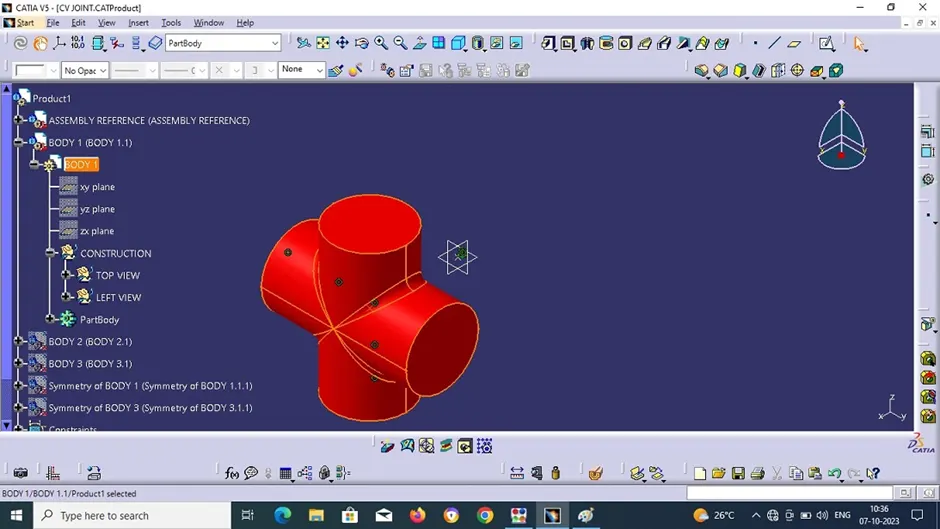
VERTICAL HOLDING CUP
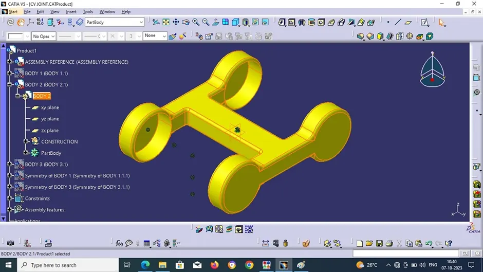
HORIZENTAL C CUP
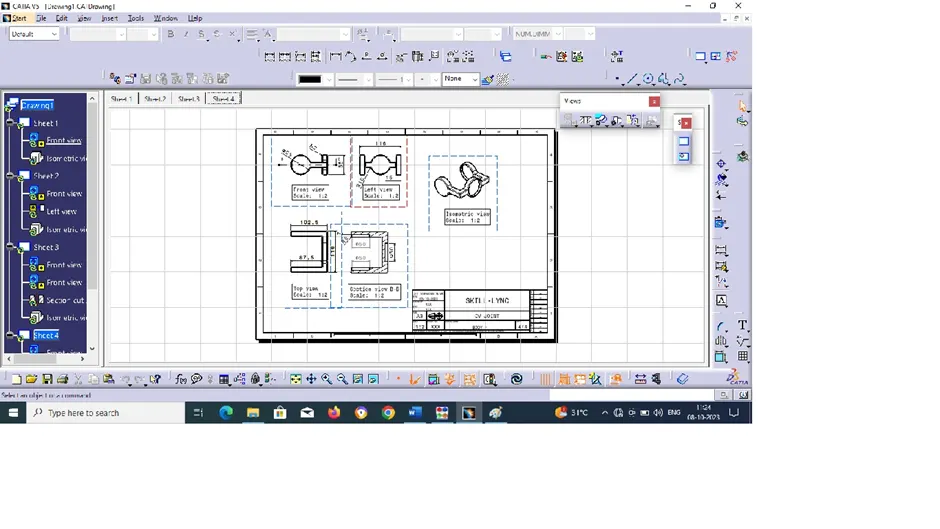
PROCEDURE:
1)First create all the parts of QUICK RETURN MECHANISM as well as of CV JOINT.
2)Create all the parts separately in the part work bench or generative work bench.
3)First create the sketch of the part in sketching work bench and make sure that the sketch is Iso constraint.
4)Then pad that sketch using pad feature in part work bench or extrude and trim accordingly in generative work bench.
5)Use Boolean operations and add or remove to obtain the required output.
6)While creating the parts in generative work bench make sure that you close surface the part you created.
7)Create all the parts and save the CAT. Part of all the parts that you have created separately. comment Share Project
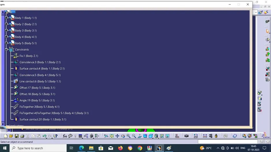
8)Then go to the assembly work bench and open the all the parts that you created using “open existing component” feature.
9)Then assemble them accordingly using the constraint tool box and move the parts in various directions as you need using move tool bar.