Week 7 Challenge
AIM: Modelling of Structure in STAAD Pro
INTRODUCTION:
STAAD.Pro is one of the most widely used structural analysis and design software products worldwide. It can apply more than 90 international steel, concrete, timber and aluminium design codes.
It can make use of various forms of analysis from the traditional static analysis to more recent analysis methods like p delta`Pushover analysis (Static-Non Linear Analysis) or a buckling analysis. It can also make use of various forms of dynamic analysis methods from time history analysis to response spectrum analysis. The response spectrum analysis feature is supported for both user defined spectra as well as a number of international code specified spectra.
Additionally, STAAD.Pro is interoperable with applications such as RAM Connection, AutoPIPE, SACS and many more engineering design and analysis applications to further improve collaboration between the different disciplines involved in a project. STAAD can be used for analysis and design of all types of structural projects from plants, buildings, and bridges to towers, tunnels, metro stations, water/wastewater treatment plants and more.
PROCEDURE:
STEP 1:
- Open the staad pro software.
- Go to file option click setting ...> click on display option to change the units..> click on structure unit option to change the units
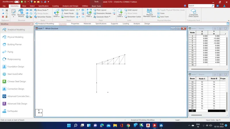
- open geometry add nodes
- 1st node be 0,0,0
- second node be at the distance of 15m
- copy the 1st node and paste it at -15m direction as shown below as per given data above.
- mid post height is 5m
- join the nodes by selecting option " add beam"
- similarly insert nodes in between the 1st and 15m node as shown by clicking insert node in the ribbon tab
- join all the nodes as shown.
- insert a node from the bottom of the column upto the distance of 5m'.
STEP 2:
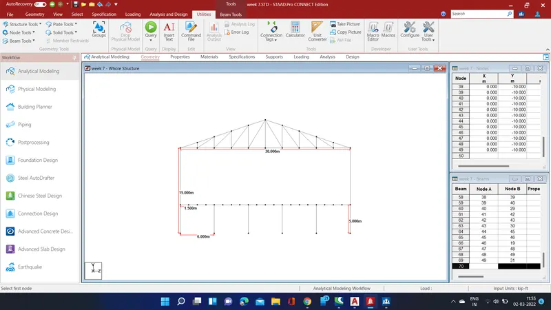
- CO[Y the structure on the left side and click on mirror option which is in the ribbon tab.
- the whole structure will be appeared as shown
- then join the node by selecting add beam option at the height of 5m where nodes present.
- click the beam and insert 4 nodes at the distance of 6m as shown
- then in the same manner copy and paste the node opposite below the nodes and connect the nodes by the means od add beam
- in between the columns created few nodes are to be created as per the diagram in the problem given
STEP 3:
- ONCE the geometry is done
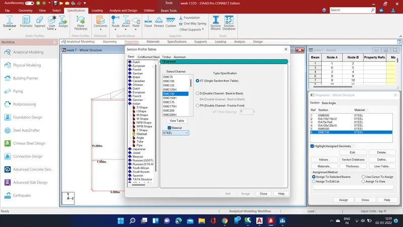
- go to properties option above the user interface
- we have add all the specifications and properties given:
- Columns - ISMB 500
- Truss -Top & Bottom chord – ISA 110x110x12, Diagonal member – ISA 75x75x8
- Purlins – ISMC 150
- Tie Beam – ISA 120x120x10
- Floor Primary beams – ISMB 300
- Secondary beams - ISMC 150
- Floor beam supporting columns – ISMB 300
- Assume bottom of the main column as Fixed support & intermediate floor beam supporting column as pinned
- Orient the Angle sections by applying Beta angle
open section data base option ....> indian...> select as per the requirement given and assign those properties to the beams and columns which was designed.
STEP 4:
- GO to utilites tab
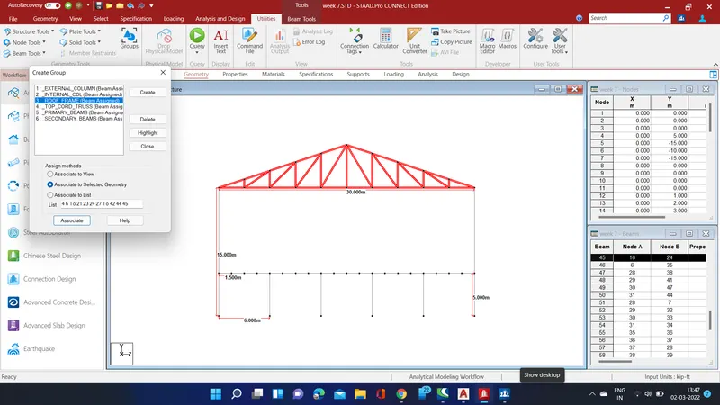
- you find a option called groups which we have to create and the assining of properties and specificaton will be easy through this method.
- open the group option you will find a window pop up showing create group, where we have to name the group required as
- External column
- Internal columns
- Roof Frames
- Top chord of the Truss
- Primary Beams
- Secondary Beams
there will be a option below the name that should be changed to beam
- once the group is done then if you want to know whether the group is created or not.
- click on the name which u have named and click highlight option , then the design is highlighted
STEP 5:
- THE material which is used to design the truss is steel.
- here we can see the all the materials are of steel

step 5:
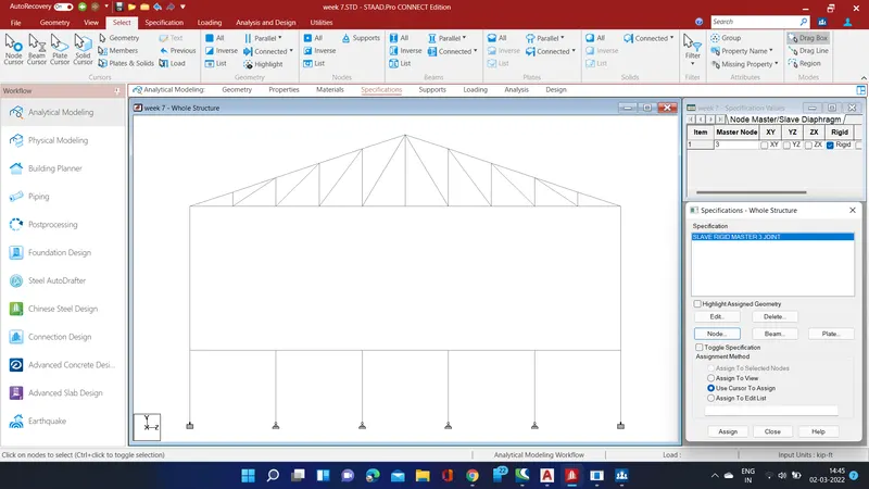
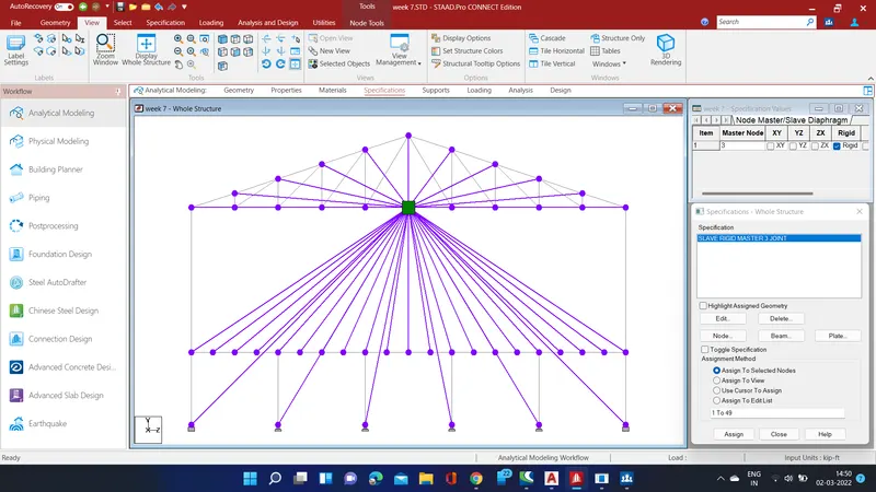
- open the tab specification , where we created a master slave node which is node 3
- it was assigned to all the nodes of the design
- then goto view tab...> select label settings....> click on master slave option and click ok
- we find that all the nodes of the master slave is spoted at the node 3
STEP 6:
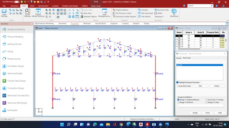
- Go to properties option to work with beta angles
- where the angle which is used is 20 degree and done with the design
RESULT:
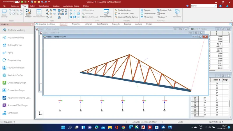
hence the modelling of truss is done as per the data given