Drafting of various geometries using Chamfer, Fillet tool in AutoCad
AIM:
DRAFTING OF VARIOUS GEOMETRIES USING CHAMFER, FILLET TOOLS IN AUTOCAD
INTRODUCTION:
AutoCAD offers various tools to perform different tasks. The various tools which are used for drafting in this project are briefly described here. These tools include: Chamfer, fillet, offset, rotate, object snapping, trim, and extend, lengthen, mirror, and join.
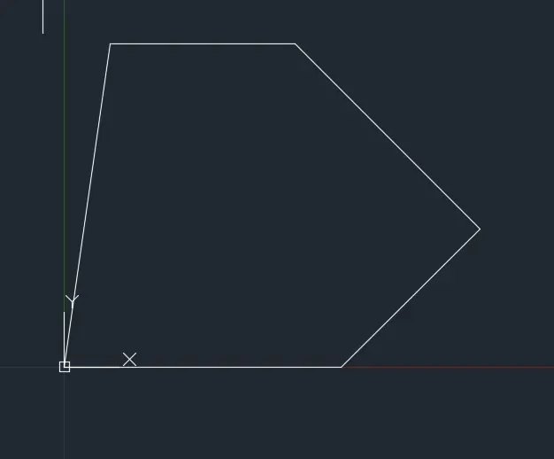
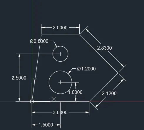
1) To draft the following geometry using decimal system units.
Procedure for drawing the figure is as follows
- Type UN and press enter , under drawing units select the desired unit that is in decimal and apply limits as per requirement.
- Type L in the command line and press ENTER
- Specify the starting point as 1,1
- Specify the next point as @3,0
- Specify the next point @2.12<45
- Specify the next point @2.83<135
- Specify the next point @-2,0
- Specify the next point @0,-2.5
Type L in the command line and press ENTER
- Specify next point a
- Next point @1.5,0
- Next point @0,1
- Specify next point @0,1.5
Type C and press enter specify center point of circle
- Specify center point of circle: c
- Type C and press enter specify center point of :d
- Specify radius of circle 40
After drawing circle delete the lines ab, bc, and cd
Give the dimensions as per the drawing using dimensions command from command bar.
RESULT:
The geometry using decimal units is completed.
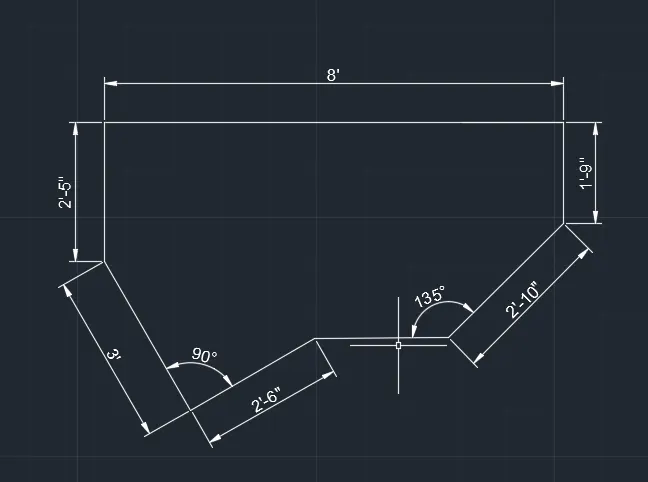
2) TO DRAFT THE FOLLOWING GEOMETRY USING THE ARCHITECTURAL UNIT OF MEASUREMENT
Procedure for drawing the figure is as follows:
Type UN and press enter, under drawing units, select the desired unit that is architectural
- Type L in the command line and press enter
- Specify the start point 2,5
- Specify next point @2’-10<45
- Specify next point @0,1’-9”
- Specify next point @-8’,0
- Specify next point @0,-2’5”
Switch on polar tracking of 30,60,90
Place the cursor at 300 degree tracking and type 3’
Now place the cursor at 30 degree and type 3’
Now place the cursor at 30 degree and type 2’-6”
Give the dimensions as per the drawing using dimensions command bar.
RESULT:
The geometry using architectural units is completed.
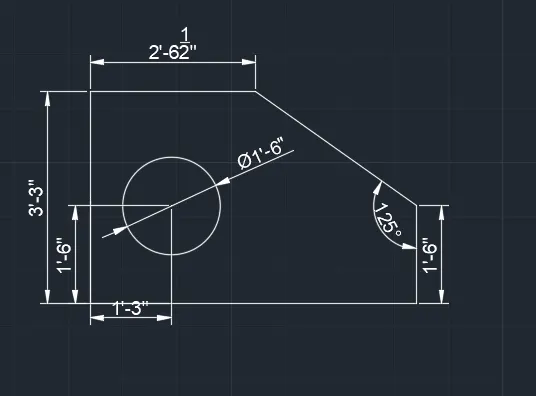
3) TO DRAFT THE FOLLOWING GEOMETRY USING THE ENGINEERING UNIT OF MEASUREMENT
Type UN and press enter, under drawing units, select the desired unit that is engineering.
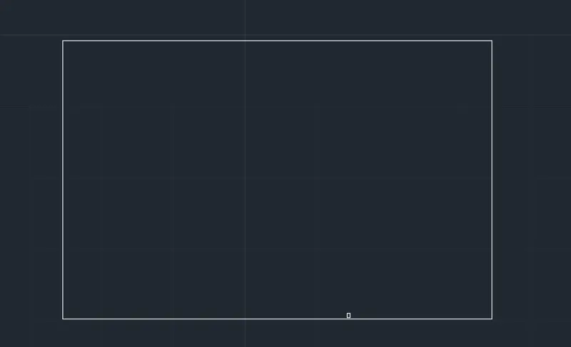
Type REC in the command line and press enter
- Specify the corner point of the rectangle
- Enter D for dimensions
- Enter the length 5’-01”
- Enter the width 3’-3”
- Specify the corner point
Type CHA or chamfer in the command line and press enter
- Enter D for the distance
- Specify first chamfer distance 2’-3.5”
- Select second chamfer distance 1’-9”
Select the first line ab and second line as bc
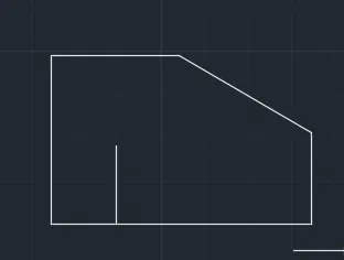
Type L in the command line and press enter
- Specify the start point d
- Specify next point @1’-3.0”
- Specify next point @1’-6.0”
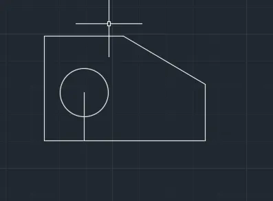
Type c and press enter
- Specify centre point of circle : e
- Specify the diameter of the circle:1’-6.0”
- Delete unwanted lines by trim command
Give dimensions as per dimension command enter DIM in command dialogue box
RESULT:
The geometry using engineering units is completed.
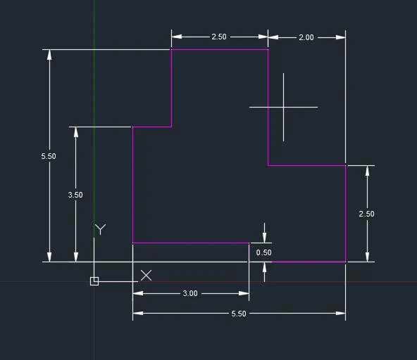
4) TO DRAFT THE FOLLOWING GEOMETRY
Type UN and press enter, under units, select the desired unit that is decimal
Type L in the command line and press enter
Specify the start point 1,1
Specify next point @3,0
Specify next point @0,-.5
Specify the next point @-2,0
Specify the next point @0,3
Specify next point @-2.5,0
Specify next point @0,-2.5
Type L in the command line and press enter
Specify the start point at 1,1
Specify next point @0,3
Specify the next point @1,0
RESULT:
Give the dimensions as per the drawing using dimensions command from the command bar.
The geometry using decimal unit is completed.
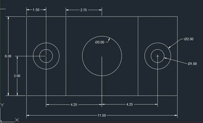
5) TO DRAFT THE FOLLOWING GEOMETRY
Type UN and press enter under the drawing units, select the desired unit that is decimal
Type REC in the command line and press enter
Specify the corner of the rectangle
Enter D for dimensions
Enter the length 3
Enter the width 6
Type L in the command line and press enter
Specify the start point at the first corner point of the rectangle
Specify the next point @1.5,0
Specify the next point @0,6
Turn on midpoint in object snap
Type c and press enter
Specify the center point of the circle
Specify the radius of circle as .5
Type O or offset on the command line and press enter
Specify the value of offset distance .5
Select the circle to offset and click outside the circle
Type REC in the command line and press enter
Specify the first corner of the rectangle
Enter D for dimensions
Enter the length 5.5
Enter width 6
Specify the other corner
Trim and erase the unwanted lines
Type CO and press enter
Select the rectangle and click D for displacement and type @8.5,0 specify the base point as a and click enter
Trim and erase the unwanted lines
RESULT:
Give dimensions as per the drawings using dimensions command from the command bar
The geometry using decimal units is completed.
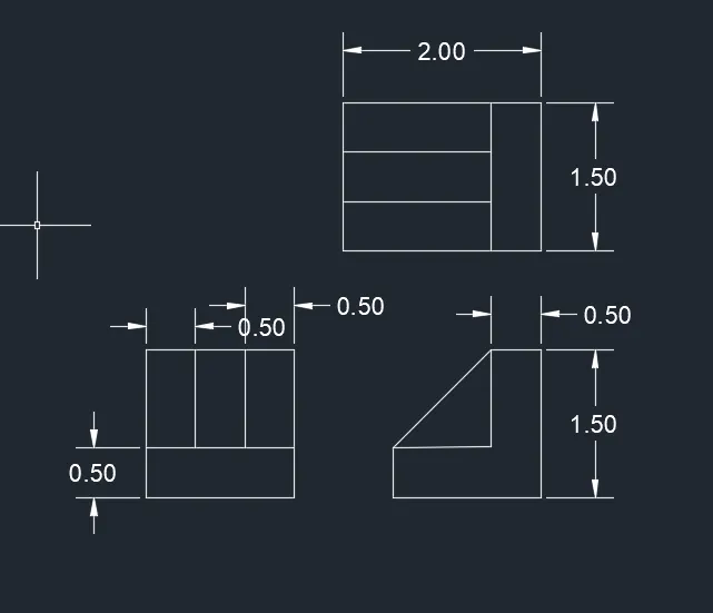
6) TO DRAFT THE FOLLOWING GEOMETRY
Type UN and press enter under the drawing units, select the desired unit that is decimal
Type L and press enter
Draw a line 2 units to right side and 1.5 vertically upward and 2 units left side .
Then make offset right side corner of bottom line 0.5 and same vertically upward 0.5 from bottom line 2 and trim unwanted lines.
Using the command L first point towards right 2.0 and upwards 1.5 and left side 0.5 then downwards 1.0 then close
By using ortho mode on by using rectangle command draw a square of 1.5 x 1.5 units
Offset distance 0.5 from the left to right side of the rectangle and trim the unwanted lines
RESULT:
Give dimensions as per the drawings using dimensions command from the command bar
The geometry using decimal units is completed.
7) TO DRAFT THE FOLLOWING GEOMETRY
Type UN and press enter under the drawing units, select the desired unit that is decimal
Type L and press enter
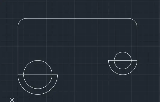
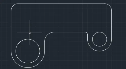
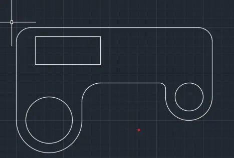
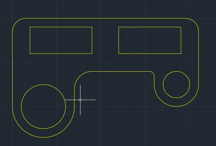
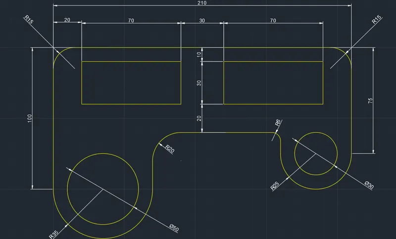
Draw the line 100 units vertically upwards and right 210 units and vertically downwards 75 and click enter
By using offset distance 10units 40, 60 from the top line to downwards
Again using offset command entering distance 20 units 90, 120, 190 from the left side to the right side
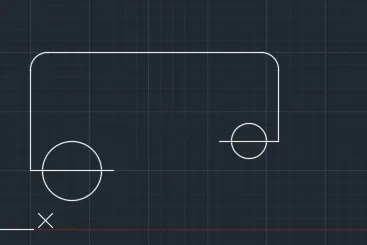
In command line center C take two points method bottom corner 100 first and second 70 distance
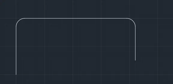
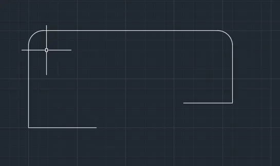
Draw a circle diameter 50 and lime first point 35 radii of circle above the offset line and use fillet radii 20. Remove unwanted lines by using trim command
In the command line enter C take two point method bottom corner 75 first and second point 50 distance. Draw a circle dia 25 line above offset and fillet radius 6
Using fillet command select object top left corner line and radius 15 and same process at the top right corner
RESULT:
Give dimensions as per the drawings using dimensions command from the command bar
The geometry using decimal units is completed
8) TO DRAFT THE FOLLOWING GEOMETRY
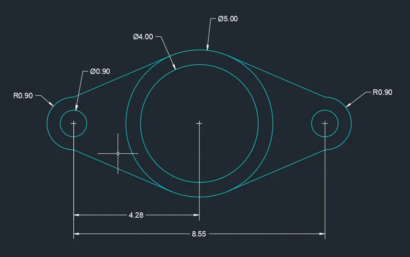
Draw a dia 4 and specify the center line dia 4 and another circle 5 wit the same center
Draw a line 4.275 from the center of the circle using line command and using command C specify the center at the end of line and click on dia and give 0.9 units
Same center line another circle dia 0.4
By using polyline draw a tangent to the top of the circle of radius 0.9 first circle dia 5 in top and bottom on the both sides and trim the unwanted lines
By using mirror select the two circles and tangents specify base points as a center 5 units dia and place it at the other side of the line and press escape
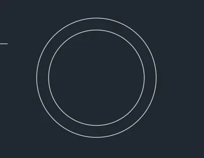
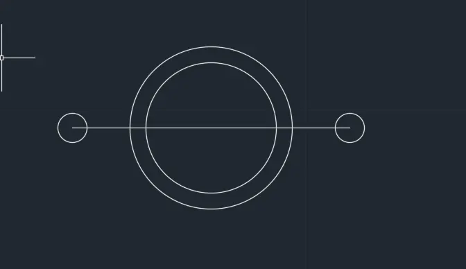
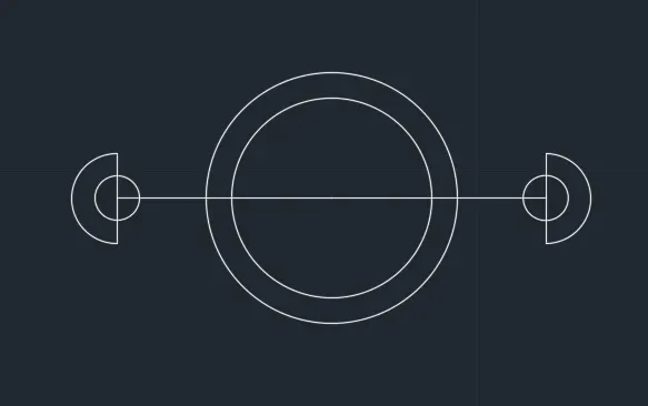
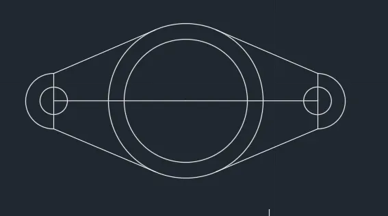
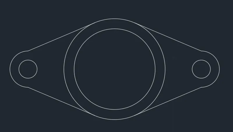
RESULT:
Give dimensions as per the drawings using dimensions command from the command bar
The geometry using decimal units is completed
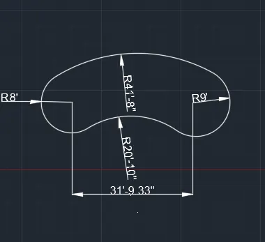
9) TO DRAFT THE FOLLOWING GEOMETRY
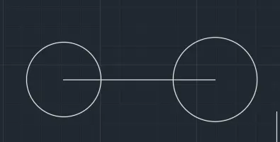
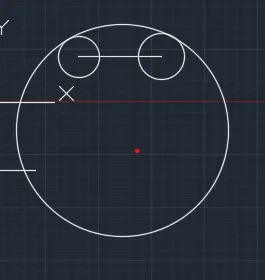
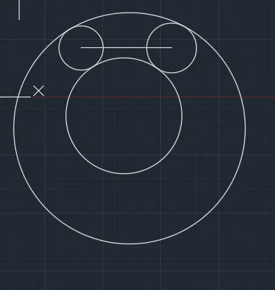
- draw a line 32'6" take the center as endsof the line draw two circles as ends of the line draw two circles of radius 8' and 9'
- to draw the bottom arc, draw offset to both the circles with offset distance as radius of the bottom arc
- command CO circle offset distance as 20'10" intersection of the two circles from the intersecting points
- draw a circle with center as intersection point of the offset circles and radius 20’10”.
- Trim the rest of the figure to get an arc and thus an arc of 20’10” will be formed draw the upper curve
- Draw a circle with radius 32’8” wit center same as that of radius 9’ circle
- Draw another circle with center as the intersecting point of the bottom circles and with radius 41’8”
- It passes through the two circles of radius 8’ and 9’
- Trim off the rest so that an arc of radius 41’8” is formed between the tangents. Trim the part of the circle and the line connecting the center of circles
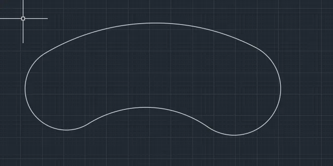
RESULT:
Give dimensions as per the drawings using dimensions command from the command bar
The geometry using decimal units is completed
10) TO DRAFT THE FOLLOWING GEOMETRY
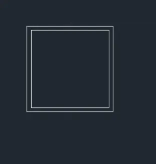
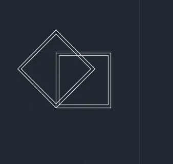
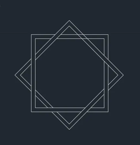
Draw a rectangle at a point in the plane and dimensions length 5 breadth 5 and offset 0.2 inside rectangle
Copy the square and rotate the square and select base point from bottom by 45 degree and trim unwanted lines.
RESULT:
Give dimensions as per the drawings using dimensions command from the command bar
The geometry using decimal units is completed
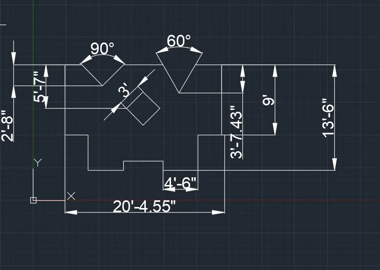
11) TO DRAFT THE FOLLOWING GEOMETRY
Units are in feets and inches by using line first point plane and move cursor right side 10’2” and move the cursor downwards and enter 9” and move the cursor left side and enter 3’ and move the cursor downwards and enter 4’6” and move the cursor left and enter 4’6”
Move the cursor upward enter 1’12” in the command line enter MI select all the objects and click on enter select base point and mirroring the image
Give offset line of distance 3’7” horizontally by offset command O give offset line at the midpoint of top 10’2” line and vertically by offset command O on the both sides such that the include angle is 60-degree and 30 degree on both side of vertical line
Similarly on the other side take an offset of midpoint of top 10’2” line and from the corner 2’8” from the top and draw the inclined lines such that the included angle is 90 degree
Take offset distance of 10’2” from the corneer and 6’10” from the top with offset command intersection point as center draw a diamond with radius 3 and anglre 90 degree
RESULT:
Give dimensions as per the drawings using dimensions command from the command bar
The geometry using decimal units is completed