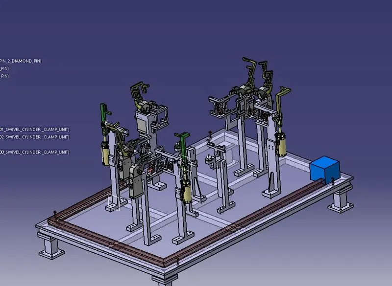
Week 7- Base Unit Design Challenges 2
Aim
Design a base units for the units designed such as pin and clamp units in theprevious challenge with all weldments for the given car panel. Design thecomplete fixture assembly and constrained the panel using 3-2-1 principle.
Base Unit
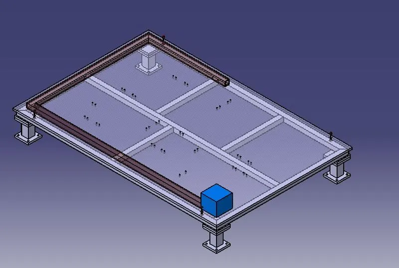
All other assembled units, such as clamps, pins, and swivels, are secured to a base unitpresented in the below figure. Other components required for operation include the valve box, Trunking channel, base plate, measuring hole cover, eye bolt, pedestal, weld bars, and floor plate, which are all included with the base unit. A trunking cable path is also supported by the base unit. The base plate is made of steel and aluminium and ranges in thickness from 25 to 40mm. A number of holes in the base plate have been drilled to serve as mounting points for theclamp unit, pin unit, and so on. A base plate size must be designed with the BCS co-ordinate
system in mind, as it covers all units with its outer peripheral individual opening.
The procedure for creating the base unit is as follows:-
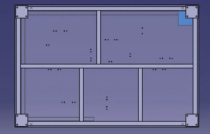
1.A Rectangular Base plate is created with required dimensions, and make sure that every
unit must be inside by around 25 mm from the outer edge.
2. Further base plate is supported by square tube with good strength (50x50x3mm) from all
four side. Also one middle support is provided for betters support.
3.Below the base plate small square plates are created for mounting of base plate and legs.
4. Further four Pedestal (resting legs) were created with square tubes.
5.Finally, the lower plate for the leg to stay were created which will support the base leg
The 3-2-1 principle is used.
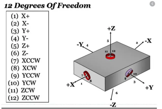
The workpiece has twelve Degree of Freedom. six transitional DOF and 6 rotational DOF.
Transistional: X, -X, Y, -Y, Z, -Z.
Rotational:Â Clockwise around X axis (CROT-X); Anticlockwise around X axis (ACROT-X); Clockwise around
Y axis (CROT-Y); Anticlockwise around Y axis (ACROT-Y); Clockwise around Z axis (CROT-Z);Â Â Anticlockwise around Z axis (ACROT-Z).
The rotational DOF have to be constraint.
Using 3-2-1 priciple.
First the workpiece is constraint by 3 pins on below surface. This lock the Y DOF,Clockwise around X axis
(CROT-X); Anticlockwise around X axis (ACROT-X)  the Clockwise around Z axis (CROT-Z);  Anticlockwise around Z axis (ACROT-Z).
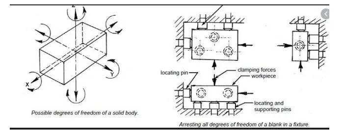
Then another side perpendicular to the below surface is constraint by 2 pins. This locks -ZÂ and +ZDOF and
Clockwise around Y axis (CROT-Y); Anticlockwise around Y axis (ACROT-Y).
Then any one side perpendicular to both the below and the other 2 side of the workpiece is constaraint by 1 pin. This
locks X DOF.
Then another side perpendicular to the below surface is constraint by 2 pins. This locks -ZÂ and +ZDOF and
Clockwise around Y axis (CROT-Y); Anticlockwise around Y axis (ACROT-Y).
Then any one side perpendicular to both the below and the other 2 side of the workpiece is constaraint by 1 pin. This
locks X DOF.
The 3 points are used as 3 points to define a plane. Four points cannot be used due to irregularity of the surface in
real world.
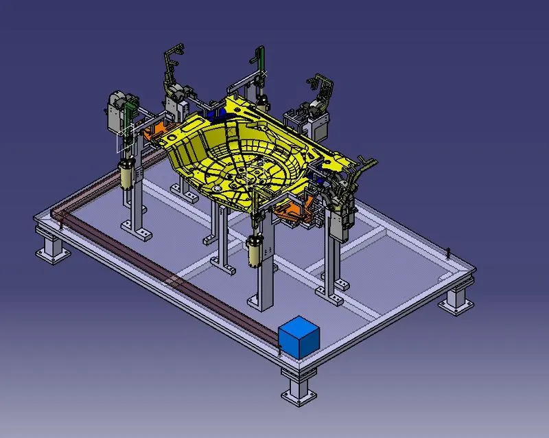
Design a base units for the units designed such as pin and clamp units
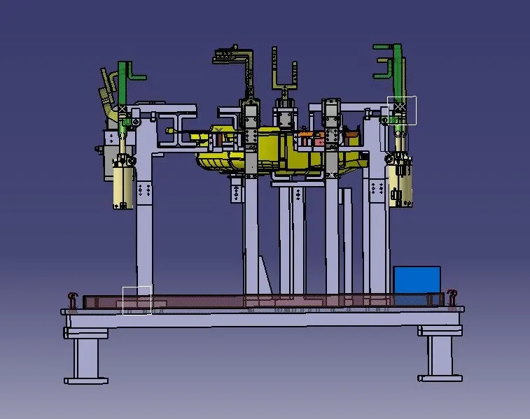
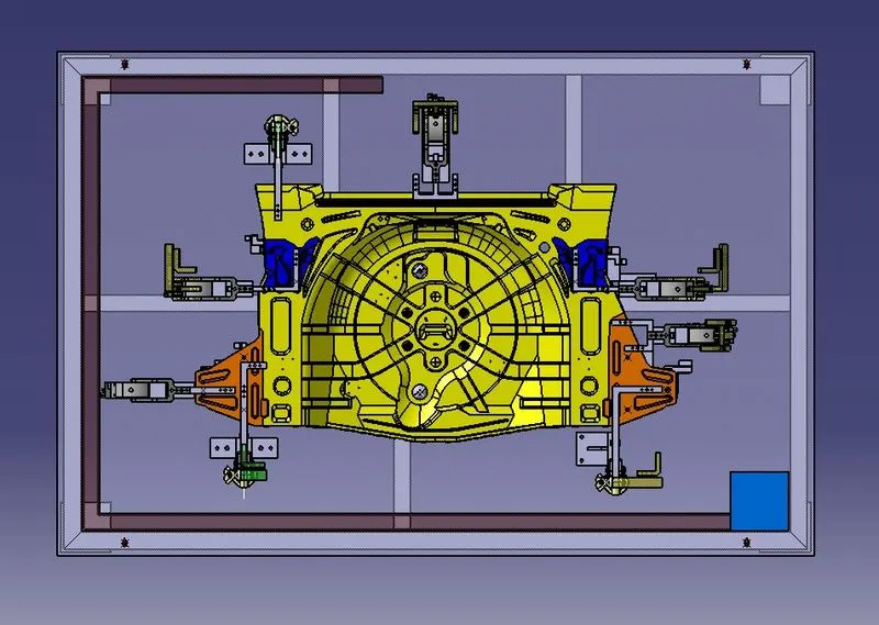
Hole on base plate
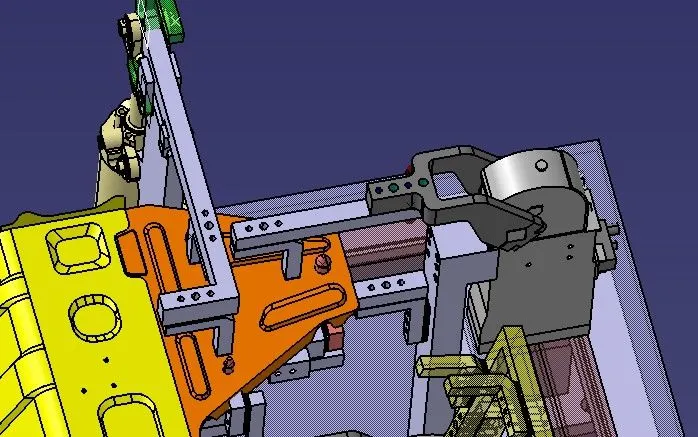
For Orange pin,clamp units and hole
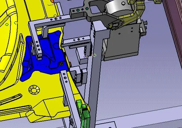
For Blue pin,clamp units and hole
For Orange , blue and yellow pin,clamp units and hole
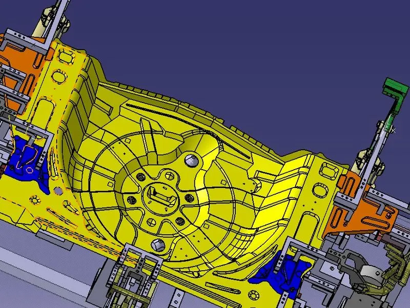
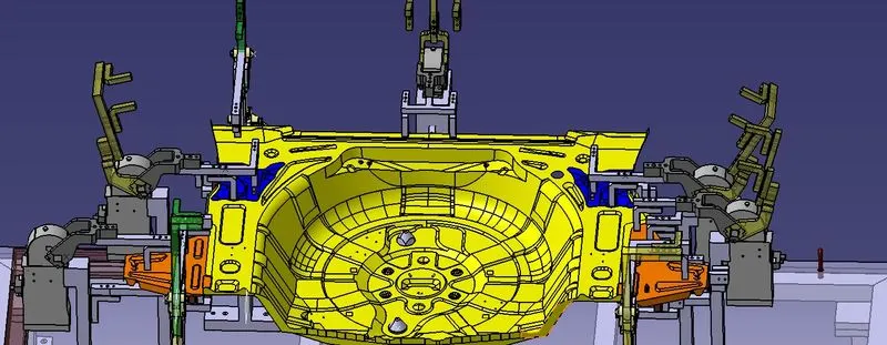
Different units used to restrict the movement, so any operation can be done properly.
Total swivel clamp with pin: 03
Total clamp units:05
Total pin units: 02
Total rest units: 02
base unit -01