Week 7- Base Unit Design Challenges 2
Objective
1. Design a Base unit for the the unit designed for the above challanges with all weldments for the given car panel
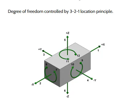
2. Design the complete Fixture assembly Make all the 5panels given in the cad data fully consttrained with the 3-2-1 principle
Base Unit
Base unit is the unit of the fixture which is designed as such so that other unit of the fixture can be mounted on it . Apart from these unit other necessary tools like penumatic valve box trucking cable path will also be mounted on the base unit
Base unit is the fundamental componet of the fixture because all other component are mounted over it so every fixture have base unit
the base unit design is different according to the panel . Design of clamp system , locating system ect
Part of Base unit
1.Base plate pedstal
2.Trunking channel
3.valve Box
4.Eye Bolt
5.Floor Plate
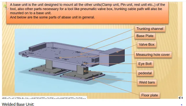
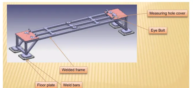
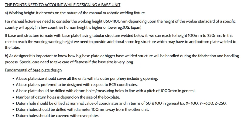
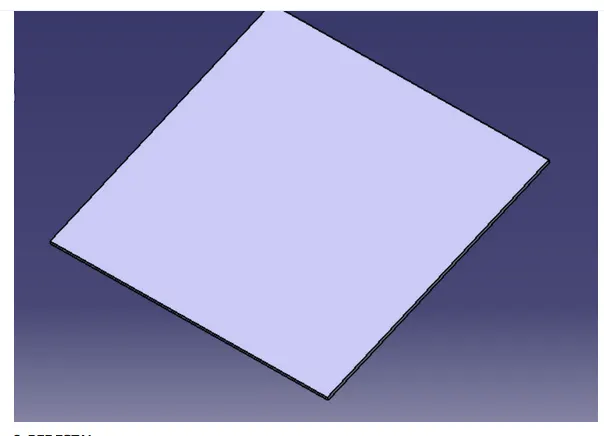
Base Plate is a machined plate 25 to 40mm thickness made of steel and aluminum on which the hole are drilled to mount individual unit like clamp unit pin unit rest unit ect
2. Pedestal
A pedestal is a part which connect the base plate to the floor plate. A pedestal is a standard part in genaral and in some cases it can be welded frame intergated with the base plate
FUNDAMENTAL OF PEDESTAL DESIGN
A Standard pedestal can be different height and different size
Depend on the size of the base plate the number of pedestal varies for load distribution
A pedestal are of different types with different inclination
TRUNKING CHANNEL
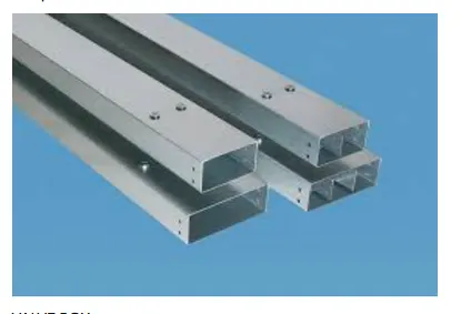
A Trunking channel is a duct which accomdated all the pneumatic and electrical hoses and wires for the unit of the tool . the trunking channel includes all the pressure inlet cables going to the penumatic parts of the fixture and protect them from damaging while operation is in process
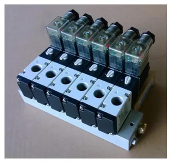
VALVE BOX
Valve Box is standard part which will accomodates the penumatic valves for the units. it is kind of control units. the valve box is the box which includes different solenoid valves which is used to control the valves
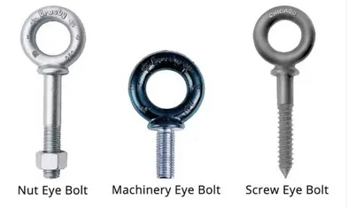
Eye Bolt
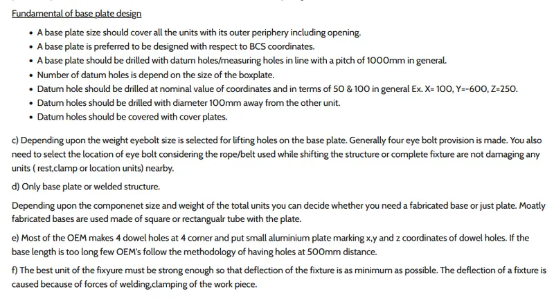
Eye bolt are used for the transporting of the using lift hooks, forks lift holes will also be provided in some cases for transporting purposes . we usually use M20 bolts that are base plate
Floor Plate
Floor Plate is grouted to the floor with fixed bolt on the ground. Floor plates are called as Foundation plate
Fundamental of Floor plate Design
There is a Clearance of 10mm maintained between the pedestal base plate and the floor plate
This clearance will be used by the leveling screw for leveling the entire tool.
Weld bars are weld the position permentaly after leveling is done
A weld bar is a plate along the side of the base plate of the pedestal