Week 7- Base Unit Design Challenges 2
AIM:
To Design a base unit for the Pin units, Clamp units, Swivel clamp units with all weldments for the given Car panel.
SOFTWARE USED:
CATIA-V5 INTRODUCTION:
Base Unit:
- A base unit is designed to mount all other units(Clamp unit, pin unit, rest unit, etc) of the tool, also other parts necessary for a tool like Pneumatic valve box, trunking cable path will also be mounted onto a base unit. And below are some parts of a base unit in general.
- They are trunking channel, base plate valve box, measuring hole cover, eye bolt, pedestal, weld bars, and floor plate.
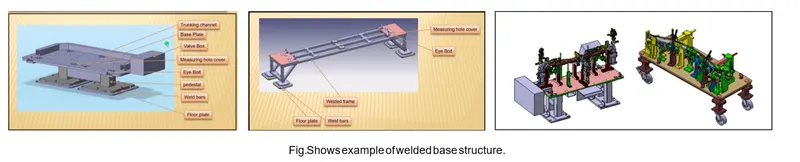
TYPICAL PARTS OF BASE UNIT:
BASE PLATE:
- The base plate is a plate of 25mm to 40mm thickness.
- The base plate has no holes on it which will act as mounting points for the clamp unit, pin unit, etc. of a tool.
PEDESTAL:
- It is used to connect the base plate with a floor plate.
- The pedestal can be a standard part of a make part, depending on the size and height of the fixture.
- Standard pedestals are available in different heights.
- Pedestals are also available in different inclinations.
- Depending on the size of the base plate, the number of a pedestal for a fixture can vary for load distribution.
TRUNKING CHANNEL:
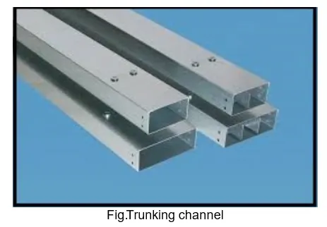
- A Trunking channel is a duct that carries all the electrical and pneumatic connections (wires and pipes) for units of the tool. It has a thickness of few millimeters.
VALVE BOX:
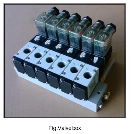
- The valve box is a standard part that will accommodate all the pneumatic valves for the unit.
- The valve box is the box that includes different solenoids valves.
- The trunking channel includes all the pressure inlet cables going to pneumatic parts of the fixture & protects them from damage while the operation is in process.
EYEBOLT:
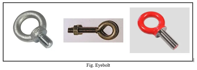
- Eyebolts are the bolts that are used to lift fixtures for transportation by inserting hooks into them. For example, usually, we use M20 bolts that are bolted on the base plate.
- Used for transportation purposes, sometimes forklift holes will be provided.
FLOOR PLATE:
- The floorplate is grounded to the floor with a fixed bolt on the ground.
- Floor plates are also called foundation plates.
- There will be a clearance of mm maintained between the pedestal base plate and the floor plate.
- This clearance will be used by the leveling screw, for leveling the entire tool.
- Weld bars are used to weld the positions permanently after leveling is done. A weld bar is a plate along the sides of the base plate of the pedestal.
Fundamentals Of a Base Plate Design:
- A base plate size should cover all the units with its outer periphery including the opening.
- A base plate is always preferred to be designed with respect to BCS coordination.
- A base plate should be drilled with datum holes / measuring holes in line with a pitch of 1000m in general.
- The number of datum holes depends on the size of the base plate.
- Datum holes should be drilled at nominal valves of coordinates and in terms of 50 and 100. Example X=100, Y= -600, Z=250.
- Datum holes should be covered with cover plates.
Points to be considered while designing a base plate:
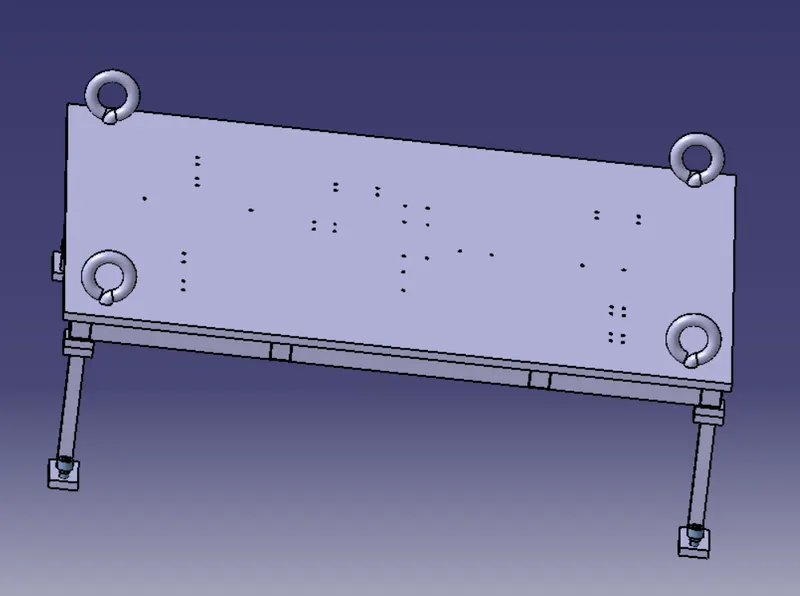
Working height: It depends on the nature of the manual or robotic welding fixture. For manual fixtures we need to consider the working height 850-1100 mm, depending upon the working height of the worker standard of a specific country will apply (in few countries human height is higher or lower e.g. (US, Japan). If the base structure is made with a base plate having a tubular structure welded below it we can reach the height of 400 mm to 550 mm. In this case to reach the working welding height we need to provide additional leg structure which may have top & plate welded to the tube. The total working height of this unit is 1200 mm. The Dimensions of the Base Plate are obtained as 1500x1600x20mm.
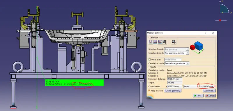
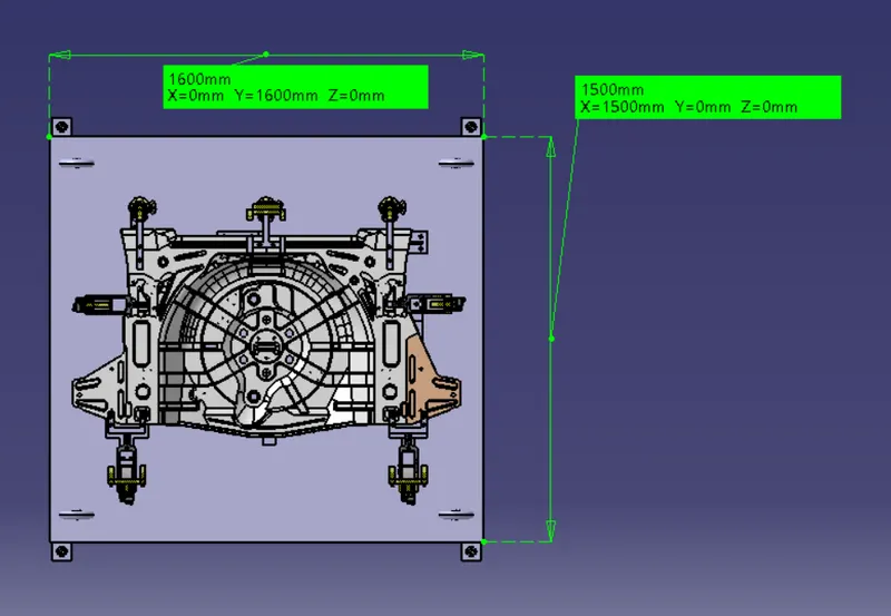
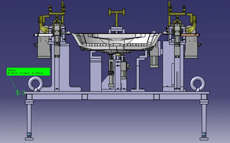
- The base unit of the fixture must be strong enough so that deflection of the fixture is as minimum as This deflection of the fixture is caused because of forces of welding clamping of the workpiece. The base plate is 20mm in thickness, which is machined to maintain the parallelism which can easily sustain a load of units without deflection. The weldment support and leg assembly part are made up by using a 35x35x290mmx5mm thick seamless pipe which can withstand the forces caused by welding and clamping of the workpiece.
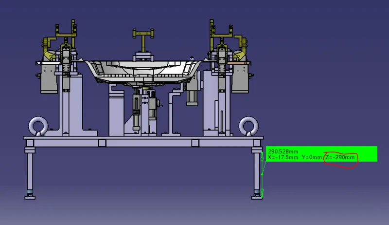
- The Base unit of the fixture should have the mass to prevent vibration and The designed base unit weight 65 kg which is good enough to prevent vibration and chatter.
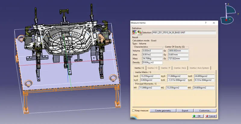
- The base unit may be built from simple sections so that other units may be fastened with screws or welded whenever necessary. Those parts of the fixture that remain permanently with the fixture may be Those parts that require frequent changing may be held with screws. The permanent parts of the base units are welded together and other parts have the facility to be fastened to the base unit. all the rough locators & the units can be fastened by using threaded bolts. The base plate is designed to assemble these units without being failed to each other.
- The base units should cover all the units within its outer periphery including
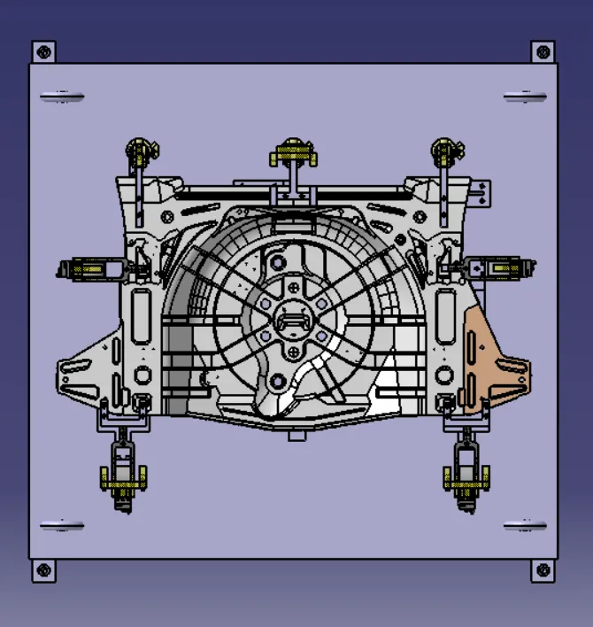
- The base unit should be parallel to the floor, to adjust this there should be the provision of height adjusting The height adjusting mechanism is provided to maintain the parallelity of the floor. at the time of adjustment, we can provide spacers in order to maintain the parallelism with the floor.
3-2-1 Principle:
A workpiece free in space can move in an infinite number of directions. For analysis, this motion can be broken down into 12 directional movements or "degrees of freedom". All 12 degrees of freedom must be restricted to ensure proper referencing of a workpiece.
The 12 degrees of freedom all relate to the central axis of the workpiece. Notice the 6 axial degrees and 6 radial degrees of freedom. The axial degrees of freedom permit straight-line movement in both directions along the 3 principle axis shown as X, Y & Z.
The radial degrees of freedom permit rotational movement, in both clockwise & counterclockwise radial directions around the same three-axis.
A rigid body in the plane has 6 degrees of freedom (i.e) The motion of a ship at sea has 6 degrees of freedom.
X+
X-
Y+
Y-
ZCW
ZCCW
Now try to understand the 3-2-1 principle of the fixture. The purpose of the Fixture is
Resting
Locating
Orienting
Clamping
Resting:
- In a fixture, the workpiece should rest in such a way that it doesn’t move or vibrate on the resting blocks.
Locating:
- The fixture should locate the workpiece such that all the operations to be performed on it are performed without any problem and all of them are performed effectively.
Orienting:
- The fixture should orient the workpiece such that all the operations to be performed on it are within the reach of the workpiece.
Clamping:
- A clamp is a fastening device used to hold or secure objects tightly together to prevent movement or separation through the application of inward pressure. There are many types of clamps available for many different purposes. Some are temporary, as used to position components while fixing them together, others are intended to be permanent.
Achievement of 3-2-1 Principle:
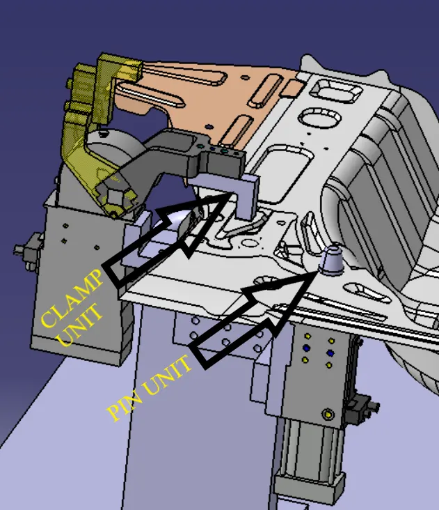
- This requires a minimum of three locator blocks to establish the part plane. Three locators or supports are placed under the workpiece. Three locators are usually positioned at the primary locating surface.
- The Clamp unit restricts 2 axial movements Upward and downward and the other 2 pin units restrict radial movement. As by the 3-2-1 method, introducing a minimum of 1 clamp and 2 pins will restrict 6 degrees of freedom(DOF).
Clamp Plan:
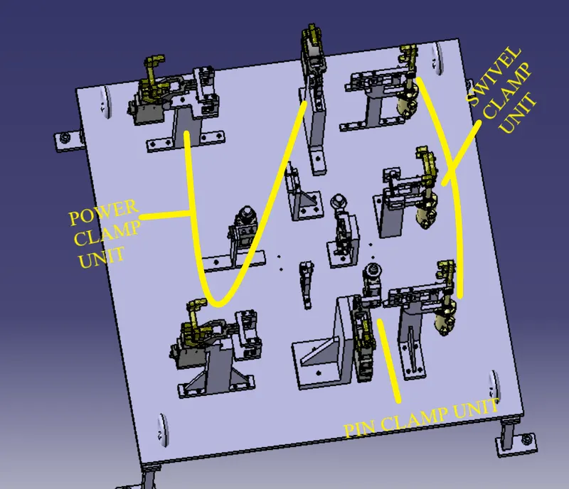
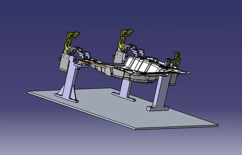
- In This assembly, all 5 panels are fixed by using the 3-2-1 Principle.
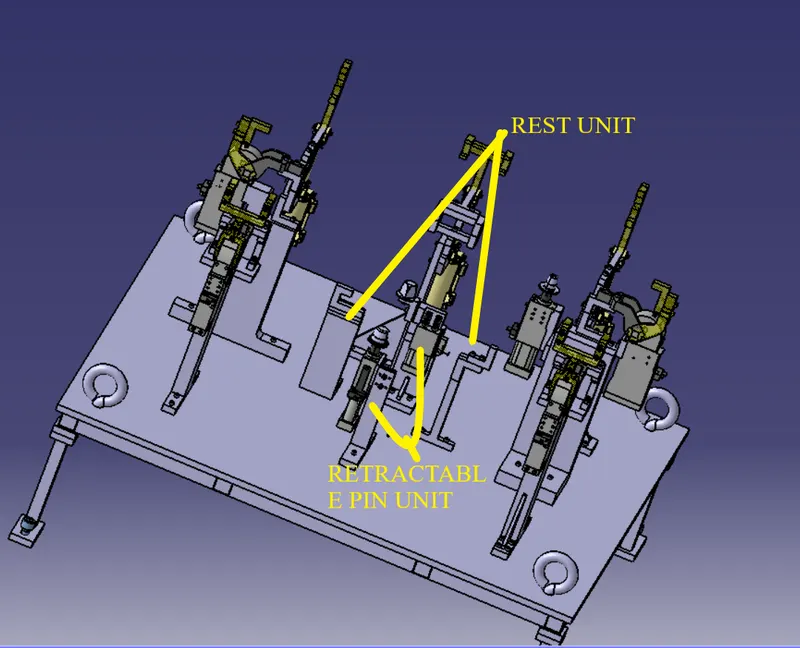
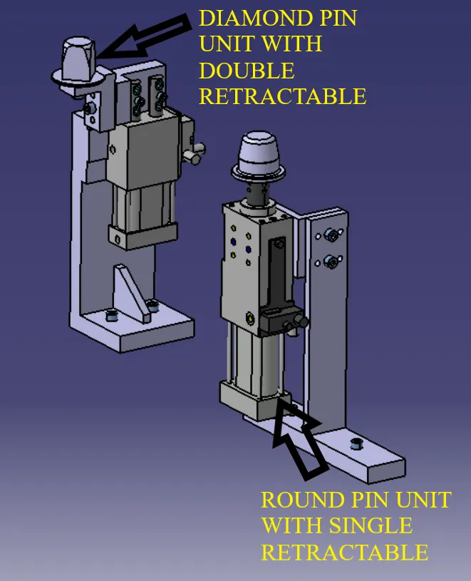
- The Front Side panels are fixed by using a Pin clamp unit with a two-way clamping Clamp mylar and a retractable pin unit with a diamond Pin.
- The back side panels are fixed by using a Pin clamp unit with a two-way clamping Clamp mylar and a retractable pin unit with a diamond Pin.
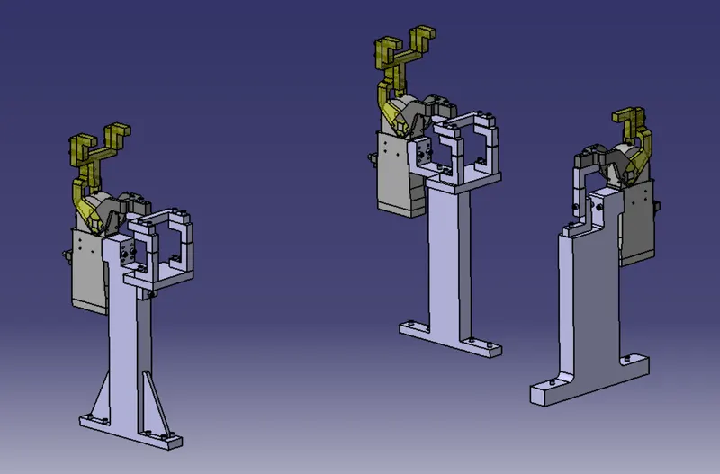
- The Centre Panel is locked by using two rest units at the bottom,two-pin units into the holes to lock rotation movement, and 4 swivel cylinders in the front and three power clamp cylinders at the back.
- In this way, by using all these units the panel is locked by using these units.
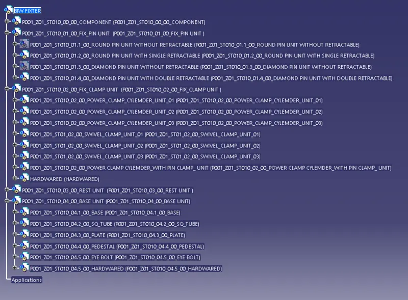
Structure of Design tree:
- A process where all the assemblies and parts are named in specific standards Different customers have different sets of standards and the structure of the design tree.
- Every company, every customer has different standards of their own structural design tree.
- So they will be giving a template on how the structuring and detailing of the design are done. And you have to follow that particular design or structuring of the tree.
- In the design tree itself if we mentioned that particular name, wherever that part is we can easily know that this part belongs to this one or this station or this assembly on a particular unit. So this helps us to avoid errors during the design study, manufacturing assembly, and inspections.
- It is an important process that helps us to identify a specific part or assembly as to which project, tool, it belongs to. Structuring a design tree is actually to avoid the errors, which might come during manufacturing assembly, or either in-house inspections as well.
- If the part or assembly are not named properly, or the design tree is not structured properly, it will create confusion to understand the design and may create major possibilities of making an error.
- Every part, every component should be named according to their procedures.
- If we did a mistake or renamed the entire standard parts from the customer as a design part. Now the customer is going to manufacture the entire part again from the scratch, but he already has that product in his itinerary. but extra cost extra time and is feasible. This is also known as an error which is actually going to increase the cost of the entire assembly as well Naming a fixture or a unit or a part gives the information as to which project zone or assembly do they belong.
- If we name the part properly or name the fixture properly ill actually tell which unit or which assembly or which zone or in which station it actually belongs
- It can help us to identify the number of items of the same types or different types that are being used in an assembly. While starting of designing a fixture, The first unit will be the base unit.
- In a Design tree, all the manufacturing parts should be first and the standard parts should be at the last. Design tree helps to study or understand the parts in the assembly easily.
DESIGNS USED IN THE ASSEMBLY:
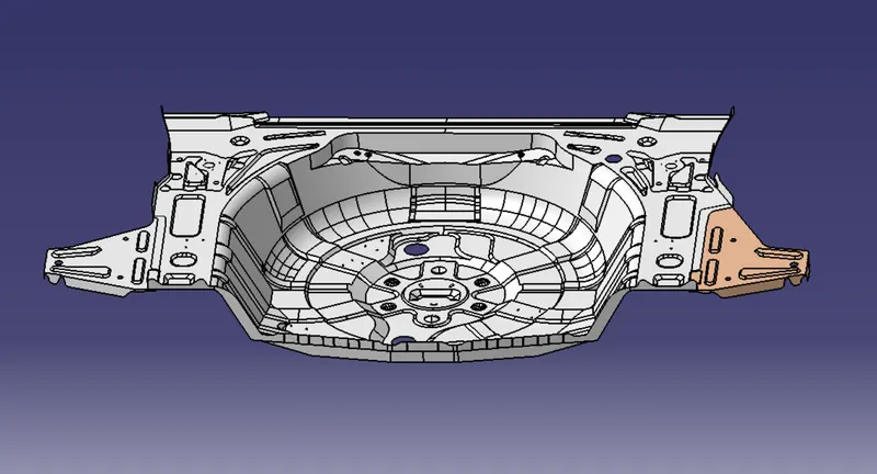
Design of the given Car Panel:
Design of the Base Unit:
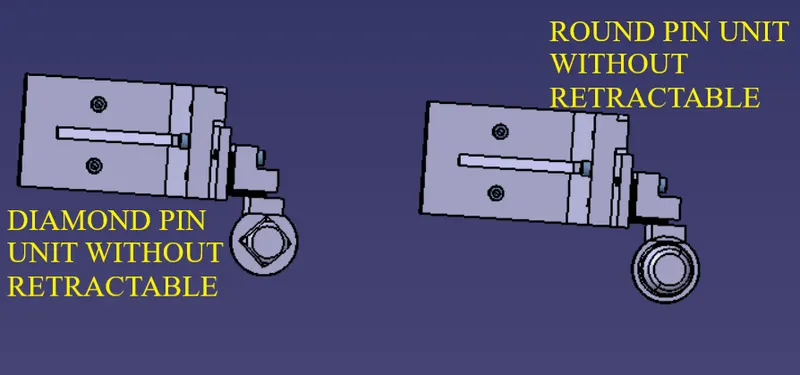
Design of the Pin Units:
WITH RETRACTABLE
WITHOUT RETRACTABLE
Design of the Power Clamp Units:
Design of Swivel Clamp Units:
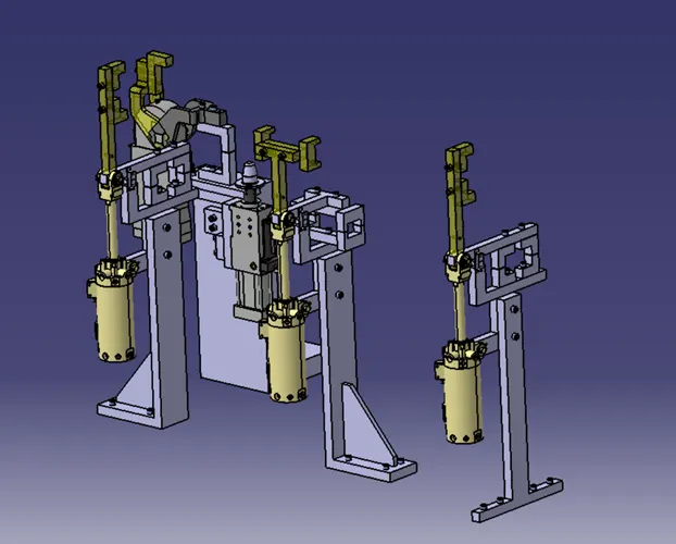
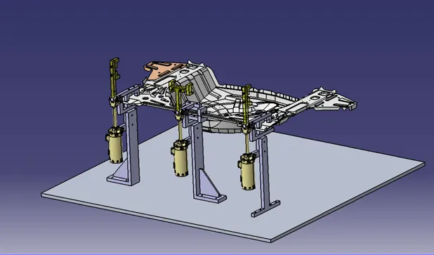
Design of Pin Clamp Units:
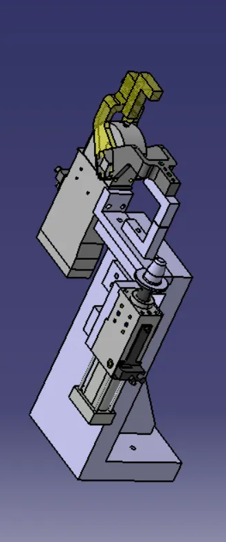
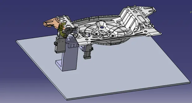
Design of Rest Unit:
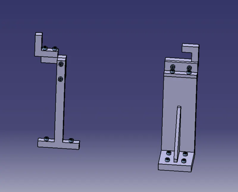
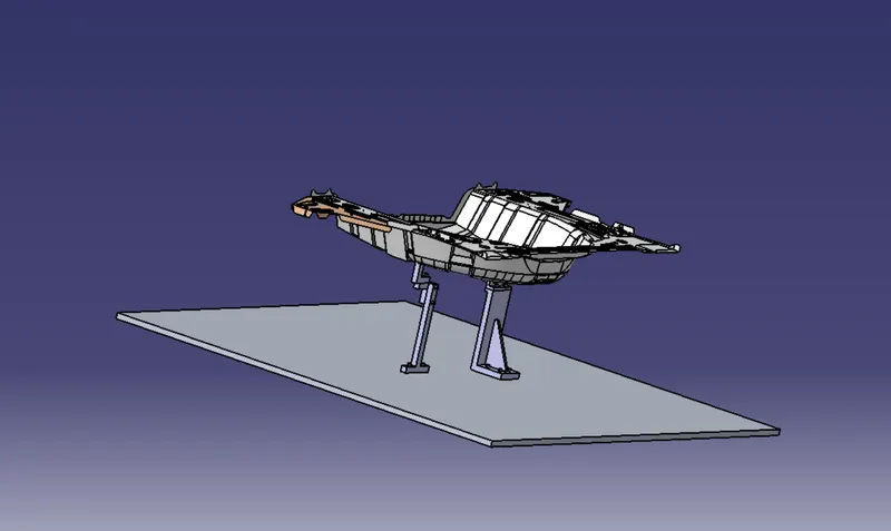
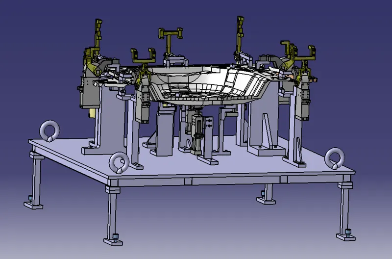
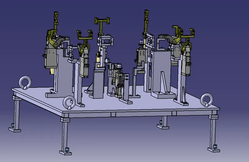
Assembly of the units:
With Car Panel
Without Car Panel
CONCLUSION:
Thus a base unit is designed with all the weldments for a given car panel and all the other remaining units have been designed for the given car panel and fixed its movement using the 3-2-1 Principle.