Week 7:- Base Unit Design Challenges 1
Q1-What is the Base Unit? What are the typical parts of the Base Unit?
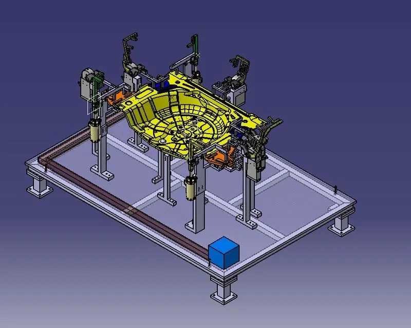
A1-A base unit is the unit designed to mount all the other units of the tool(calmp and pin unit). Other part necessary for a tool like pneumatic valve box . trucking cable path will also be mounted on to a base unit
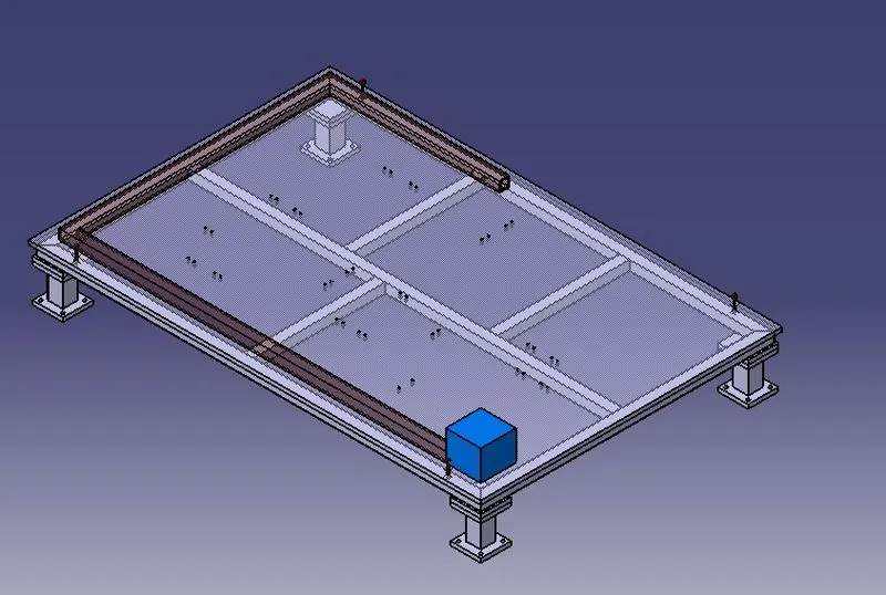
Trunking Chanenel -A traunking channel is a duct which accommadates all tha pnenumatic and electrical hoses and wires for the units of the tool
Base Plate -Machined plate 20 to 40 mm thickness made of steel and alumiuium on to which the holes are drilled to mount the individul unit like clamp unit pin unit of tool
Valve Box- Valve box is a standard part which will acoommodates all the pneumatic valves for the units
Eye Bolt -Eye bolt is use for the transporting of the tool using lift hooks
Weld Bars-Weld bars are be used to weld the postion permunently after leveling
Pedestal-Connects the plate to the floor plate . standard part in general and same cases it can be welded frame integrated with base plate
Floor Plate-floor plate is grouted to the floor with fixed bolt on the ground
Q2-What are the points need to account while designing a Base unit?
A2- following points needed to desging the base unit
Working Height - This is determined by the type of manual or robotic welding fixture. For manual fixtures, we must consider the working height of 850-1100mm, depending on the worker's working height, and the standard of a specific country will apply (in few countries
human height is higher or lower e.g. US, Japan)
The clearance between the pedestal base plate and the floor plate should be kept at 10mm. This clearance will be used for levelling by the levelling screws. The base unit should include some openings for free movement of workers as well as cover all of the units within it.
The size of an eyebolt for lighting holes on a base plate is determined by the weight. For lifting holes on the base plate, four eye bolts are usually chosen. You must also choose the location of the eye bolt so that the ropes/belts used to shift the structure or entire fixture do not damage any
units (rest, clamp, or locating units nearby).
The fixture's base unit must be strong enough to allow for as little deflection as possible. The deflection of a fixture is caused by welding forces and clamping of the workpiece.
The base unit should not vibrate, so it should have enough mass to prevent vibration and other distribution, as well as consider the flatness of the base plate.
The base unit's outer periphery, including the opening, should cover all of the units. From the top, there is enough space at all boundaries.
1. A base plate size should cover all the unit with its outer periphery including opening.
2.A base plate is prefered to be design with respect to bcs coordinate.
3. A base plate should be drilled with dtaum holes measuringholes in line with pitch of 100cm in general
4.Datum holes should be drilled at nominal vales of coordinete
5.datum holes should be covered with cover plate
Q3-What is a Dump unit?
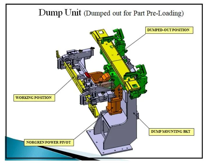
A3-Dump unit is the complex unit to design due to space constains there is less space avilable & have to adjust all the parts in available space. It consist of dump cylinder to perform the operation of clamping & unclamping car pane.
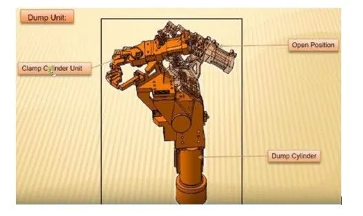
Q4-What are the points you need to consider while designing a Dump unit?
A4-Dump units are used when we cannot use normal units like clamp units, pin units etc. Due to some space constants. For designing this unit one should consider the fallowing cases:-
The 3-2-1 principle of location (six point location principle) is used to constrain the movement of workpiece along the three axes XX, YY, and ZZ. This is achieved by providing six locating points, 3 pins in base plate, 2 pins in vertical plane and 1 pin in a plane which is perpendicular to first two planes
It contains the dump unit's cylinder, which will be the heavier part in all units; the riser and blade should be strong enough to support the cylinder and all units.
In this case, we can use any cylinder that meets our needs. Both clamp and hinge cylinders can be used.
The total weight of the assembly should be as light as possible. As a result, less force is required to push and pull it in order for it to perform the required operation.
The opening and closing time of clamp should be less as much possible for the smooth operation.
The parts should be designed with the open state of the unit in mind. The parts should not fall to another unit while the unit is open.
The Design parts should be small in size but can do their functions effectively
Q5-What is a Slide unit?
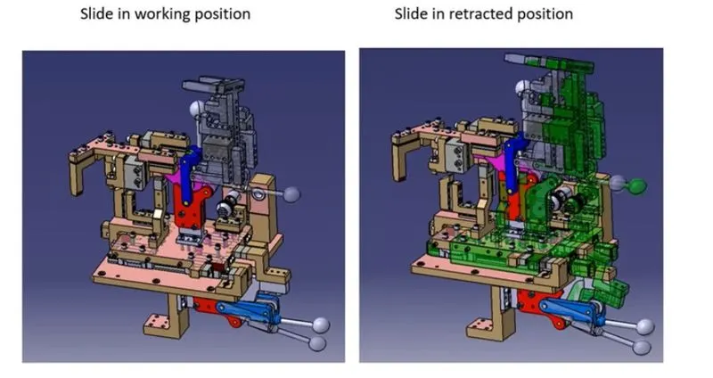
A5-It is used when space is restricted and we do not have enough space to design and assemble various customised units. The slide unit is employed in these situations. In order to complete the operation, slide units are used to place the fixtures, weld gun, units, and robots. Varied slider units, such as CNC, hydraulic, and manual, are available for a variety operations. It can also be classed as a horizontal, vertical, or angular slider, depending on the application.
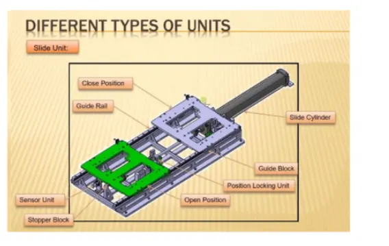
Q6-What are the points you need to consider while designing a Slide unit?
A6-The sliding unit is a complex unit, thus when constructing it, keep the following points in mind:
The two end limits must be designed properly with sensor to detect the position.
Shock absorbers are used to be both extended and retracted conditions.
Stroke length must be selected based on the available space.
Reverse stroke of 10 mm to be considered in both forward and retracted conditions