Week 7:- Base Unit Design Challenges 1
1. BASE UNIT: The Base unit is the first part of a BIW fixture where all other units are mounted i.e. Pin units, Clamp units, retractable pin units, etc. Apart from this, Valve Banks, Trunken channels are also mounted to the base units.
Typical parts of a Base Unit are as follows:
- Base Plate: It is a thick plate with thickness varying between 25 to 40mm in general that has drilled holes to mount the other units.
- Pedestal: It is a standard component that is welded onto the Baseplate and Floorplate to connect both with each other.
- Floor Plate: It is a thick plate that is grouted to the ground by drilling holes in it to fix the fixture Base unit.
- Trunken Channel: It is a standard duct that has all cables from the pneumatic units (cylinders, clamps, pins) accumulated through it.
- Valve Box: It is the combination of all solenoid valves that has a common inlet and outlet to allow the airflow to the pneumatic components to maintain the pressure needed to operate.
- Eye Bolt: It is used for mounting the lifting the hooks to transport Base unit from one station to other.
2. The points that are to be considered while designing a Base Unit:
- Base Unit should cover all other units within its periphery without any clashing of components and be easy to use all units.
- It should always be designed with respect to Body Coordinate System (B.C.S)
- It should be drilled with Datum Holes that should be in 100mm pitch in line.
- The number of holes that are to be drilled should depend on the Size of the Base Plate.
- Datum holes that are to be drilled should be at nominal values from the Baseplate and should be in multiples of 50 or 100.
- A minimum distance of Datum holes from units should be 100mm.
- Datum holes should be covered with a cover plate.
3. DUMP UNIT: This unit is used when we have some geometrical constraints for panel fixtures. Then in such cases, we used dump units. A dump unit is complex to design, as it contains less space and has to adjust the units in such less space. It has a Dump Cylinder that is used for clamping the other units in such confined space.
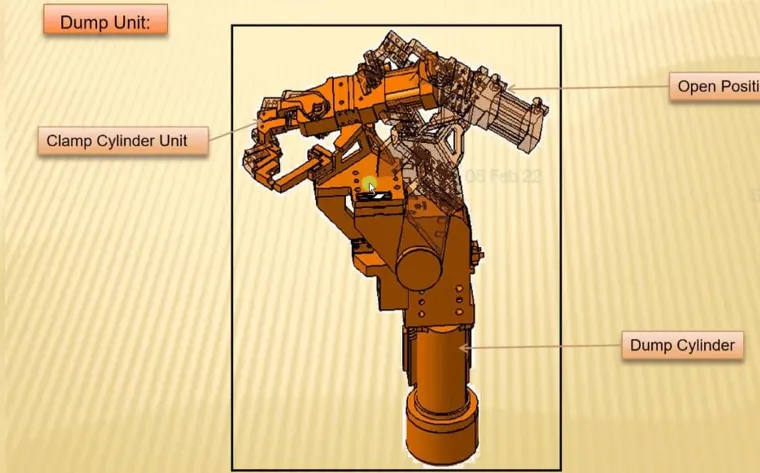
4. The points to be considered while designing a Dump Unit:
- Designed parts of a Dump unit should be of a small size than normal clamp units as the space available in the Dump unit is less.
- The Riser and the Blade used in dump units should be of high bearing load capacity as it has to bear the load of heavy dump cylinder and all other units mounted on the Dump unit.
- While designing the parts of a dump unit, the condition of the dump unit should be an open condition as in open condition we can consider the maximum available spaces for other units.
- Dump cylinder is usually of either clamp type or hinge type
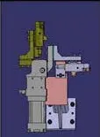
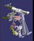
(Clamp Type-Dump unit) (Hinge type- Dump unit)
5. SLIDING UNIT:- It is used to give multiple constraints to the panel and all other units i.e. positioning the position of fixtures, panels, weld guns, units, robots for further operations like Hardened guideways, LM guideways. It consists of the following parts:
- LM guideways
- Linear cylinder
- Front-Rear stopper
- Front-Rear shock absorber
- Proximity/reed switches with sensors
- Bellows for protection at the two ends.
Sliding units are classified into two main categories:
| Based on Prime mover | Based on application |
| Hydraulic/pneumatic slides | Horizontal slide |
| CNC slides | Vertical slide |
| Manual Slides | Angular Slide |
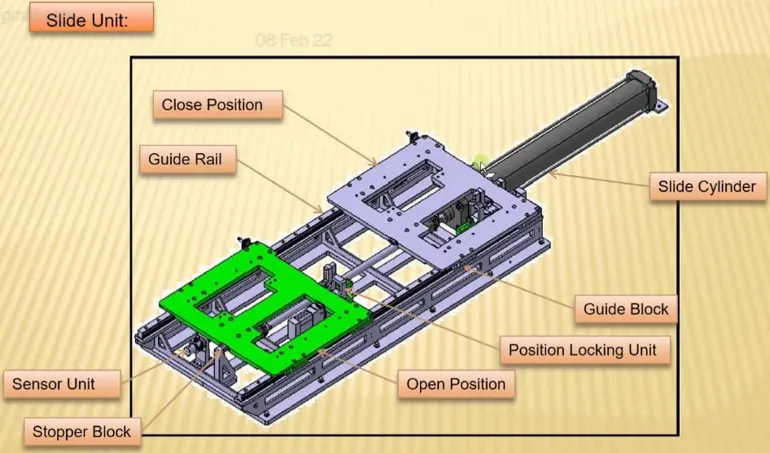
6. The points that need to be considered while designing a Slider unit:
- LM guideways are preferred over hardened guideways due to the coefficient of friction being less.
- Reverse stroke of 10mm to be considered during and forward and backward sliding movement.
- Cylinders and LM guideways to be designed for both loads and strokes.
- LM guide rail should be of standard length and greater than stroke length.
- Mechanical hard stop to be considered for both forward ad backward movement.
- A shock absorber should be installed for both forward and backward movement to reduce impact load.
- Both side extremities for the Sliding unit should be sensed with proximity sensors.
- A shock absorbed should be mounted perpendicular to the pivot at the mid point of sliding guide rails within +/- 5 degrees.