Week-6 : Turbocharger Modelling
AIM
* To listdown different TC and locate examples from GT power.
* To explore tutorial 6 and 7.
* Plot operating points on compressor and turbine maps.
* To explain in which application VGT turbine is beneficial.
* To explore example-diesel VGT EGR and understand the modeling part.
INTRODUCTION
Since this assignment aims in understanding the turbocharger let us start by having an understanding about what are turbochargers and what is their purpose. Turbochargers are mechanical devices that force inducts the intake air into the cylinder so that for a given amount of air more fuel can be burnt and hence better compression ratio, performance of the engine is obtained. Tubochargers are a combination of a turbine (which is usually reffered as turbo) and a compressor, it is the compressor which compresses the incoming air before it is inducted into the combustion chamber. Turbine part of the turbochargers drive the compressors, exhaust gases from the exhaust port is used to rotate the turbo which inturn runs the compressor and hence compression of the air takes place.
There is another mechanical device which does the same thing as that of the turbochargers i.e, compressing the intake air and it is called as superchargers. As stated above in turbochargers the compressor runs with help of turbo, instead of turbo if the compressor is run using the output power from the engine then it is called as supercharger. Most commonly used are turbochargers rather than superchargers.
There are different types of turbochargers which are briefly disscussed below,
--> Single turbos - These are the most commonly used turbochargers and these are one for which by differeing the size of the turbo completley different torque characteristics can be achieved. Large turbos provide higher level of top end power, while the smaller ones can spool faster and provide better low end power. Using these turbos in smaller engines for better performance is very much cost effective. Problem with single turbos is turbo lag. We know that it is the exhaust gases from the engine which runs the turbo which inturn runs the compressor. More the exhaust gases much better the turbo will rotate and hence compression of air inside the compressor happens quickly. In idle conditions and in low range speeds the less exhaust gases are produced and hence the turbo will rotate slowly and hence there is a lag which is often reffered as turbo lag.
--> Twin turbos - As the name suggests it is 2 turbos. One turbo works at low rev (lower rpm) and the other works at higher rev and hence this type of turbos can operate effectivley over a wide range of speeds also it reduces the turbo lag. These type of twin turbochargers are found in v6 and v8 engines. Disadvantage of these type of turbos is that it increases the cost and moreover there is complexity since more space is needed to accomadate the 2 turbos.
--> Twin scroll turbos - Twin scroll turbochargers require divided-inlet turbine housing and exhaust manifold that pairs the correct engine cylinder with each scroll. Suppose we have a 4 cylinder engine in which the firing order will be 1 3 4 2, in this case the exhaust from cylinder 1 and 4 might feed one scroll while exhaust from cylinder 3 and 2 will feed the second scroll. This kind of arrangement provides more efficient delivery of exhaust gase energy into the turbine and helps provide denser, purer air into the cylinder. Since this system has the divided housing of the turbine and exhaust manifold and the complexity involved the cost will be higher.
--> Variable geometry turbo - This type of turbos have a ring of aerodynamically shaped vanes in the turbine housing at the turbine inlet. The vanes rotate to vary the swirl of gases enetring and also to vary the cross-sectional area. These internal vanes alter the turbos area-to-radius ratio to match the engine speed. At low rpm the A/R ratio decreases as a result velocity of the exhaust gases enetring into the turbine vanes increase and this spools up the turbo to run faster at low rpms. On the other hand at high rpm the A/R ratio is increased which allow more gases to enter the turbine. Main advantage of VGT is that it can reduce the turbo lag and second we can achieve what a twin turbo achieves using aerodynamic vanes on a ring.
--> Electric turbochargers - In this a electric motor is used to run the compressor of the turbo from start of engine till the low rpm range once the engine attains high rpm the turbo gets kickstarted and it runs the compressor. Main advantage of this type of turbochargers is that the turbo lag can completley avoided. The electric motor comes with a cost also the cooling of electric motor needs to taken care as far as reliability is concerned.
* GT-suite provides certain examples that model turbochargers some of them are disscussed briefly,
If we go through Examples/Engine_1D_Gas_Exchange_Combustion/Boosting we can find some examples pretaining to turbochargers and superchargers.
1. Compressor Turbine-Flow : This example is a simple demonstration of a turbocharger simulation that calculates the steady state conditions of a flow network consisting of a compressor, turbine, turbocharger shaft, piping and imposed boundary conditions.
2. CompressorTurbine-maps : This model file demostrates the option of using simulation preprocessing to pre-process turbocharger maps for use in other model files without running an engine simulation.This model file demostrates the option of using simulation preprocessing to pre-process turbocharger maps for use in other model fies without running an engine simulation.
3. PressureWaveSupercharger-Hyprex-Engine : This example demonstrates a Hyprex pressure wave supercharged SI engine with a semi-predictive intercooler. The model runs at steady state engine speeds with wide-open throttle (WOT).
4. PressureWaveSupercharger-Hyprex-FlowBench : This example shows a Hyprex pressure wave supercharger test rig configuration. The model calculates steady flow conditions.
5. SimpleTurbineCompressorTwoStageMeanValue : Example illustrating use of simple compressor and turbine components which do not require maps.
6. DI_2_Stage_Controls : This example represents a fast-running 6-cylinder diesel engine with 2-stage turbocharging. The engine cylinders have been represented by a single mean value cylinder, and the intake and exhaust system have been greatly simplified. With a simplified engine representation, this model runs very fast and is ideal to study the turbocharger matching and control strategy.
--> To explore tutorial 6 and 7 :
* Since we are interested in understanding about turbochargers and modelling the same let us start with tutorial number 7 because this tutorial gives step by step procedure that should be followed while modelling a turbocharger.
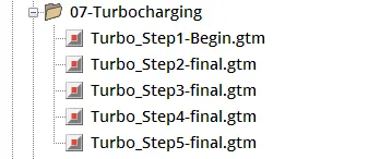
* A snip of the different step available under tutorial number 7 is shown below,
* Turbo_step1 : A snip of the project map is shown below,
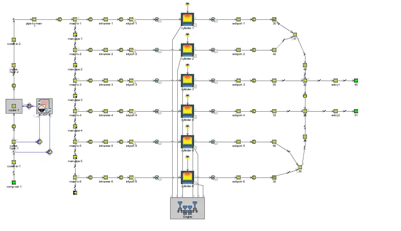
* In this instead of a compressor template a end environment is used which represents the compressor outlet and for turbine part instead of using a turbine template two end environments are used which represents two inlets of the turbine as shown in below snip's.
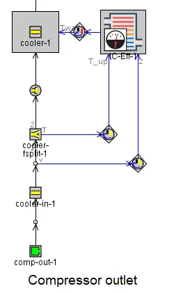
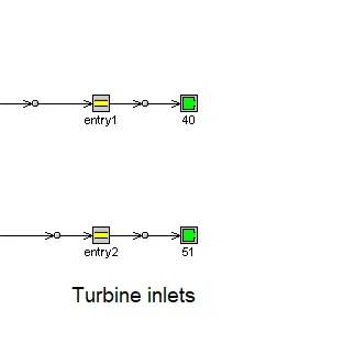
* The main purpose of using this simple modelling technique is that it helps in finding the root cause of problem if the engine performance predictions from the simulation does not match with experimental data. Adding compressor and turbine into the engine model complicates the system and hence it becomes difficult to find the problem if any.
* Turbo_step2 : A snip of the project map is shown below,
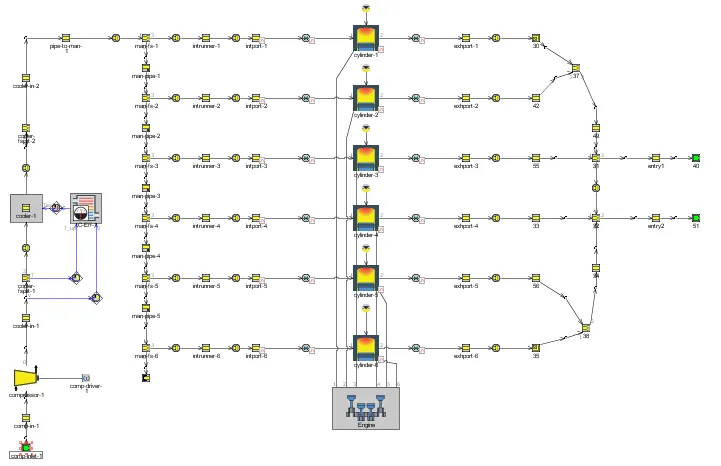
* This can be considered as second step in turbocharger modelling, in previous case an end environment is used to represent the compressor outlet, but in here that compressor outlet end environment is replaced by a compressor template. On turbo side the end environment representing tubine inlet is kept intact.
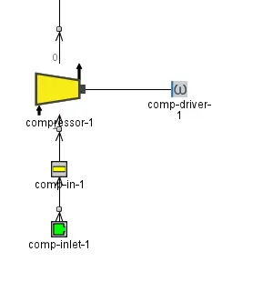
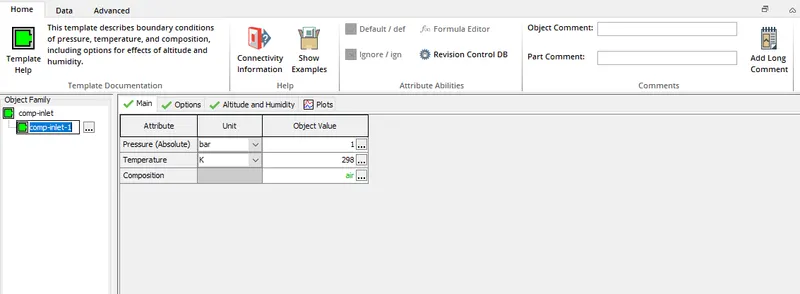
* First an end environment template named comp-inlet-1 is added, which represents the environment from where the air is taken into the compressor. A pressure of 1 bar and temperature of 298 K is set for the comp-inlet-1 with composition of fluid set as air.
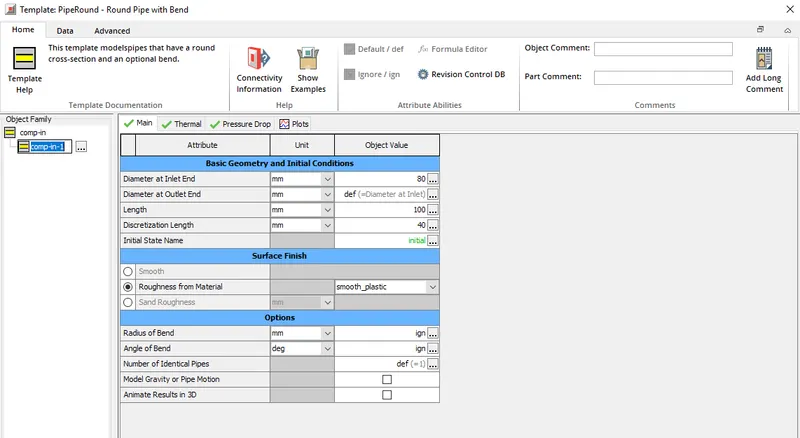
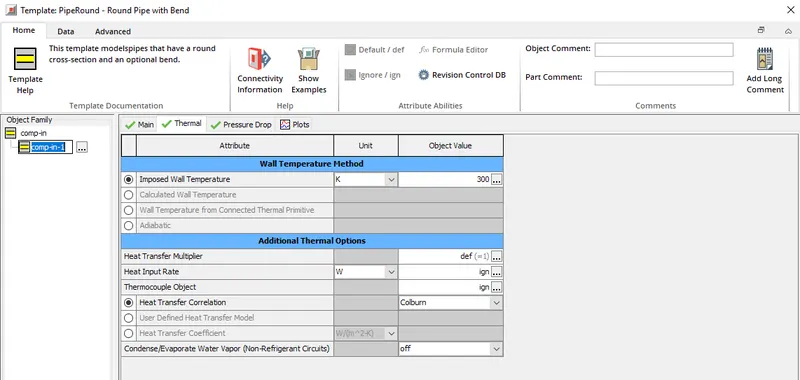
* Next comes a inlet pipe into the compressor, a circular pipe with inlet and outlet diameter of 80 mm and length of 100 mm is used. Wall temperature of 300 K is imposed and colburn model is set to compute the heat transfer coefficient.
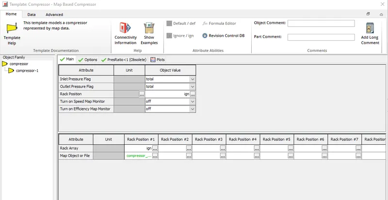
* A compressor is placed on the project map from the templates library. under the main folder the inlet and outlet pressure flags need to be set. The pressure flag set should match with the type of pressure measurement the turbocharger manufacture used.
* For compressor's usually both the inlet pressure and outlet pressure is measured as total pressure and hence this option can be set for inlet as well as outlet pressure flag.
* Next important thing is setting up the rack array and corresponding compressor_performance_map. Different rack arrays are defined when the compressor is of variable geometry which is very rare. Most commonly used compressor's are fixed geometry and hence rack array can be ignored and a single compressor_map can be defined
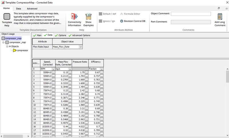
* Compressor_map reference data include a corrected speed, corrected mass flow rate, pressure ratio and efficiency. These data set is defined a range of corrected speed and this is provided by the turbocharger manufacturer. A snip of the same is provided below,
* Under the main folder we can define the type of compressor and reference temperature and reference pressure, snip is provided below
* Attributes under the options folder are left as default.
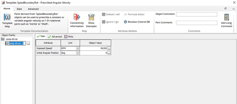
* Since in this approach a turbocharger is not modelled and hence there is no shaft connecting from turbo to compressor a speed needs to be imposed on the compressor and this is achieved using comp-driver-1. Comp-driver-1 is a part derived from speedboundaryrot and it is used to prescribe a constant speed on 1-D rotational parts.
* A speed of 96200 is set under the main folder and it is this speed which is imposed on the compressor to rotate.
* Turbo_step3 : A snip of the project map is shown below,
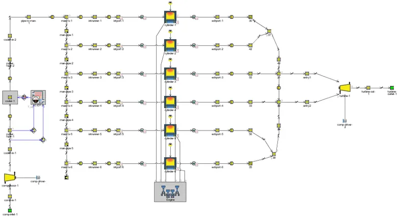
* This model is different from the step_2 by addition of a turbine template, in step_2 only turbine inlets were defined but here a turbine template along with other additions are used.
* There are 2 entry's entry 1 and entry 2 through which the exhaust gases enter into turbine, exhaust from cylinder 1-3 is passed into entry 1 and exhaust from cylinder 4-6 is passed into entry 2.
* A snip of the turbine along with associated parts is shown below,
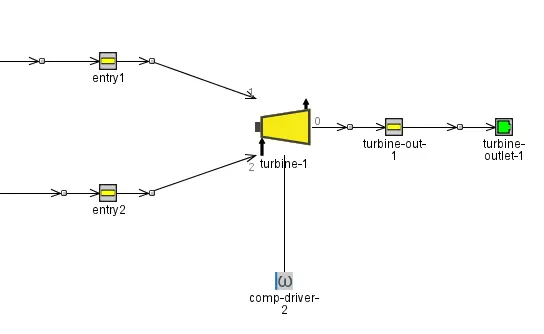
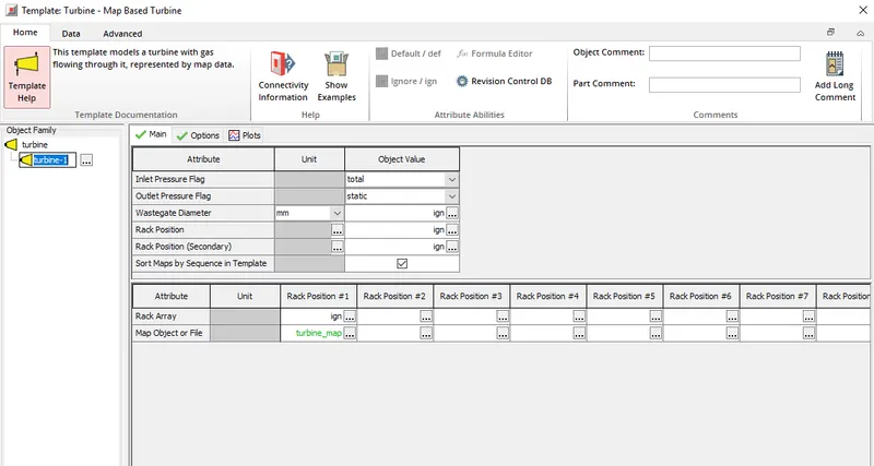
* Tubine template is added to the project map from templates library, inlet pressure flag and outlet pressure flag needs to be set and this should match with the pressure measurements turbocharger manufacturer used while developing the turbocharger. For turbochargers generally inlet pressure flag is set to total pressure and outlet pressure flag is set to static pressure.
* Next important thing is setting up the rack array, if the turbine is of fixed geometry then rack array is set to ignored and only one turbine_performance_map is defined.
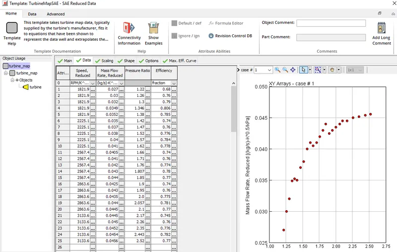
* If the turbine is variable geometry type then there will be different rack positions and for each rack position there will be separate turbine_perform_map. Turbine_performance_map data consists of corrected speed, corrected mass flow rate, pressure ratio and efficiency. Snip of the same is provided below,
* Since the task of the turbine is to power up the compressor it is must that both rotate at same speed. This step of the turbine model is incomplete, meaning when turbine and compressor is connected by means of a shaft then it will become complete, so to achieve same speed in the absence of a shaft a comp-driver-2 part is used and it is derived from Speed BoundaryRot, a speed of 96200 rpm is set and this speed is imposed on the turbine.
* Even for compressor the same object with a part name comp-driver-1 is used and same speed is imposed.
* From turbine the exhaust gases are vented out to atmosphere through an end environment. From turbine exhaust through a pipe the exhaust gases are vented, the pipe is modelled as a pipe with circular cross-section with inlet and outlet diameter of 60 mm and length of 100 mm, as far as thermal boundary conditions are concerned a temperature of 700 K is set and material of the pipe is set to steel along with its emissivity, wall thickness also the external convection temperature is set to 350 K and external convection coefficient is set to 15 W/m^2.K
* Hence the inbuilt wall thermal solver solve's for the temperature of the wall, heat transfer coefficient is determined with the help of colburn model.
* Turbo_step4 : This is same as that of Turbo_step3, if the average power of turbine and compressor in step2 and step3 are good then no need to proceed with turbo_step4 else we can calibrate turbo_step4 by changing the compressor and turbine efficiency mutipliers.
* Turbo_step5: The snip of the project map is shown below,
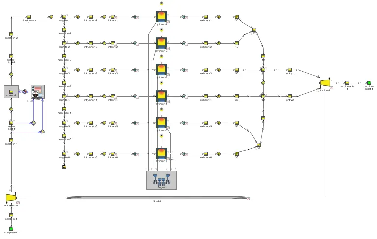
* This can be stated as a complete model since the turbine template a well as compressor template is connected via a shaft.
* Shaft turbo template is taken from template library and pasted on the project map.
* The initial speed of the shaft is defined, it will be better if we define the shaft speed much closer to steady state opearting speed so that shaft speed converges in reasonable number of cycles.
* Initial speed of the shaft is set to 96000 rpm and shaft moment of inertia is set to 0.0005 kg-m^2.
* Since shaft template is added the comp-driver part can be removed from both compressor and turbine.
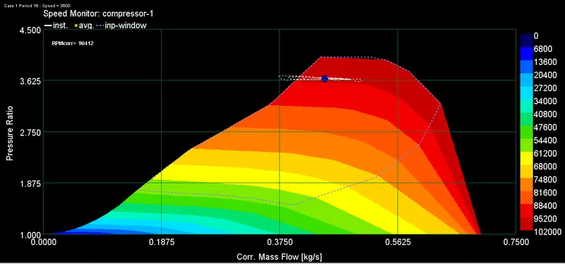
* The above turbo_step5 model is run at a speed of 3600 and operating point on the compressor speed map as well as compressor efficiency map is noted.
Speed map:
Efficiency map:
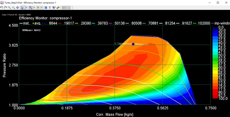
From the above two contour plots it is clear that the engine operating point is at red band region and hence it is a satisfactory result, Let us run the simuation at 4600 rpm and let us check the where does the opearting point lie.
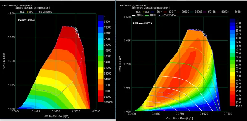
* At 4600 rpm the operating point is at the bounds of the above contour plots which indicates that the compressor is at its peak operating condition and this is not good since chances of mechanical failure is more.
* Not only the speed of the engine but the mass of fuel injected per cycle, altitude at which the engine is operating are different factors that affect the performance of compressor, but end of the day wether its compressor or turbine the operation has to be within the bounds of the above contour plots.
--> Applications at which variable geometry turbo is beneficial :
* Variable geometry turbo is used to overcome the turbolag. In fixed geomtery turbo area-to-radius ratio is fixed. At idle speed and low speed conditions the exhaust gas coming out from the engine is low and hence this is not enough to run the turbo at higher speeds, if turbo runs at higher speed then compressor can compress air quickly, so at lower speed and idle engine conditions there will be some delay for the compressor to compress the air and feed it to the engine cylinder this is known as turbolag.
* To overcome turbolag VGT's are used, VGT consist of a set of blades the A/R of which is controlled using actuators. When engine is at idle and low speed the A/R ratio is decreased and hence exhaust gases are fed with high velocity into the turbine blades and hence the turbine rotates fast. At high engine speeds the A/R ratio is increased so that more gases enter the turbine and hence the turbolag is completley avoided.
* In passenger cars because of turbo lag it effects the driving comfort, but if a VGT is used this driving comfort need not be compromised.
* There are other approaches such as twin turbo, e-turbo used to overcome the turbolag but consumes more space to accomadate two turbo's in case of twin turbo and a motor in case of e-turbo and hence VGT's are a good to go option.
--> To explore diesel EGT VGR model :
* In GT-power example case we can find a diesel_EGR_VGT model the path to access this example case as follows: Examples/Engine_1D_Gas_Exchange_Combustion/Diesel/Diesel_VGT_EGR
* This model has an EGR unit with intercooler, VGT turbocharger. Since this assignment is regarding turbocharger modelling let us concentrate on VGT turbocharger used in the model EGR unit and its modelling will be disscused in detail in upcoming assignments.
* Project map of the Diesel_EGR_VGT model is as shown below,
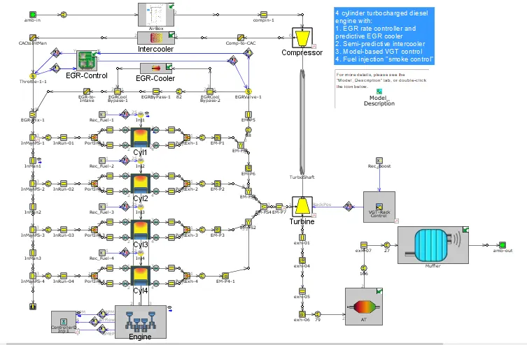
* The turbine used in this geometry is of variable geometry hence different rack array's need to be defined and for each rack position a definite turbine_performance_map should be defined.
* Since this is a 4 cylinder engine the exhaust from all 4 cylinders enters into turbine. Inlet pressure flag is set to total pressure and outlet pressure flag is set to static.
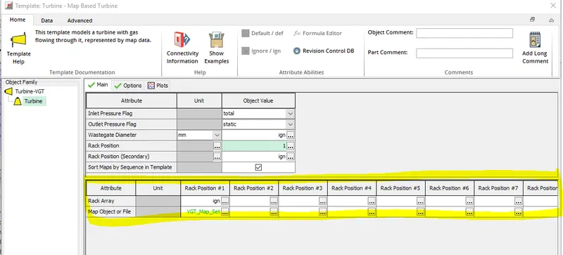
* For a variable geometry turbo the rack array can be defined in two ways. First one we can define different rack positions in themain folder itself. If this way of defining the rack position is followed then the below table will be filled with rack_position and corresponding turbine_performance_map.
* Other way of defining the rack position in VGT is to define a VGT_map set for Rack position #1 in the above table. If we open the object value VGT_Map_Set we can define the rack position and performance_map as follow,
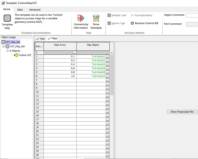
* Above rack array starting from 0.1 to 1.0 corresponds to 10% to 100% opening of the outerblades which are controlled through actuators and corresponding object value Turb-Rack01 to Turb-Rack10 is the defined turbine_performance_map.
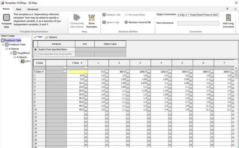
* The rack position is controlled by an actuator which recieves signal from the control unit. Control unit controls the boost pressure by adjusting the rack position so as to achieve the target boost pressure.
* The control unit recieves two signals one for engine speed and another one for fuel injection rate, these are the independent X, Y values of the RLT dependence table for which Z is the boost pressure and it is the dependent variable. A snip of the table that control unit uses is shown below,