Mid-surface extraction and deploy shell mesh for a Hood Component
MESHING OF HOOD CHALLENGE
AIM:
To perform pre-processing operations including geometry cleanup, mid-surface extraction, and shell meshing on the given automobile hood model.
The meshed FE model is then checked for quality criteria and refined accordingly.
PROCEDURE:
1. SETTING UP THE MODEL
- CAD geometries exported from many Softwares like .prt, .stp, .iges, .asm, .catpart, .sldprt etc. can be imported using the Import geometry command
- To visualize the cons in Hypermesh, the Topo module is selected and the properties of each feature can be changed in the toolbar at the visualization tab
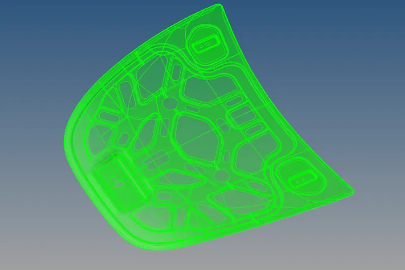
Fig: Topo of CAD model
- In the model tree, the entire model is subdivided into four components - the outer extract, inner extract, latch, and hinge.
- Since each of these models are not interconnected and have a different thickness and property id, then it is advisable to extract the mid of each component individually and mesh each separately.
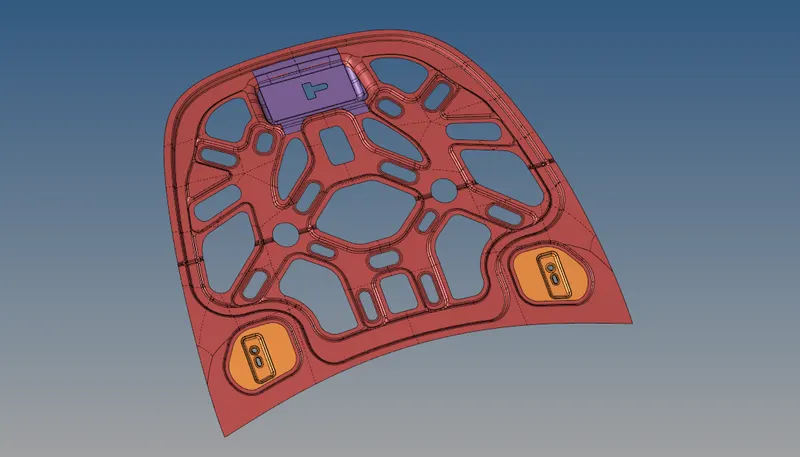
Fig: Sub-components
2. GEOMETRY CLEANUP & MID-EXTRACTION
- The model is cleared for geometrical errors and extracted for mi-surface using the auto cleanup command.
- To specify the mid extraction parameters: geom - auto cleanup - edit parameters
- The cleanup tool is also capable of extracting the mid surface of the component. edit parameters - basic - extract mid-surface
- This feature is also capable of geneating a mid-mesh where the model is meshed without the creation of a mid surface. However having the mid is advisable in case the meshed elements have to be removed.
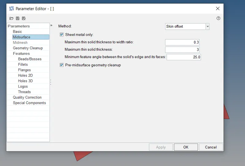
Fig: Mid extraction using auto cleanup
- The type of extraction method is specified as 'Skin offset'. In case if the model consists of multiple components, then the max thin solid thickness value can be specified so that hypermesh only extracts those components that fall within this range. In our case since this is a fairly thin component the max value is set as 3 and the avg thickness of each component is measured to be 2.5 mm.
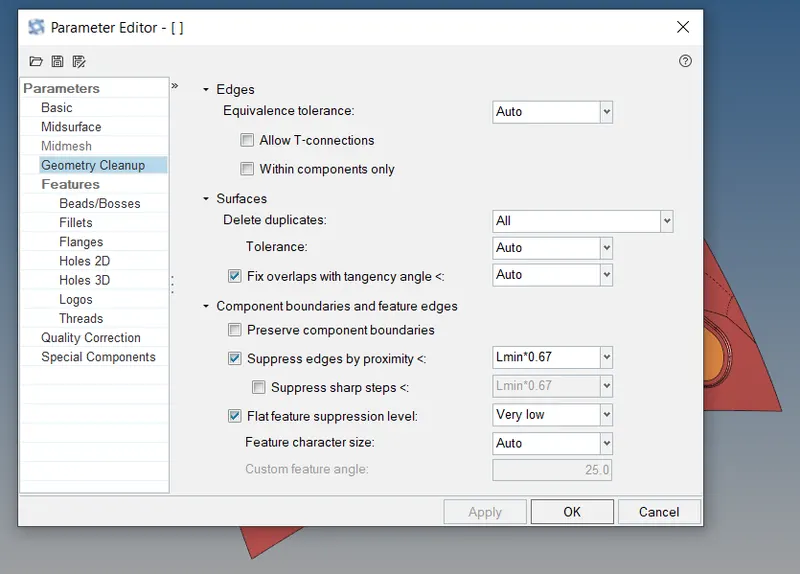
Fig: Geometry cleanup
- Similarly while extracting the component for mid-surface, the geometry is also automatically cleaned up. The parameters of the cleanup is also specified in the parameters window and other features like tolerance, duplicate/old surfaces, etc are also specified.
- The auto cleanup is performed on each component.
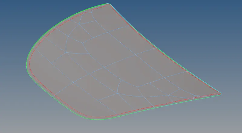
Fig: Mid of outer extract
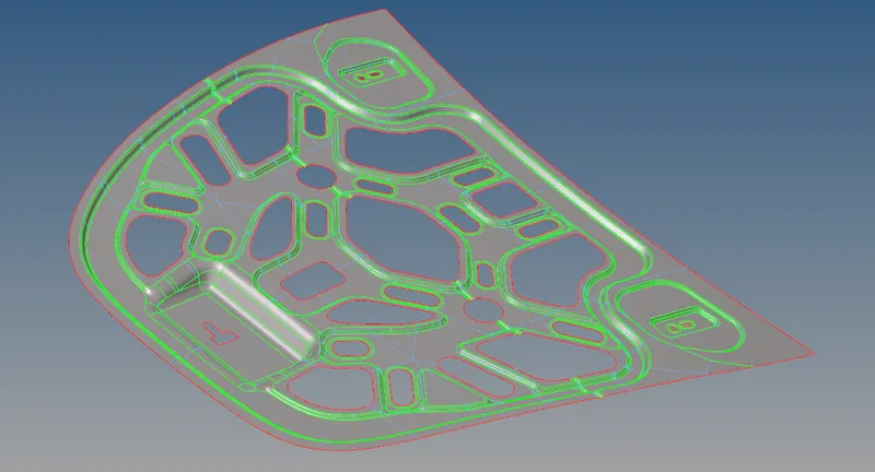
Fig: Mid of inner extract
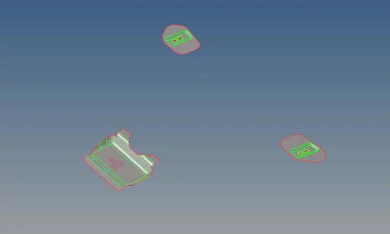
Fig: Mid of latch and hinge
- While performing the auto cleanup process, Hypermesh if specified automatically cleans the geometry of the model. The cons are defeatured so that a smooth mesh flow can be generated later on.
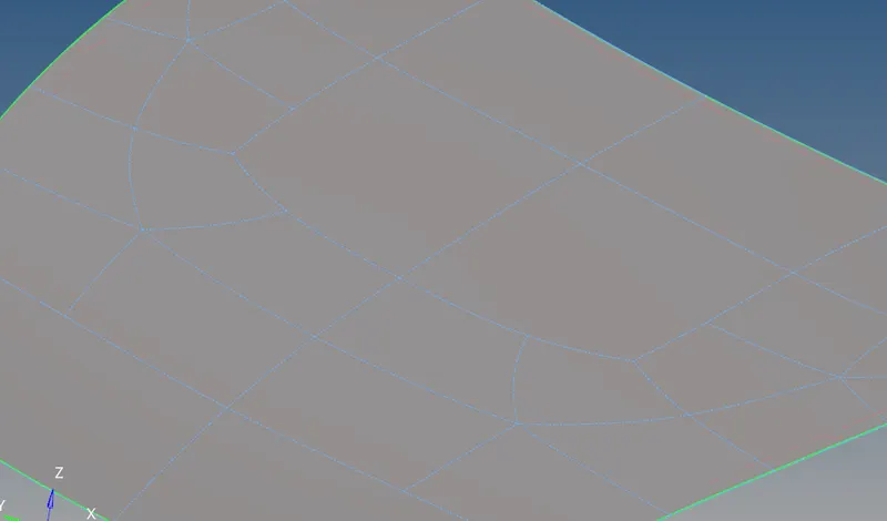 Fig: Defeaturing by auto cleanup
- By default the auto cleanup feature creates two layers of washers around the holes, however, this can be modified into just one layer in the 2D holes menu in the cleanup window (as shown below)
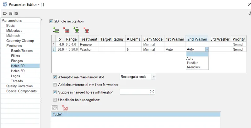
Fig: Washers in auto cleanup
- Hence each hole feature is created with a single layer of washer using the auto cleanup method
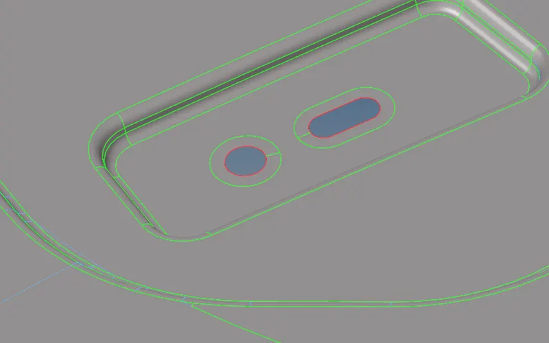
Fig: Washers
- Certain features in the component that are not identified by HYPER MESH as holes cannot be used for creating washers around it. Such features have to be manually extracted for the washer using the quick edit - washer split - offset dist- lines (as shown below)
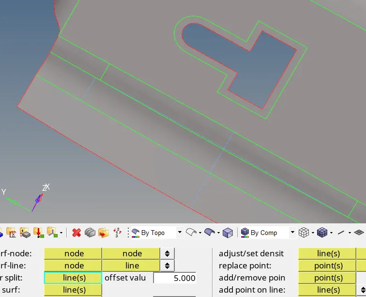
Fig: Washer split
3. ASSIGNING PROPERTY
- After extracting the mid of each component, a property card is assigned to each one specifying the thickness of each component.
- Prior to this a material card has to be created and assigned to each of the property card.
- To create a material card: Materials - steel - Isotropic - MAT1 (which is the material card for isotropic structural materials in optistruct. MAT4 is used in case of thermal analysis)
- Then create a property card and assign the created mat card (steel). Specify each component as a PSHELL comp and assign its respective thickness

Fig: Property card
- The thickness of each of the 4 components are measured using the distance command in geom and specified the same under the property card.
4. SHELL MESHING
- After creating the mid of each part, each can then be meshed seperately.
- To create mesh: 2D - auto mesh - target length =5 - select surface - mesh
- The created mesh can be modified by increasing or decreasing the number of nodes present at the edges.
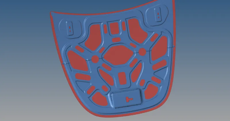
Fig: Shell mesh
5. QUALITY CRITERIA
- The above created mesh is very poor by default with back to back trias, rotating quads, trias at edges and holes, improper mesh flow etc. Hence these defects must be cleared manually.
- Before clearing them, the quality criteria that every mesh element must follow has to be specified.
- This can be specified either in the auto cleanup tab or Preferences - criteria file settings
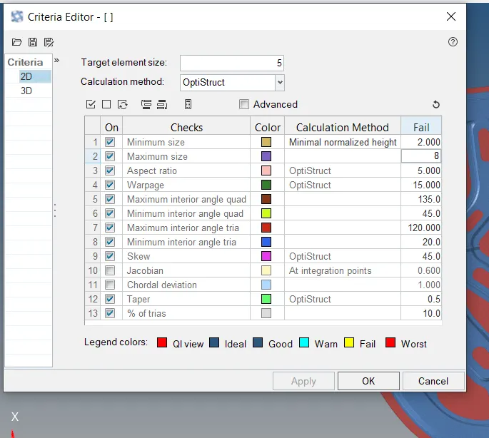
Fig: Quality criteria tab
6. MESH REFINEMENT
- The model is then checked for the above errors using quality index option in the 2D module.
- In the QI, the range is set to worse elements and these elements can be cleared using the cleanup tools present.
- For ex: Elements that fail for aspect ratio because one side is larger to the other over the define ratio can be cleared by splitting up these elements / quads around the edges as shown below
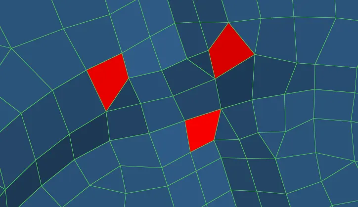
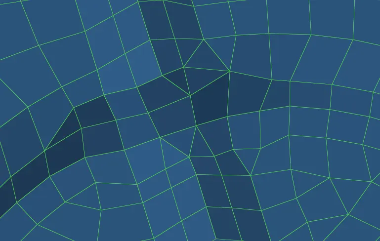
Fig: Mesh refinement
- Similarly, other elems that fail can be cleared either by combining them into a single tria/quad, or split quad/tria elems or by aligning nodes. Nodes can be aligned by: Geom - node edit - align node - select two perfect nodes - select nodes to be aligned
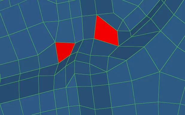
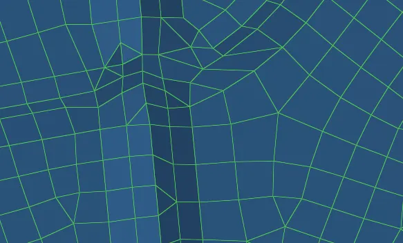
Fig: Cleared elems using split, combine and align nodes
- However the shell meshing failed to capture the fillets present in the model. This can be cleared by remeshing the elems in the fillet and changing the no of elms in the edge this affects the mesh flow in the fillet
- Similarly even after creating washers, element alignment could be misaligned. This can be remeshed and changing the elements at the edges
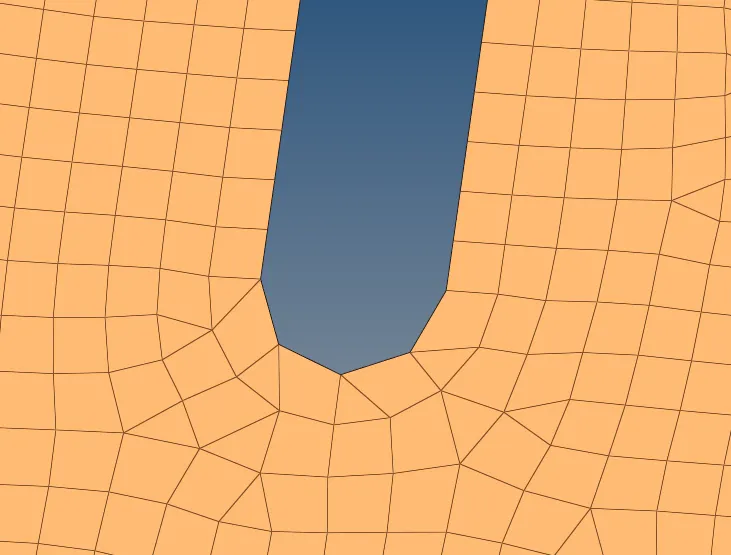
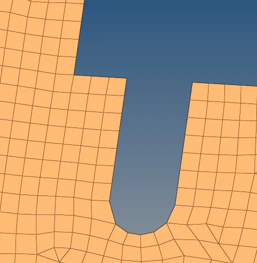
Fig: Washer remeshing
- Similarly, alternatively we can use the check elems feature to check for mesh elems that fail the specified quality criteris. This is much similar to the quality index and can be checked for each individual criterion

Fig: Check elems
- Similarly, if a feature or area in a component that is relatively simple can be reconstructed purely using quad elems then remesh feature can be preformed again with the quad only element checked on
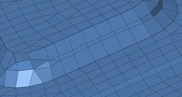
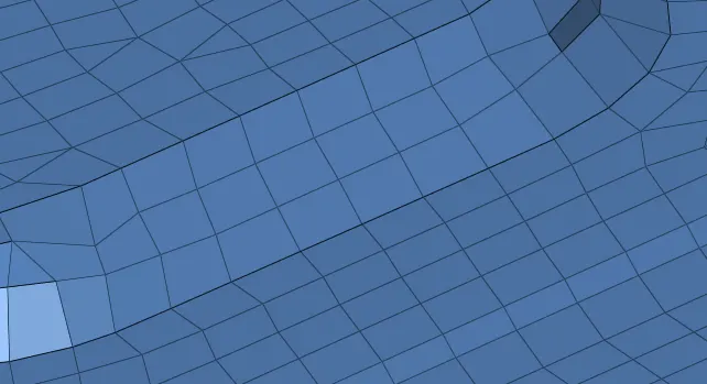
Fig: Remesh using only quads
- Finally to check if the FE has correctly captured the geometry a surface check is done using the below command
- Mesh - checks - elements - comaprison - select elems and surf - set tolerance and run. We will be presented with the following window.
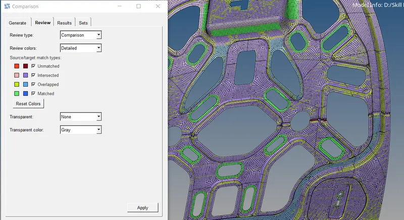
Fig: element checks
- Every element marked red has to be cleared for such errors. To make these elms capture the surface properly the project command is used
- Tools - project - to surf - select elems & target surf - project
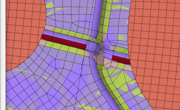
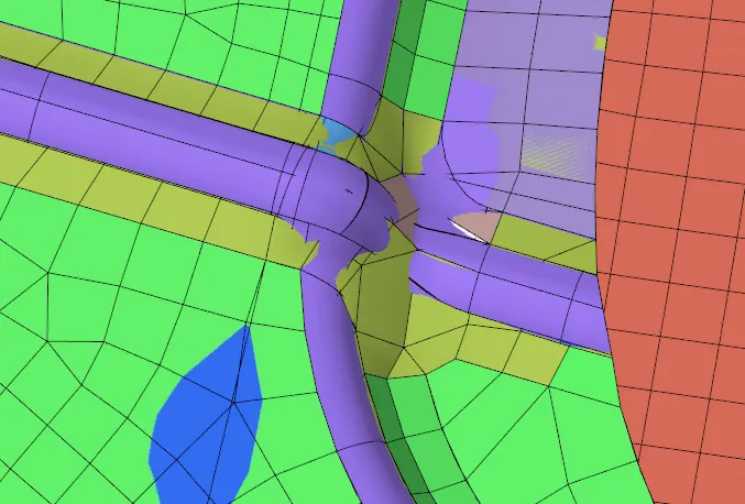
Fig: Elem project onto surface
CONCLUSION:
Hence the entire model is extracted for mid surface and meshed using inbuilt Hypermesh commands.
The final result is shown below.
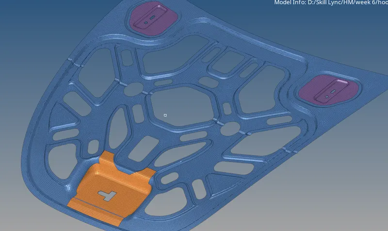
Fig: Mesh refined