Week 6-Meshing of Hood Challenge
WEEK-6 PROJECT
MESHING CAR HOOD ASSEMBLY USING HYPERMESH
OBJECTIVE:
- Import the CAD geometry of car hood assembly
- Clean up the geometry until no topological error is found
- Extract Mid-Surface for the geometry
|
S.NO |
QUALITY CRITERIA |
VALUE |
|
1 |
Minimum length |
2 |
|
2 |
Maximum length |
8 |
|
3 |
Aspect |
5 |
|
4 |
Warping |
15 |
|
5 |
Skewness |
45 |
|
6 |
Minimum Angle Quad |
45 |
|
7 |
Maximum Angle Quad |
135 |
|
8 |
Minimum Angle Tria |
20 |
|
9 |
Maximum Angle Tria |
120 |
|
10 |
Taper |
0.5 |
|
11 |
Tria Percentage |
10 |
ABSTRACT
A Car hood or bonnet is a part which is located at the front end and it covers the engine of the automobile. Its function is to protect the engine. We can easily open and close the hood during repairs or maintenance. Hoods are typically made of the same material as the rest of the body work. This may include steel, aluminium, fiberglass or carbon fiber. However, some aftermarket companies produce replacements for steel hoods in fiberglass or carbon fiber to make the vehicle lighter. In this project we are going to perform geometry clean-up and mesh the hood model according to the given quality criteria using Hypermesh.
INTRODUCTION:
HOOD
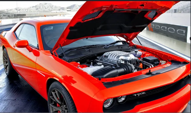
Car hood mainly consists of two parts, inner bonnet and outer bonnet. Inner Bonnet usually provides strength for the engine, battery and other important parts in the front-end of the car. Outer Bonnet provides styling and gives aerodynamic shape to the car body. Various requirements are needed while designing such as safety aspects and the quality criteria.
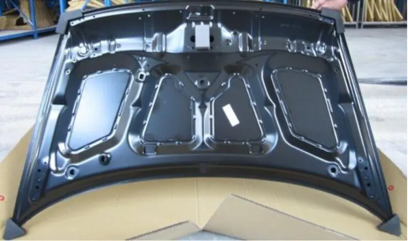
Inner Hood of a Car
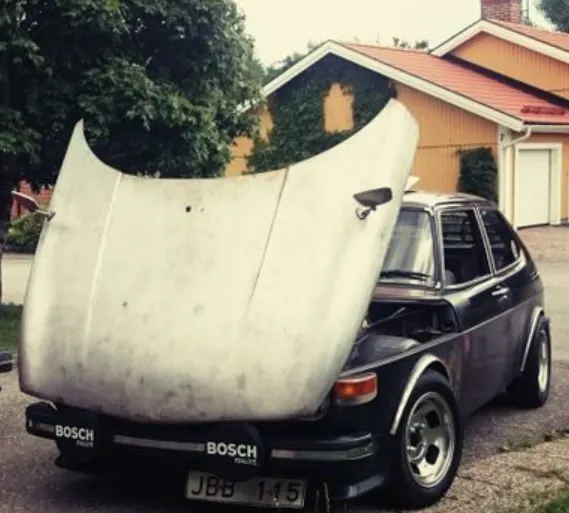
Outer Hood of a Car
QUALITY CRITERIA
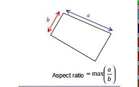
1)Aspect Ratio: It is defined as the ratio of maximum element edge length to the minimum element edge length. The ideal value is 1 but less than 5 is acceptable.
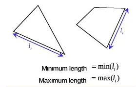
2)Minimum/Maximum element length: It is very important to check this error as it is used for crash analysis check.
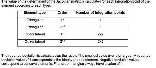
3)Jacobian: It is the scale factor used in the transformation of a coordinated system. The ideal value is 1 but greater than 0.6 is acceptable.
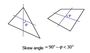
4)Skewness: If the quad element is not a square and has deformation, skewness is defined as 90 minus the minimum angle between the two lines joining the apposite mid sides of the element and similarly for the triangular element it is 90 minus the line between the each node of the opposing mid side. The ideal value is less than zero but 45 degree is acceptable.
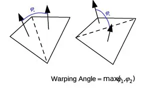
5)Warp Angle: It is defined as the angle between normals of two triangular planes formed by splitting the quad element along diagonals.
PROCEDURE:
Import Geometry:
- Go to File >> Import >> Model/Geometry.
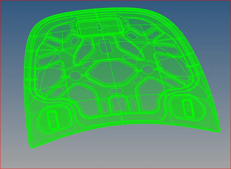
Imported Hood Geometry
- This model consists of 5 solids. Delete all the solids present in it using Delete >> Solid’s option.
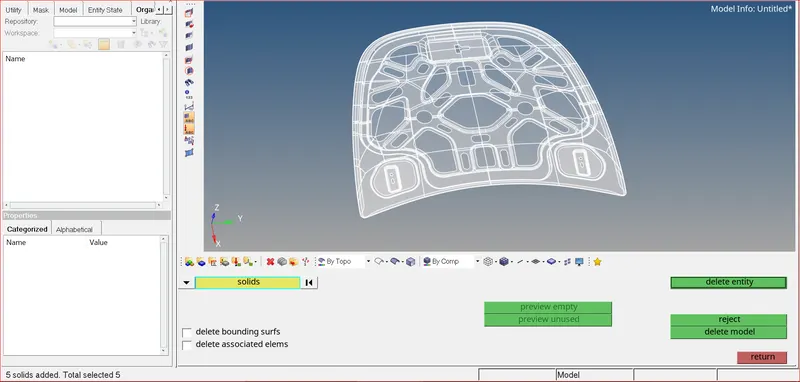
Selecting & deleting Solids
Mid-Surface Generation
- First we need to generate mid-surface in order to mesh the hood model.
- This component consists of 4 parts. 1) outer hood 2) inner hood 3) latch 4) hinges
- I have created mid-surface for each and every component using Geometry >> midsurface option.
- I have used skin offset as an extraction option.
- Select the required surfaces and click extract.
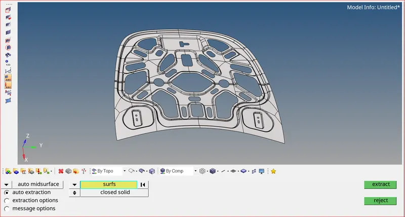
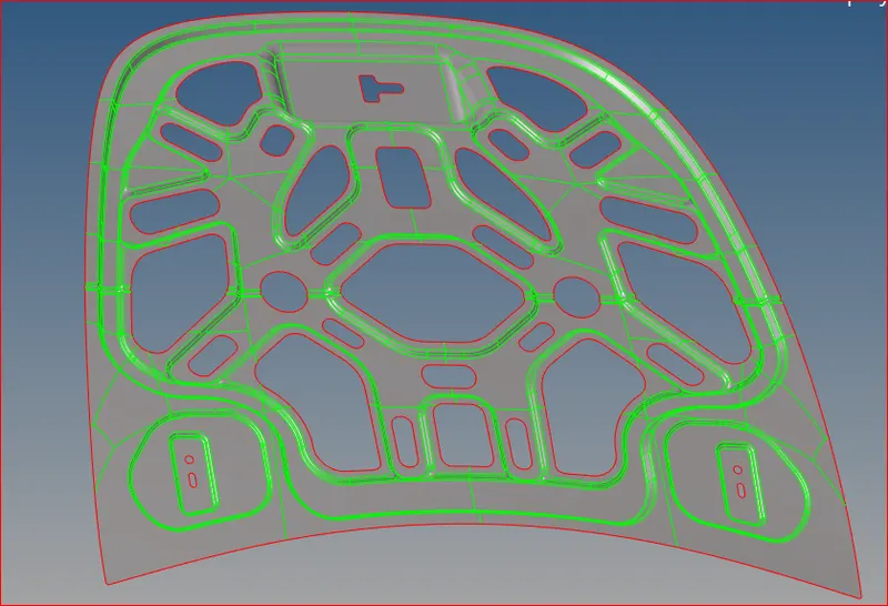
Selecting inner hood surfaces Inner hood midsurface
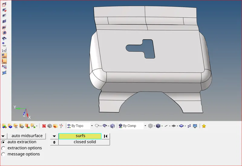
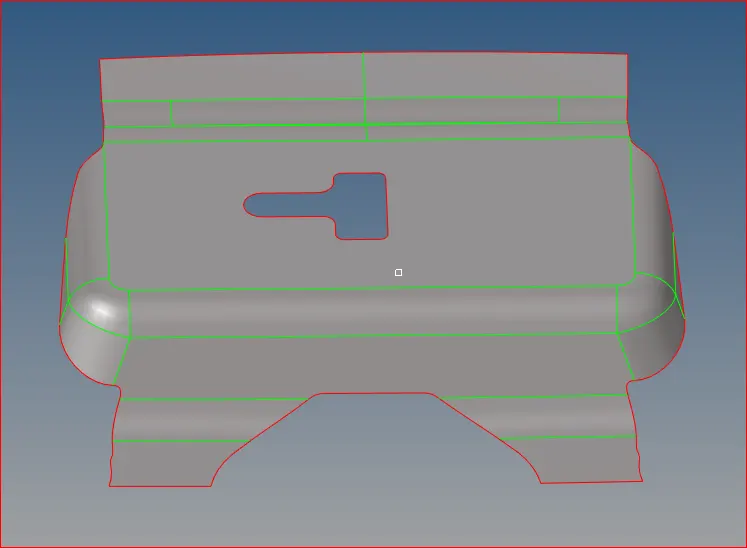
Selecting latch surfaces for mid generation Mid surface generated for latch
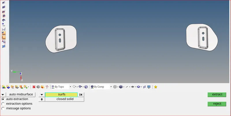
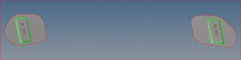
Selecting hinges for mid generation Mid surface generated for hinges
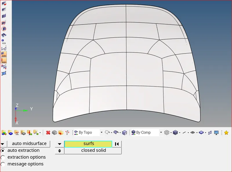
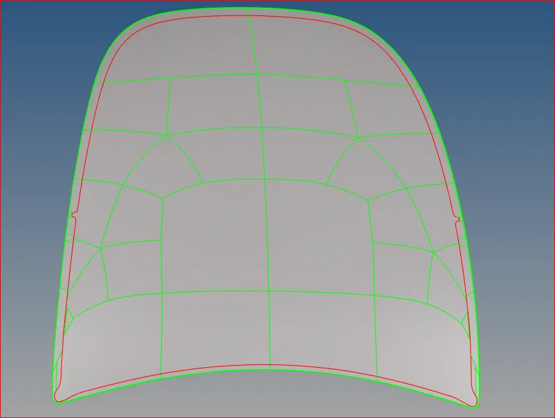
Selecting outerhood surfaces Mid surface generated for outer hood
Geometry cleanup
- After extracting the mid surface for every component, we need to do geometry cleanup so that the mesh generated afterwards will not have any quality issues.
- Use visualization options to see if there are any unnecessary free edges or T- shaped edges (non-manifold).
- For free edges we can toggle them easily using quick edit >> toggle edge option.
- For t shaped edges and irregular surface we can delete them permanently and recreate them with new surface.
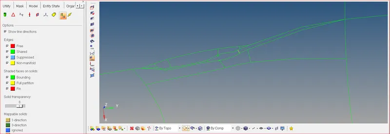
Visualizing surfaces
- Now select all the unnecessary surfaces and delete them. We can also release all the points for better visualization of surfaces.
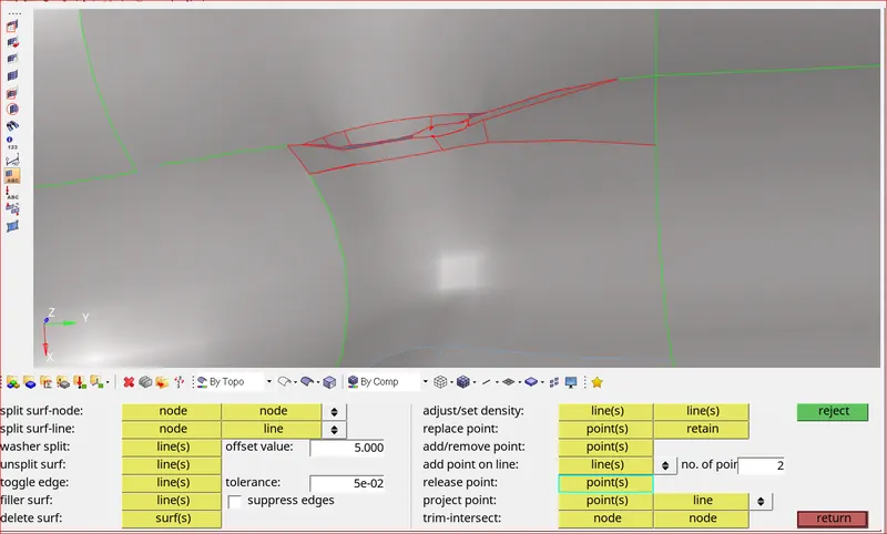
Releasing points on surfaces
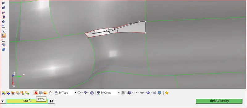
Deleting surfaces
- Now recreate surfaces using Geometry >> spline/filler option
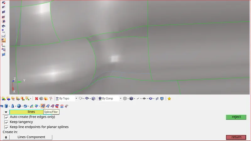
New surface created
- Now suppress all the unnecessary shared edges. We can use Geometry >> edge edit >> select the lines >> use either suppress or unsupress accordingly.
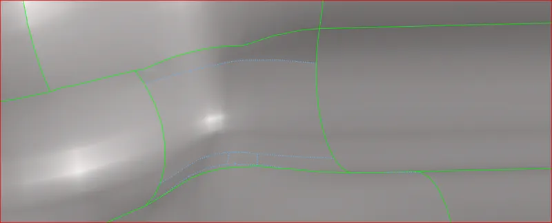
Geometry cleanup done
- Similarily do geometry cleanup for all the surfaces for every component. Geometry cleanup should be done in such a way that the mesh generated afterwards should have better mesh flow and it should satisfy all the quality parameters.
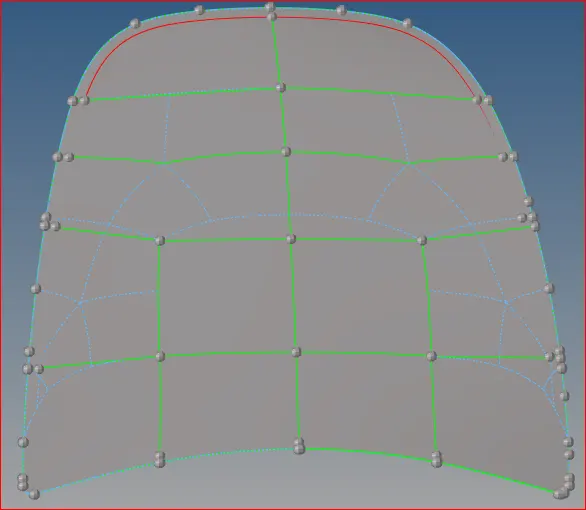
Before geometry cleanup After geometry cleanup
MESHING AND IMPORVEMENT OF THE MESH
- Now mesh each surface separately to achieve better mesh.
- I have used the 'Mixed' (Not Quad) option to generate the mesh for this challenge because we are preparing the model for crash & safety simulations. The quad-only mesh is preferred for durability and structural simulations
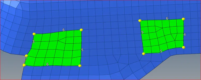
- Opposite trias and rotating quads can be easily eliminated by remeshing the elements in that area.
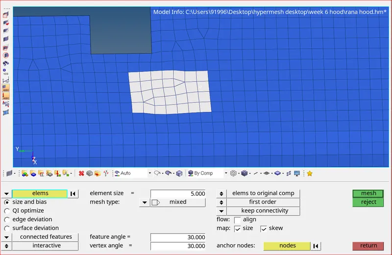
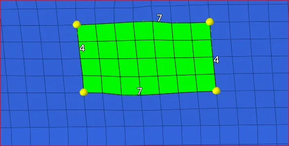
Opposite trias Opposite trias removed
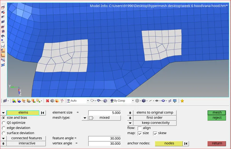
Rotating Quads Rotating Quads removed
- We can align all the nodes in a straight line using geometry >> node edit >> align node option as shown below. This option can also be used for raised edges and kinks.
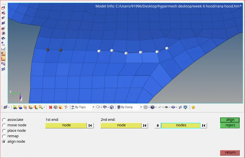
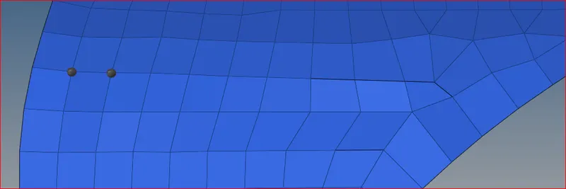
Nodes not aligned Nodes aligned
- We can drag trias out for better mesh using 2D >> quality index >> drag tria element option.
- After dragging the tria element either use smooth option or remesh the area where the tria was earlier, for better mesh flow.
- Element optimize option automatically moves the nodes such a way that the off elements are cleared according to the given quality parameters.
- Using move node option we can control and move the node in any direction.
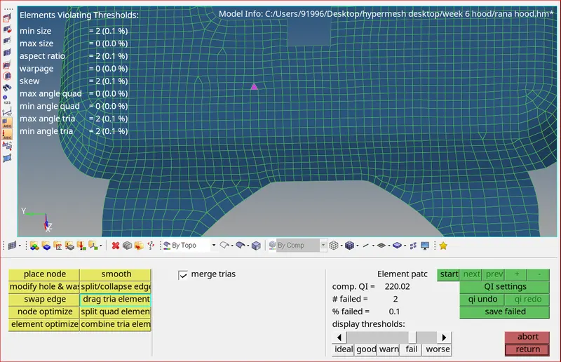
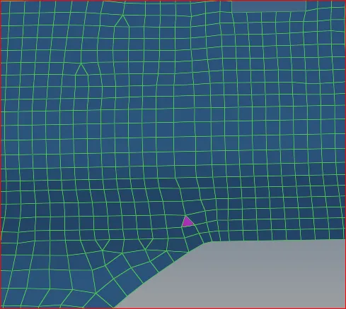
Drag tria element
- Nodes can be projected onto a line using Tools >> project option.
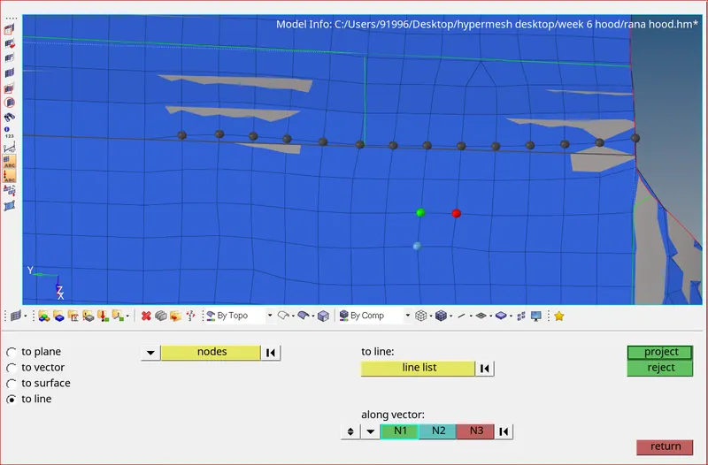
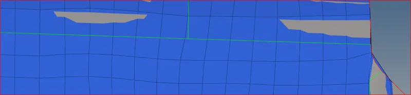
Projecting nodes to line Nodes Projected to line
Creating a mid line at the hemming region
- The minimum length errors in the Hemming regions are acceptable because the hemming region has a very small cross-section when compared to our minimum length.
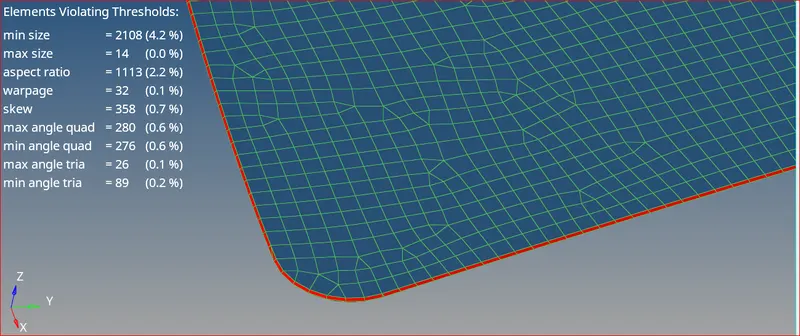
Minimum length errors at hemming region
- If you want to avoid the minimum length error in the hemming, follow the below procedure
- Toggle all the split lines which are all less than the minimum length.
- Go to midline option (Geom → lines → Midline)
- Select the two fillet edges on the hemming portion and create a mid-line.
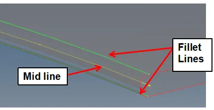
- Then, go to trim with lines option (Geom → surface edit → Trim with lines → with lines)
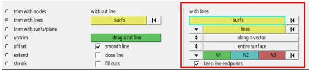
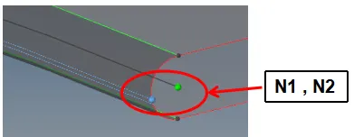
- Define N1 and N2 in that direction, the trim would happen. Nodes can be selected by left click on the line and holding it will turn the line to white, then select where you want to place the N1 and N2 and trim.
- Now, mesh the hemming regions. All the errors are rectified with the creation of mid line.
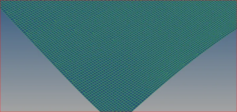
Minimum errors rectified at hemming region
SYMMETRY
- As the inner hood and outer hood are symmetric we can mesh half of its area and reflect the mesh on to the other side. Tools >> reflect >> select all elements (duplicate them before reflecting) >> give direction ( y axis ) >> select base node and then click reflect.
- Reflection should after all the elements are solved according to the quality parameters.
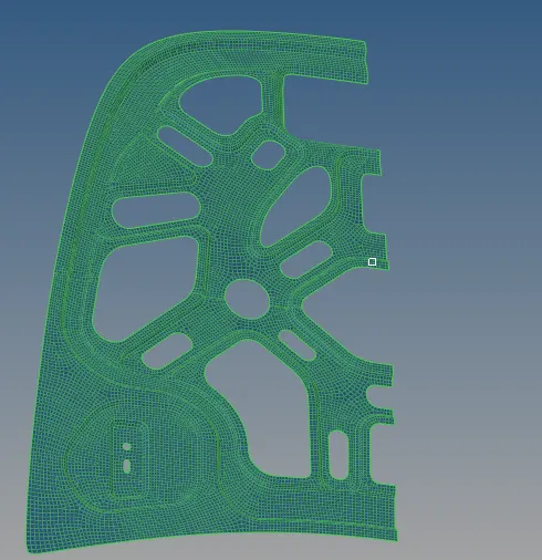
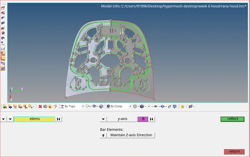
Selecting Elements for Reflection
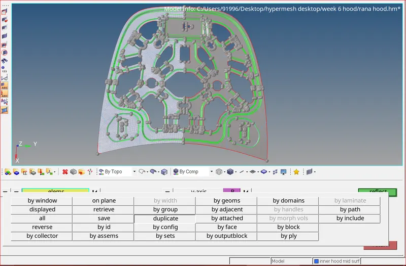
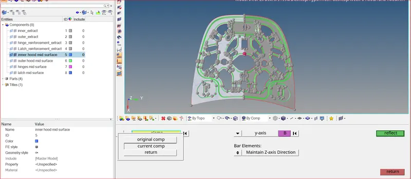
Duplicating, giving direction,selecting base node for elements
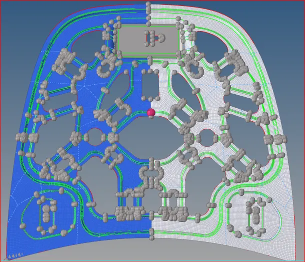
Mesh reflected successfully
- Mesh is successfully reflected on the other side. To check whether the mesh is attached in the middle or not we should use tools >> edges >> elements (select all) >> find the edges.
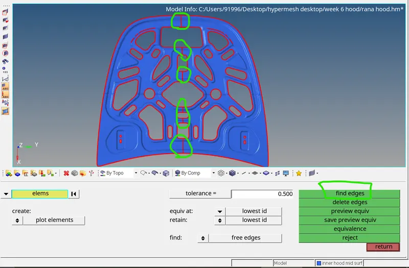
Finding edges on the mesh
- You can see that there are edges in the middle. Now delete all the edges.
- Again select all the edges and click on equivalence. This removes the edges present in the middle of the mesh.
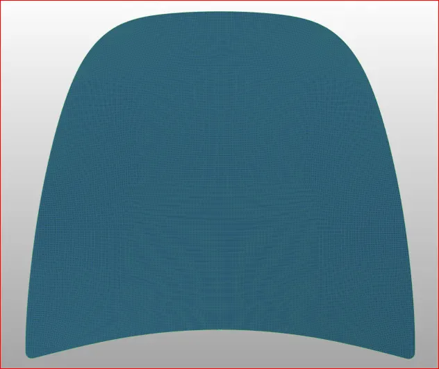
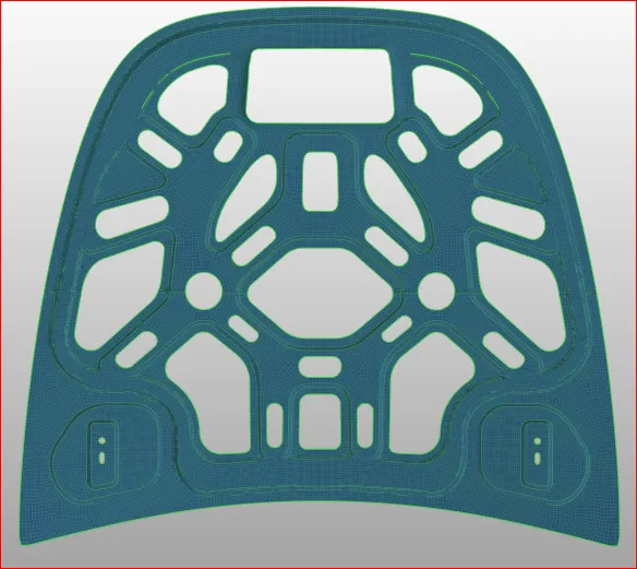
Upper hood,lower hood meshed according to quality parameters
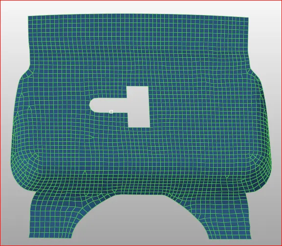
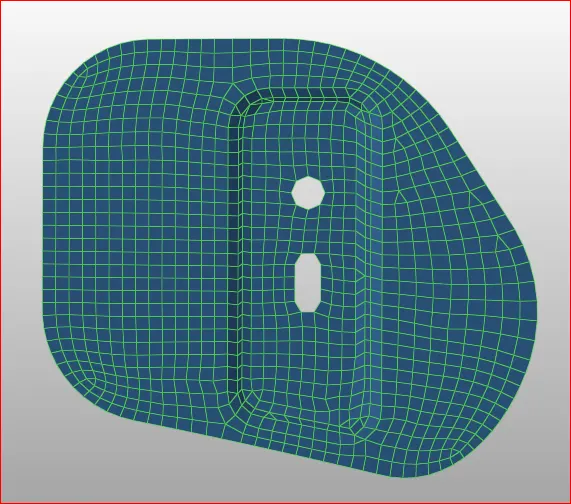
Latch & Hinge are meshed according to given quality parameters
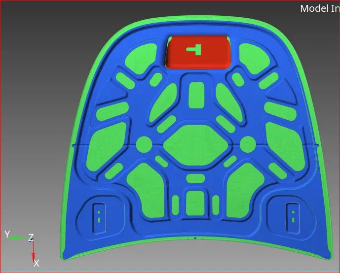
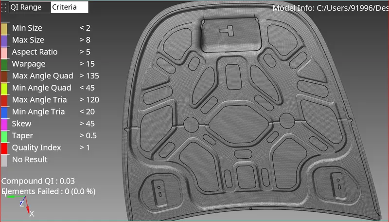
Hood meshed with no errors
Learning Outcomes:
- Able to do geometry clean-up with no errors.
- Able to generate mid surface for complex geometry.
- Aware of all the quality criterias and quality parameters during mesh generation.
- Understood about mesh generation and implemented mesh generation for complex geometry.
- Learned how to improve mesh flow and remove trias to achieve better mesh flow.
Conclusion:
After the completion, there are no quality issues found in the hood mesh. Mesh flow is good.