Week 6-Meshing of Hood Challenge
Aim
To mesh the given component with the size of 5 Units following the quality criteria with the 'Mixed' option to generate the mesh for crash & safety simulations using Hypermesh.
Procedure
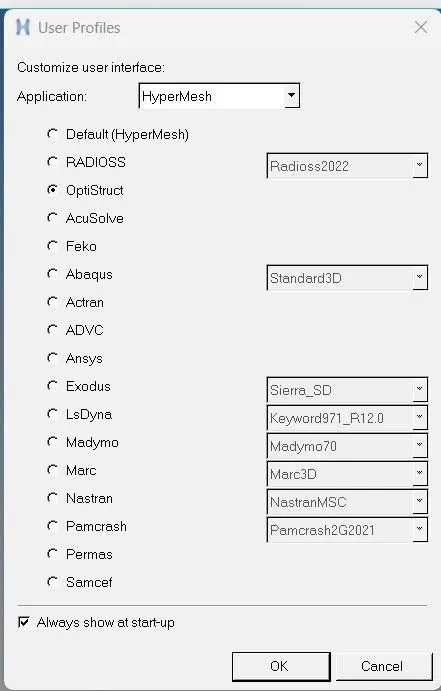
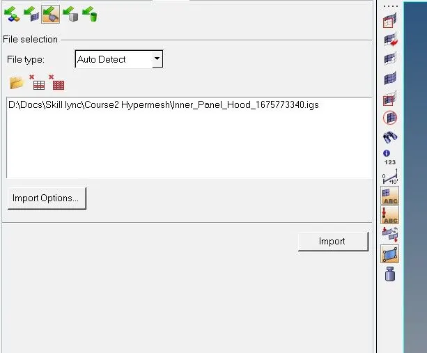
Imported the CAD geometry using the import geometry option on Hypermesh. As it supports the .igs file hence the challenge .iges file is successfully opened. Chose the optistruct profile to carry out the preprocessing.
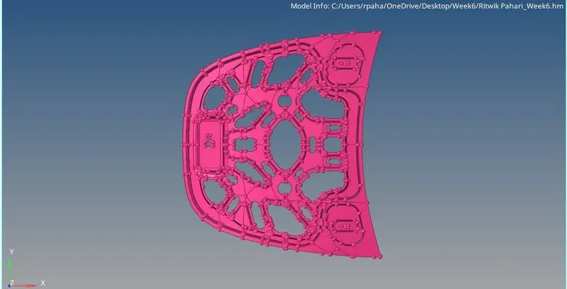
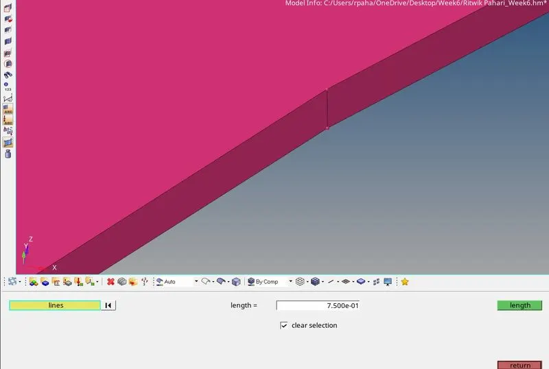
Measurements were taken for the sheet metal component (Inner hood panel)
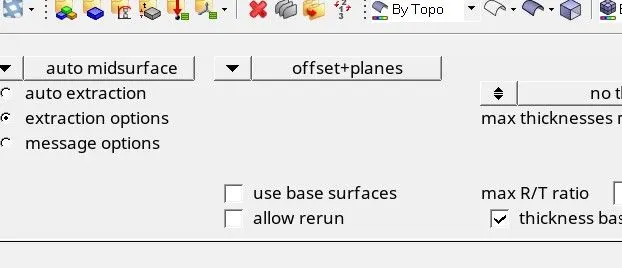
Before generating the midsurface at first performed the solid deletion on the component. Used delete option with solid selection then clicked on delete entity. Then used the Geometry>midsurface>automidsurface>extract option with extraction options as "offset+planes" to generate the midsurface.
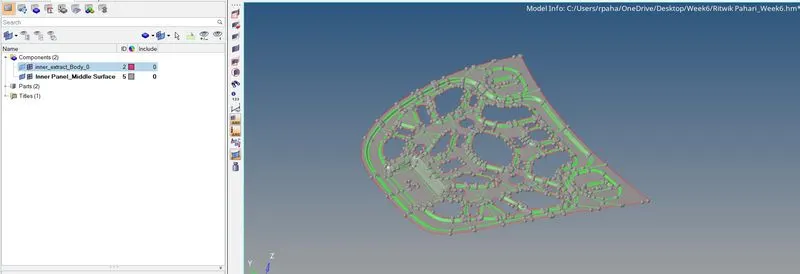
As the inner panel component is having surfaces which is identical so we can cut the surface into two equal part then delete one haif and work with another half. This will save a lot of time. For this at first used the quickedit>split with line to create a cut along the symmetry and then used the delete>surfs and deleted one half of the geometry.
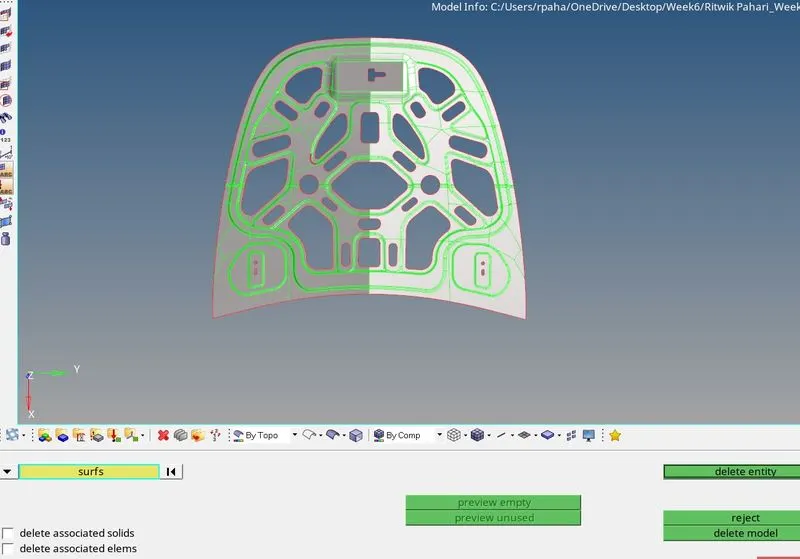
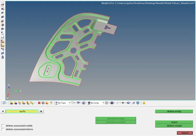
Geometry checkup for the whole component is performed using autocleanup by providing the target element size as 5 in both parameter settings and criteria settings. Sometimes this creates washer-splits on its own for the holes, but sometimes we have to do it manually. Used Quick edit>washer split with offset value as 5 to create the washer splits around the holes which were left without washer split during autocleanup. Also defeatured some of the fillet regions for better mesh flow (Geometry>Defeature>surface fillets>selected the lines making up the surface>find>remove). Also used toggle, split, supress, replace edge options wherever required especially while removing some of the construction lines and used spline command to generate missing surfaces or distorted surfaces.
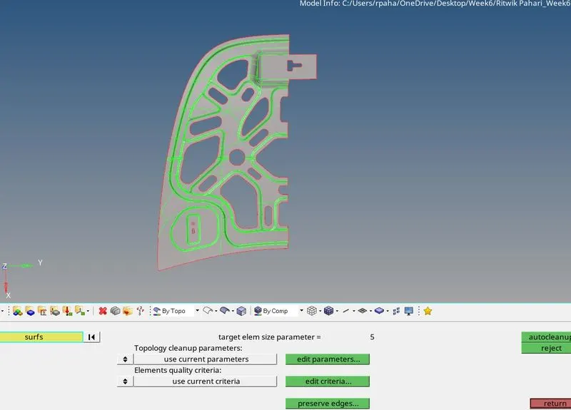
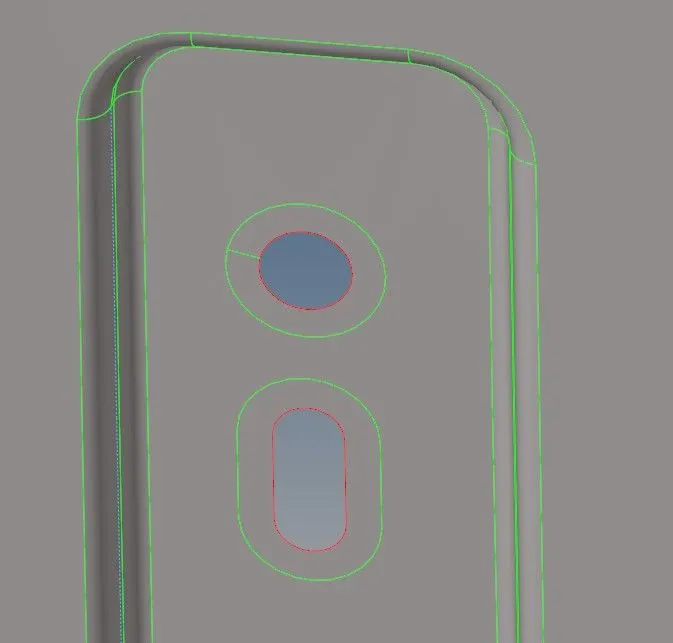
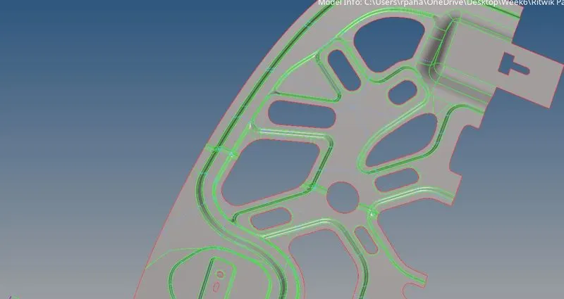
Now quality criteria is given in the question only which is as under:
Target Element Length = 5 Units
| S.N | Quality Criteria | Value |
| 1 | Aspect Ratio | 5 |
| 2 | Skewness | 45 |
| 3 | Warping | 15 |
| 4 | Taper | 0.5 |
| 5 | Min. Length | 2 Units |
| 6 | Max. Length | 8 Units |
| 7 | Min angle Quad | 45 |
| 8 | Max angle Quad | 135 |
| 9 | Min angle Tria | 20 |
| 10 | Max angle Tria | 120 |
| 10 | Tria % | 10 |
Now quality criteria is provided for quality checks so that the component is devoid of quality issues so that boundary conditions and loads can be applied further.
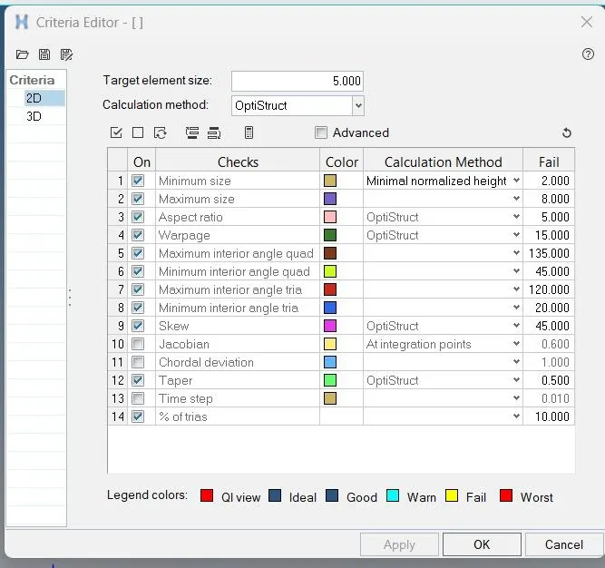
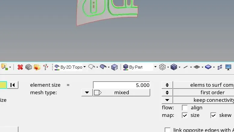
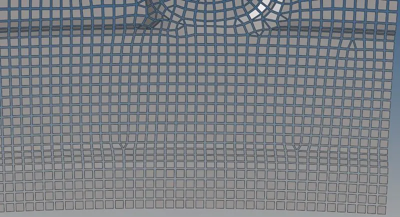
Then went to the 2D option and clicked on automesh. Given the element size as "5" units and selected the mesh type as "mixed", selected all the sufaces of the misurface using surfs>displayed and then meshed the component clicking on the mesh command.
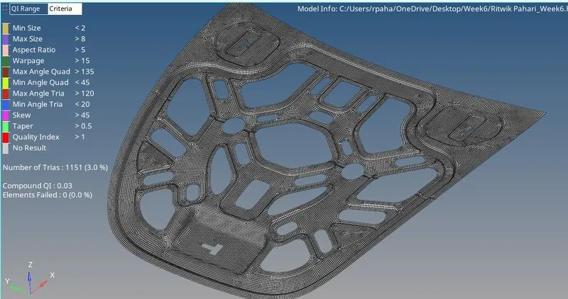
Used the automesh and rebuild mesh command to achieve better mesh flow, used qualityIndex>cleanuptools> drag tria element, Combine, Split, replace to remove trias at the edges and the boundaries and also used this to combine opposite trias using combine option in the element edit option. After all these, viewed the component "By Quality Criteria" and used the quality index with Fail as a threshold and cleared the failed element quality using the cleanup tools>Element optimize, Place node, Node optimize, Replace nodes etc.
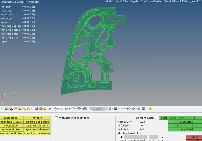
Also used Tools>Check elements and checked for all given quality criterias one by one and cleared the quality accordingly.

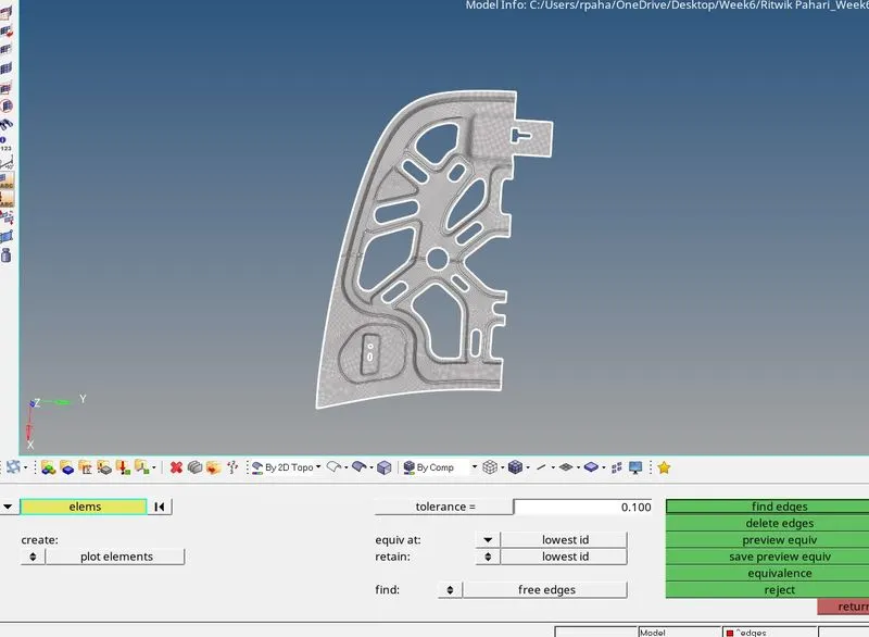
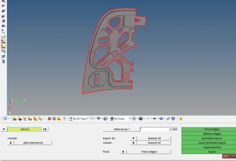
Then checked for the free edges using Tools>Edges>Elements>Displayed>Find Edges and checked for any cracks or edges in the bulk area where it should not be, by giving the tolerance values from 0.1, 0.2 to 2 (Min Element Size). As in this step I coudn't find any crackes and mis-attachment between the element edges, hence deleted the edges and proceeded to the next step.
After this checked for Dependency by Tools>Dependency .
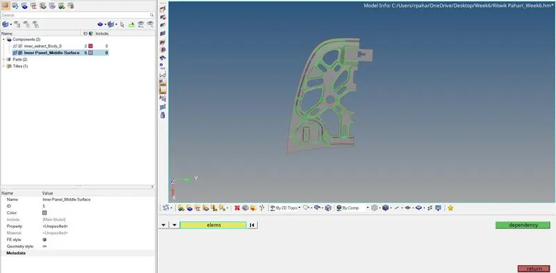
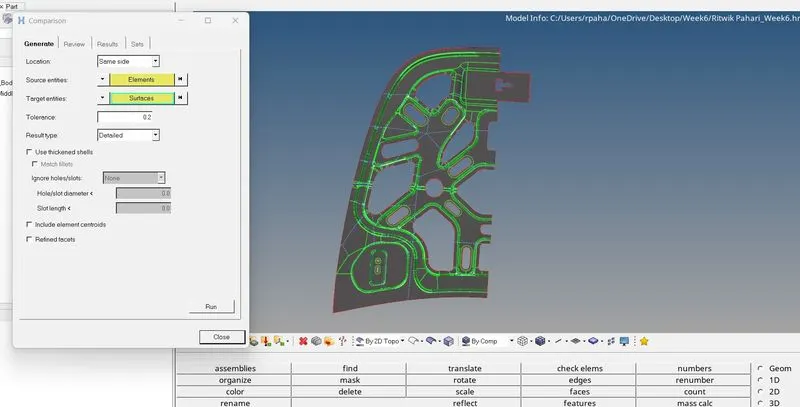
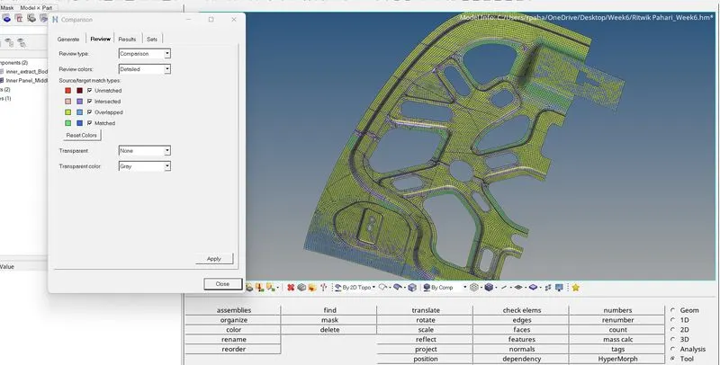
Then to check whether the FE elements has captured the geomerty or not, used Mesh>Check>Source-Elements-Displayed>target-surfaces-displayed>Run reviewed the results and for the red regions(unmatched) used project>to surface to project those unmatched elements to their respective surfaces.
Then checked for Intersections/Penetrations by using Tools>Penetrations>Elements-Displayed>check and then found no intersections/penetrations.
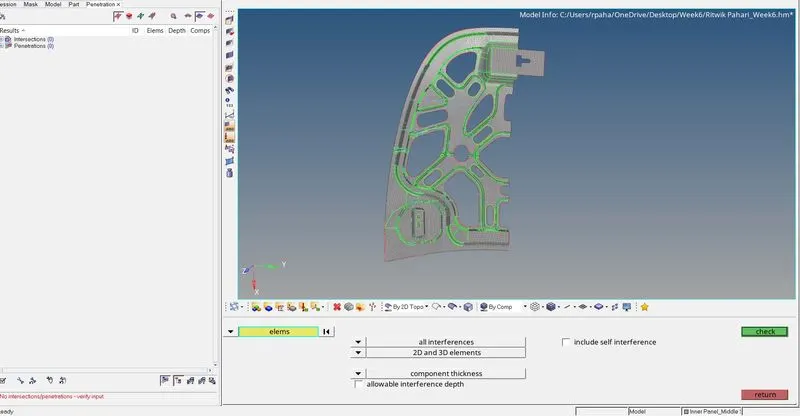
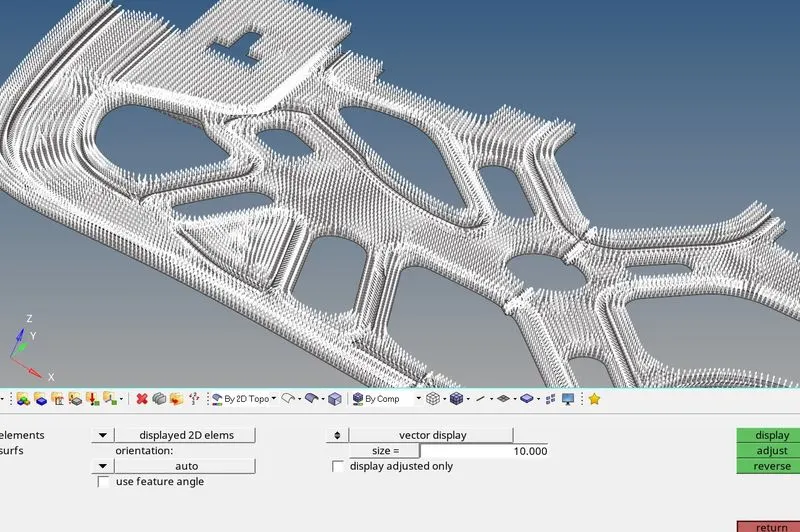
To check for normals used Tools>Normals>Display.
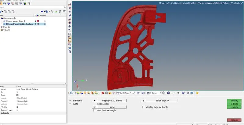
Identified the elements which were not oriented like all the other elements:
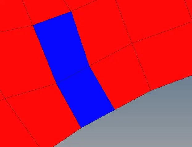
And rectified those elements:
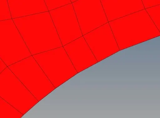
Also viewed the normals in vector representation:
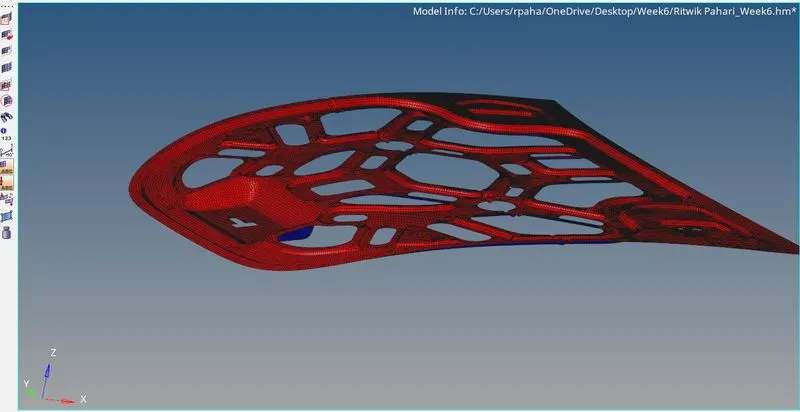
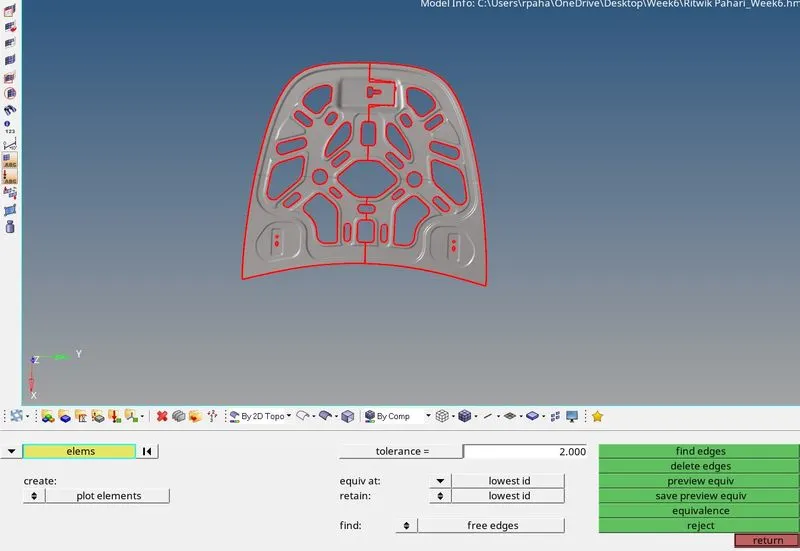
Before reflecting the elements at first the elements were duplicated. After this the identical parts are refleted to the other side by using Tool>Reflect>Elements-Displayed>Direction>base node>reflect. After reflecting to verify te connection between elements and if present then the connection should be established by finding the free edges, previewing equivalence and finally providing equivalence between the nodes respectively by using the Tool>Edges>Elements>Find edges>Elements>Preview Equivalence>Equivalence(Tolerance value between 0.1 to 2).
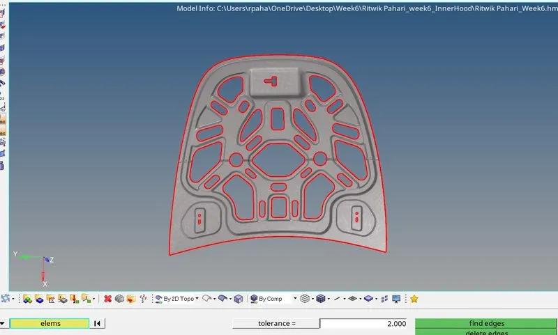
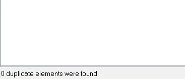
After this used Tool>Check elements>Duplicates>Save failed>mask-element retrieved>reverse>delete to find out the presence of duplicate elements and delete them respectively. Also used shrink element option to view duplicates if present.
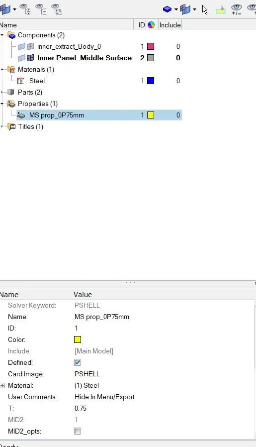
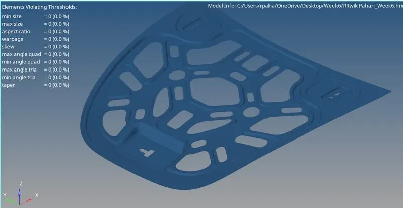
Created a property and material for the midsurface component and provided the thickness as 0.75mm and assigned the material and property to the midsurface component so that the component and mesh can be viewed with 2D detailed representation.
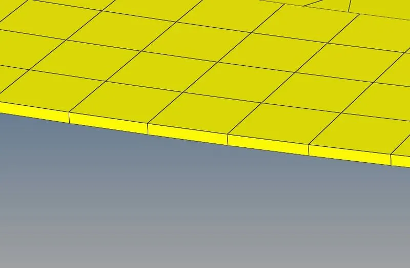
Viewed when "2D detailed element representation" option is turned on:
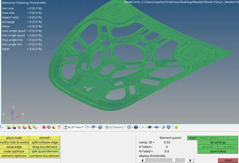
When viewed with quality criteria:
Learning Outcomes
At the end of this challenge I am more familiar with Hypermesh workflow, can perform cleanup, can generate mid surface, can perform defeaturing, can generate mesh with the given quality criteria.
Conclusion
Hence, the given component with target element length of 5 Units is meshed with the given quality criteria and mesh type using Hypermesh.