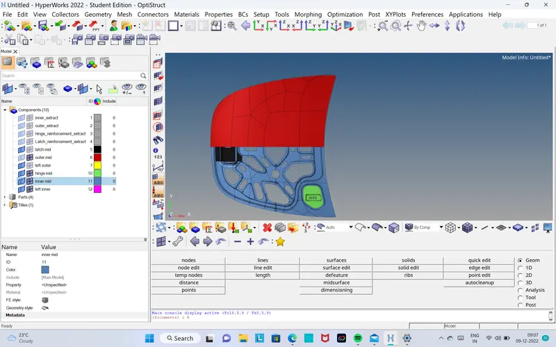
Week 6-Meshing of Hood Challenge
PREPROCESSING OF HOOD USING HYPERMESH Aim:
To extract mid-surface and generate mesh on Hood using Hyper mesh. Given Model: Steps Involved: Importing geometry and cleanup. Extracting Mid-surface and assigning properties. Meshing the surface with in the given quality criteria. Quality criteria: S. No…
Aim: To extract mid-surface and generate mesh on Hood using Hyper mesh.
Given Model:
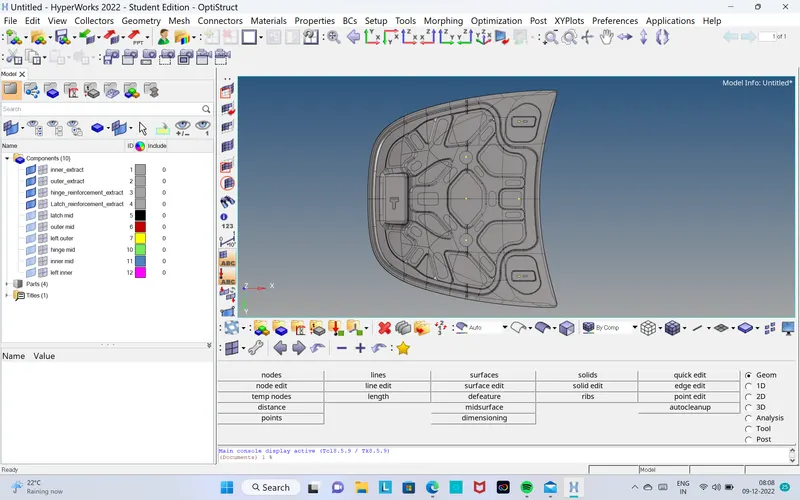
Steps Involved:
- Importing geometry and cleanup.
- Extracting Mid-surface and assigning properties.
- Meshing the surface with in the given quality criteria.
Quality criteria:
|
S. No |
Quality criteria |
Value |
|
1. |
Aspect ratio |
5 |
|
2. |
Skewness |
45 |
|
3. |
Warping |
15 |
|
4. |
Taper |
0.5 |
|
5. |
Min. Length |
2 |
|
6. |
Max. Length |
8 |
|
7. |
Min Quad Angle |
45 |
|
8. |
Max Quad Angle |
135 |
|
9. |
Min angle Tria |
20 |
|
10. |
Max angle Tria |
120 |
|
11. |
Tria % |
10 |
Procedure:
Step 1: Importing geometry and cleanup:
- To import the geometry, go to file >> Import >> select the file >> Import.
- After importing the geometry, the geometry is checked for any missing surfaces or triple cons. If there are no errors present in the geometry then the geometry is ready for the mid-surface extraction.
Step 2: Extracting mid-surface and assigning properties:
- Mid-surface can be extracted by any of the 4 methods below.
- Offset + plane + sweep.
- Offset + plane.
- offset
- Skin Offset.
- To extract the mid-surface, go to geom >> mid-surface >> select any extraction option >> select the surface >> extract. In this challenge offset + plane + sweep is used.
- After extracting the mid-surface, it is checked for any geometrical errors like needle faces, missing surfaces and triple cons. If any of the errors present then it should be rectified immediately.
- Now the properties like thickness, material etc. need to be assigned to the mid-surface. To assign the properties, select model in database and right click and choose create and then property.
- Now all the properties are entered in the property tab and the properties are assigned to the respective mid-surfaces.
- To assign the properties to mid-surface, right click on the mid-surface and then select assign and select the respective properties which needs to be assigned.
(1) LATCH MESH
- Hide the parent geometry
- Display only the latch component
IMAGE OF LATCH COMPONENT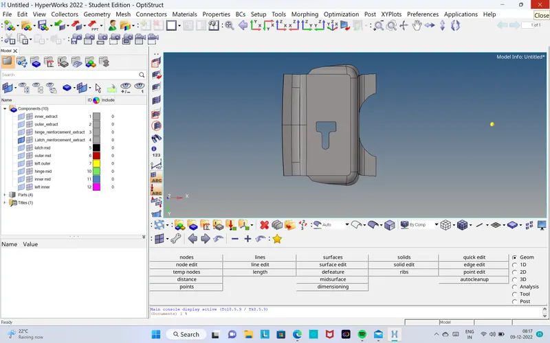
- After displayed the latch component,we have to delete the solid components.
- By using midsurface option ,create the midsurface by offset option.
- Clean up the geometry using autocleanup option.
- Then assign the quality criteria conditions as per given.
- Mesh the latch component with target element size of 5 units,and also the mesh should be in proper conditions.Suppose the mesh is not proper ,by using cleanup tools,rebuild mesh,element optimization,swag,these ara all the options play a main role in quality criteria.
FINAL IMAGE OF THE MESHED LATCH COMPONENT
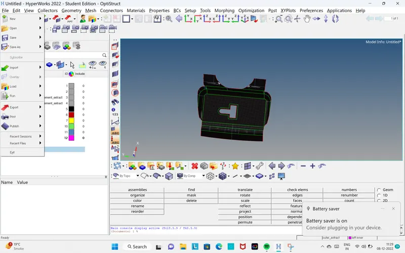
(2) HINGE COMPONENT
IMAGE OF HINGE COMPONENT
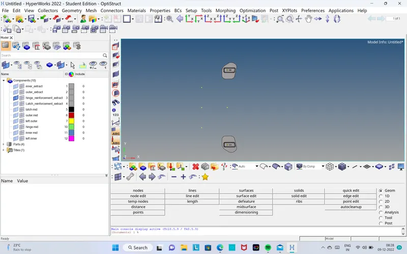
THINGS TO BE ACHIEVED FOR THIS TYPE OF SIMILAR COMPONENTS
- Delete the solid components.
- create the midsurface using midsurface option.
- Autocleanup the geometry.
- create the mesh as per the quality criteria conditions.
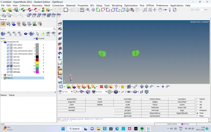
- To transfer the elements of the meshed component from left hinge to right hinge,use
(1) REFLECT option,for this we have to create the 1. Node
2. Distance option,create nodes between.
3. Reflect option,select the elements and duplicate .
4. assign direction into Y-axis with base node as node between the two nodes ,we get the same meshed element as per meshed previously.
MESHED HINGE COMPONENT
(3) INNER PART OF THE HOOD
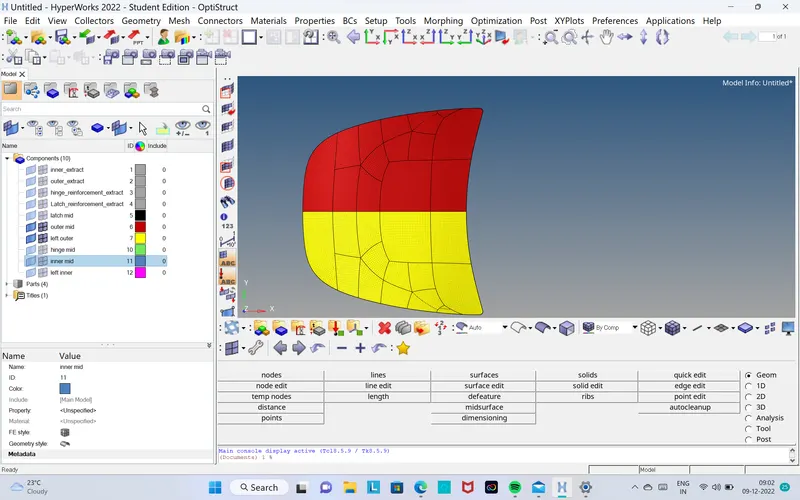
As we seen earlier,the same we have to do for this inner part.First we have to use ORGANIZE TOOL option(COLLECTOR),to divide the inner part into equally half.
(1) In geometry panel,QUICK EDIT OPTION,by using split surface by node option we can provide green lines for intersecting.
(2) create midsurface and autocleanup,then mesh it with required conditions as we did it earlier.
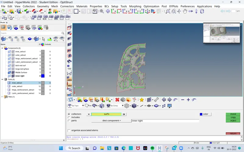
FINAL IMAGE OF MESHED INNER HOOD
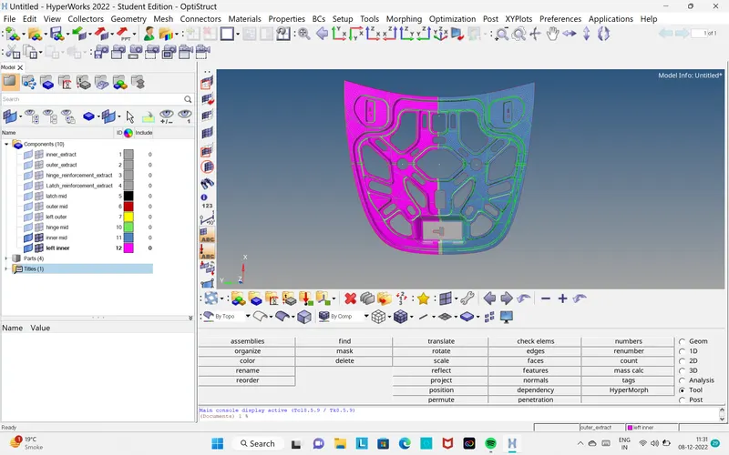
(4) OUTER PART OF THE HOOD
IMAGE OF THE OUTER PART OF HOOD
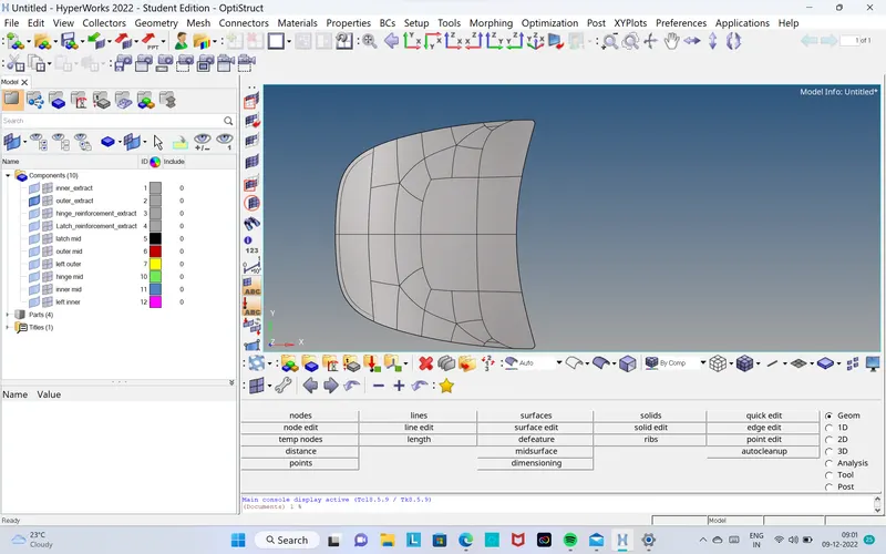
- The procedure is same as like we did for inner part
(1) organize option (collector)
(2) Reflect option,create node using line option in y axis direct,and assume base node as we did earlier.
MESHED PART OF OUTER HOOD
CONCLUSIONS
- For the given hood panel mid-surface is extracted and mesh is generated with in the given quality criteria.
THE FINAL IMAGE MODEL OF ALL MESHED HOOD COMPONENTS