Week 6-Meshing of Hood Challenge
AIM
For the given Hood model, Take the mid surface for all the components after checking the geometrical errors and mesh the mid surface with the given element Quality criteria.
Target Element Length = 5 Units
|
S.N |
Quality Criteria |
Value |
|
1 |
Aspect Ratio |
5 |
|
2 |
Skewness |
45 |
|
3 |
Warping |
15 |
|
4 |
Taper |
0.5 |
|
5 |
Min. Length |
2 Units |
|
6 |
Max. Length |
8 Units |
|
7 |
Min angle Quad |
45 |
|
8 |
Max angle Quad |
135 |
|
9 |
Min angle Tria |
20 |
|
10 |
Max angle Tria |
120 |
|
10 |
Tria % |
10 |
STEPS TO FOLLOW / PROCEDURES:
(Steps to follow in Short : Import Cad Geometry--> Perform Geometry clean -up-->Mid surface generation--> Perform Geometry clean -up -->Meshing the component with given element quality criteria-->Element Quality checks)
1] Import CAD Geometry
Import the model by using the "Import Geometry" option and select the IGES file, ensure all the components are available. There are 4 Components present in the Hood model:
- Latch
- Hinge
- Outer Body extract
- Inner Body extract
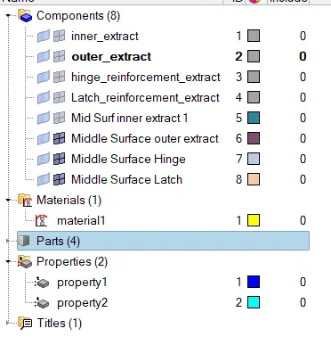
Final Image of Model Sessions
2] Geometry Clean up
Before Extracting the mid surface, if solids are available in the model are need to be deleted using the "Delete" Option by selecting Solids in it.
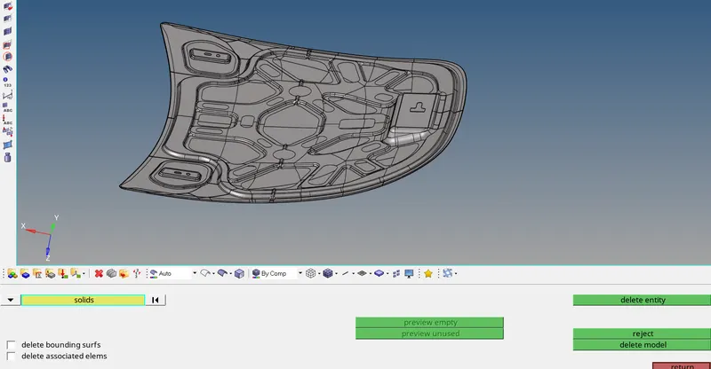
Deleting Solids frm Geometry
First step for any Geometrical error checkup is to perform a visual inspection of the model, In order to check the geometrical errors, switch Geometry visualization type to By Topo. All free edges are displayed in red colour and shared edges in green, T- junction edges in yellow and suppressed edges in blue.
In the next step we need to check for free edges and start filling missing surfaces
There are several options to fix the missing surfaces first option is to,
- Geometry -> Quick edit -> Filler surfaces, and select the free edge
- Go to Geometry -> Surfaces -> Ruled surfaces, select the first and second line lists and click create.
- Geometry -> Edge edit -> Replace, select the edge to be moved and edge to be retained also set the clean-up tolerance value and click replace.
4] Mid surface generation
To create a Mid surface on the component we have to choose " Geometry -> Mid surface -> Extraction options -> Offset + Planes".
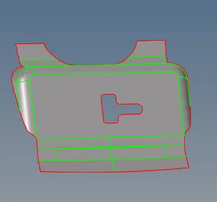
Mid surface
5] Perform Geometry clean -up
Now do the Geometry clean-up "manually" or by "Auto Clean-up" to clear up the unwanted Line in the geometry in it.
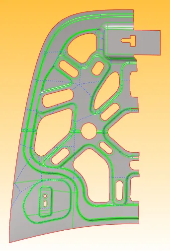
Mid surface (only half is taken due to symmetry)
To clean the Components manually use the Quick edit panel by pressing F11, Using "Toggle" un split the unwanted line in it. Once the Clean-up is done, Now it's time to Create a Mesh on the mid Surfaces. The toggle edge tool is used to suppress unwanted edges as shown in the picture below. The dotted blue line is suppressed so that a proper mesh can be achieved.
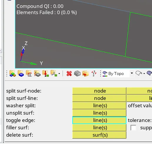
Toggle Edge
To remove unwanted points the add/remove point and the replace point tools are used. To use the add/remove point tool, the point that has to be removed is right-clicked and if we want to add a point a left click is done. To use the replace point tool, the point that has to be replaced is selected first followed by the point that will be retained
When there are holes in the surface a washer split is added so that the surface can be better captured when meshed.
6] Meshing the component with given element quality criteria
To do Mesh on the Component " 2D -> Auto mesh -> Select the area to be mesh "
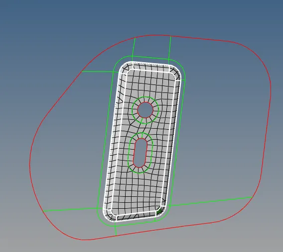
Meshing by Discretizing into small rectangles
The element size is changed to 5 and the mesh type is chosen as mixed and the surface to mesh is selected. The meshing of the surface is done in batches so that proper changes in the number of nodes and quality checks can be done with much less difficulty. When meshing if a tria element is formed it can be removed by either increasing or decreasing the number of nodes under normal circumstances when the surface doesn't have extreme curves.
In some cases when a proper mesh is not attained in such that case we can use "Remesh" Option so that instead of remeshing the whole components by using the "Remesh" option we can built a good mesh flow by the selecting the region that has to be meshed.
The elements are selected in a way that they form either a square or a rectangle or any closed figure so that a better mesh can be obtained. We can change the element density by increasing or decreasing the number of nodes, left mouse click to increase and right mouse click to decrease.
Due to the component which is shown above is symmetry we can construct half of the geometry for meshing and then using an auto mesh option the mesh can be created. To reflect the component once the meshing is done to the model "Tool -> Reflect -> Select Elements -> Duplicate -> choose the base point" before that make the model as the current component or else the main components will get reflected it.
In order to give connectivity between reflected parts, go to Tools -> edges -> select the component -> give tolerance value -> select preview equivalence - > equivalence
7] Element Quality checks
After re-meshing, to improve and check the quality of the mesh the 'quality index' tool in the 2D tab is used. Elements that are highlighted in colours are not acceptable and have to be rectified.
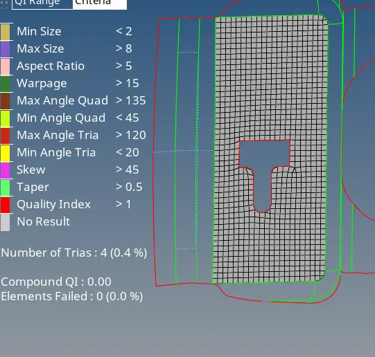
Quality checks
After all the elements in colours are rectified by using the clean up tools or by re-meshing, the 'check elements' tool under the Tool tab is used to check the elements for all the quality criteria individually.
8] Giving Thickness to the shell elements
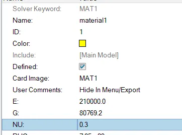
Material Card
In order to give thickness to the shell elements we need to create a property card and material card. Then the thickness is given to the component property and assign the property to the mid-surface component and change visibility to 2D detailed element representation.
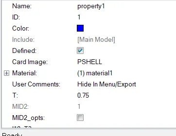
Property Card
Result:
The given component are meshed along with the given quality criteria, and the quality of the meshes has been checked by using quality checks.
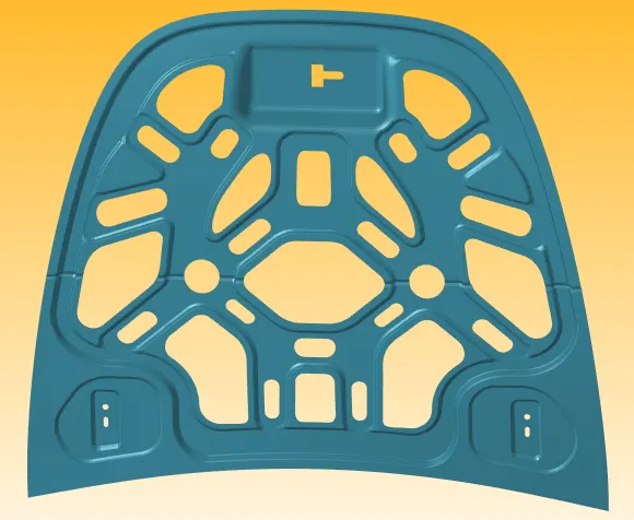
Final Drawing of Inner Extract
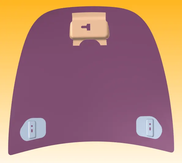
Final Drawing of Outer Extract, Hinges & Latch