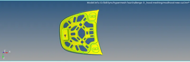
2-D Meshing of an automobile's hood.
Objective: To perform 2d meshing of a car's hood as per the given quality criteria.
Given:
a) Step model of the required component.
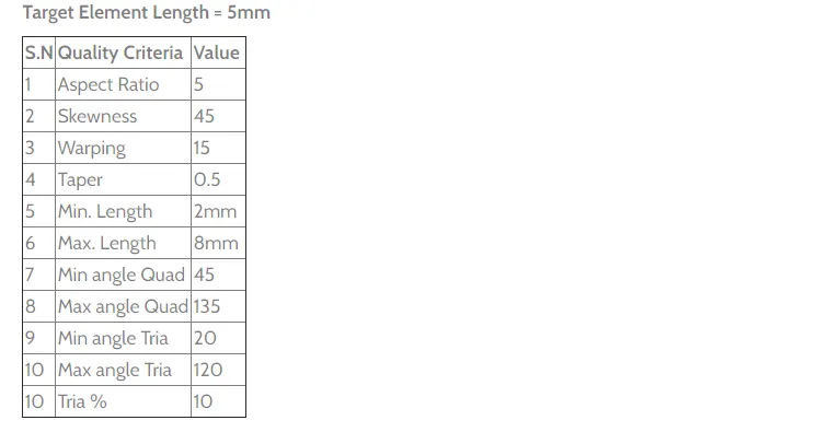
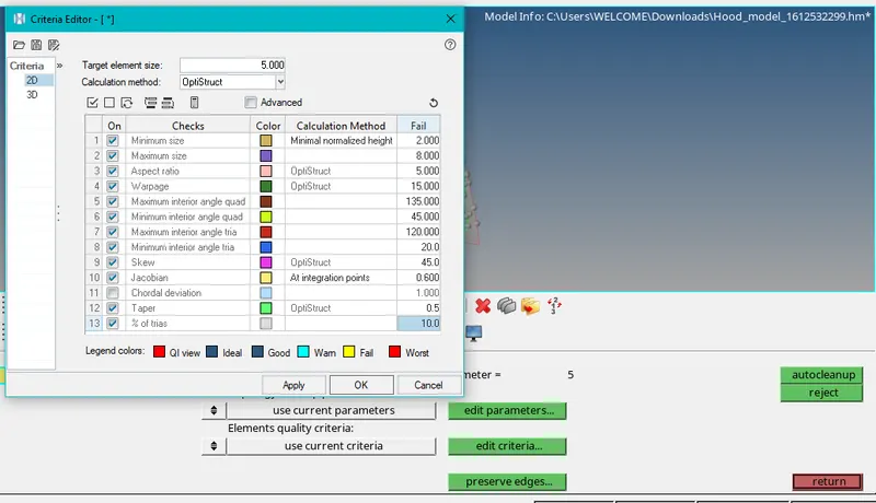
b) Required Quality criteria :
Procedure:
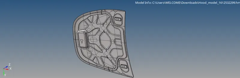
1) Import the step model into HyperWorks using the 'import geometry' command.
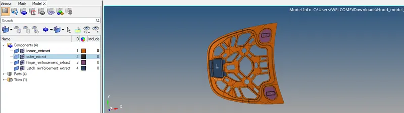
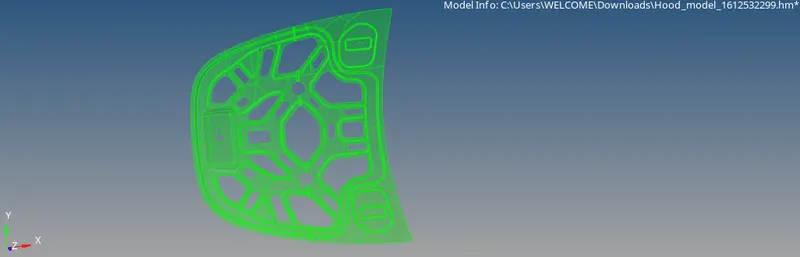
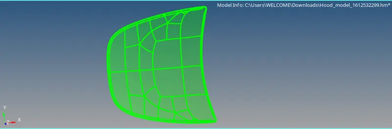
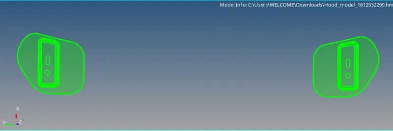
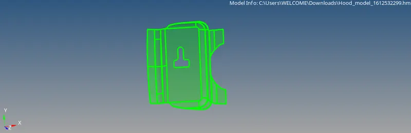
2)The hood geometry has four different components :
a) Inner extract b) Outer extract
c)Hinge extract d) Latch extract
3) Now before extracting the mid-surface check for any geometry errors in each component by changing the display mode to by-topo and check for any missing surface, free edges, and duplicate surfaces. After thorough checking, no such errors were found in the parent geometry and the model is good to go for mid-surface extraction.
a) Inner extract
b) Outer extract
c)Hinge extract
d) Latch extract
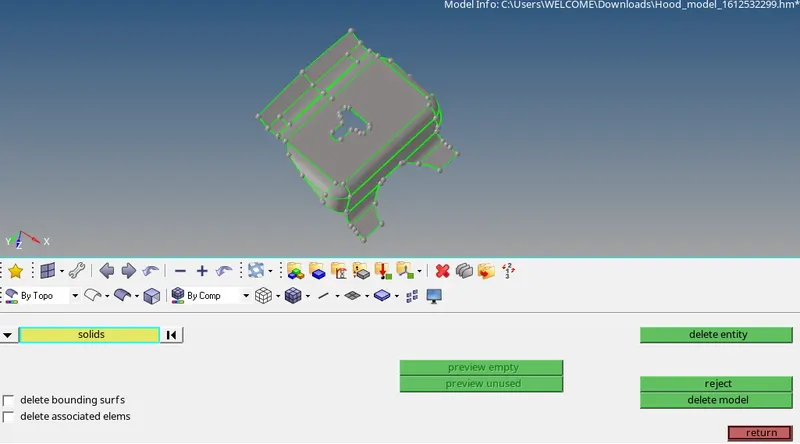
4) Now before creating the mid surface make sure all the solid are deleted from the model by using the 'delete' option.
I---->LATCH EXTRACT
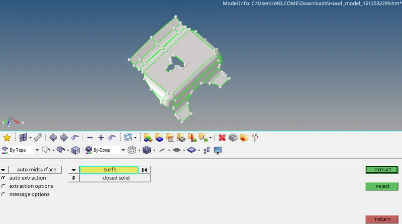
5) Now create a mid-surface, so that the entire 3D geometry can be represented as a surface which will reduce the computational time and storage for carrying out the task. For incorporating this, select the 'midsurface' option and select the upper bracket surface for the mid-surface creation. Now select 'extraction option' and then select 'skin offset' which ensures a proper midplane generation with all the fillets and curves. Now click the auto extraction option and select create for the same.
6)After extracting the mid-surface, check for any errors in the mid-surface in the form of missing surfaces, duplicate surfaces, or free edges.
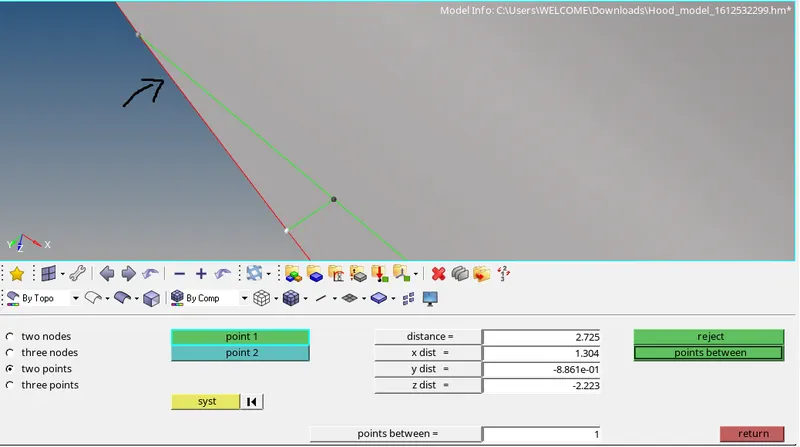
7) Instead of performing auto cleanup which can distort the geometry, try to manually clean up the mid-surface by toggling the edges where the mesh elements would fail and rectify other errors. For toggling edge, measure the distance between two edges and if it less than min element size then create a split before the reduced dimension and toggle the edge following that split line.
a) Step-1
b) Step-2
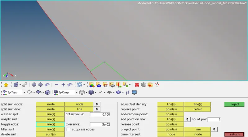
8) Delete unnecessary points if present.
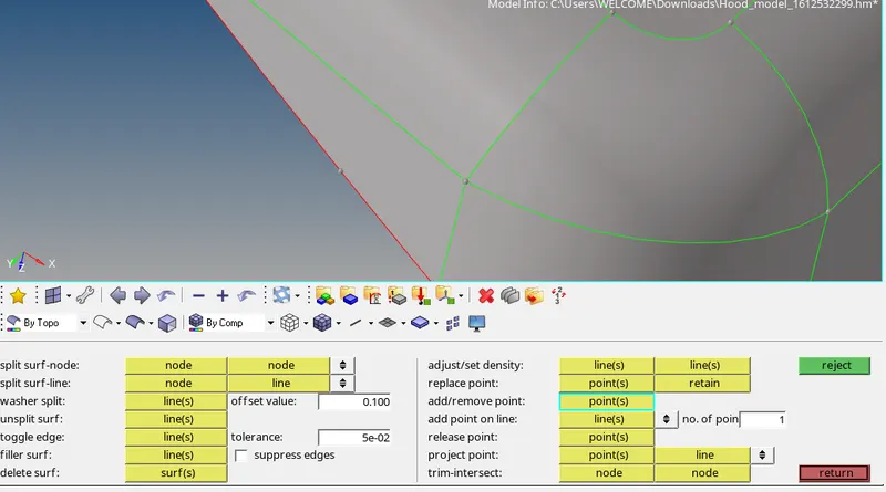
9)Now through the geometric clean-up process, all the missing surfaces have been created the model is free from and free edges. To cross-check for any leftover errors and free edges change the mode of the display to wireframe mode and check for any free edges which are marked by the presence of any red lines. If all the lines displayed are green, then it means the model is free of free edges.
10) Before creating the mesh mention the quality criteria required in the 'criteria fil settings' from the 'preferences' tab.
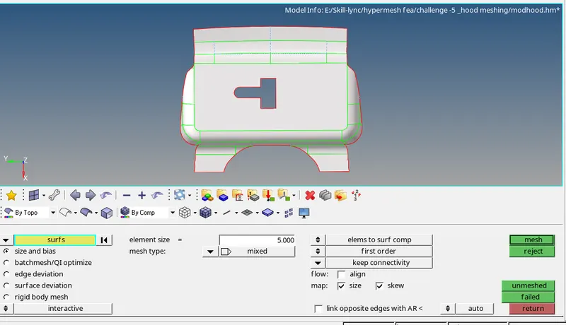
11)Now click '2d' option and select the 'automesh' option. Select all the surfaces and set the 'element size' as 5 mm which is the target element size and select the 'mesh types' of mixed. The reason behind choosing mixed mesh type over quads is mixed elements ensure proper mesh flow and avoids the formation of rotational quads.
12) Now try to minimize the number of trias present in the mesh by adjusting the number of nodes along the free edges and try to obtain a proper mesh flow.
Step-1 improper mesh with trias
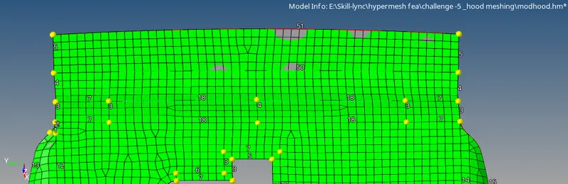
step-2 align the nodes to get a proper mesh flow and to minimize the triangular elements present.
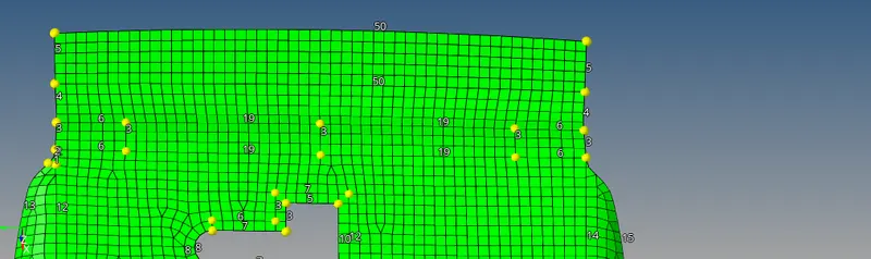
step-3 To remove trias we can select oppositely oriented trial elements and mesh it again to obtain an optimized mesh without trias.
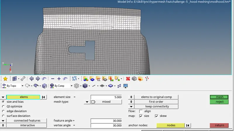
step-4 To try out different combinations of nodes combination along the edge to obtain near to perfect mesh.
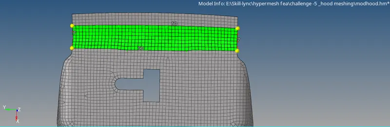
step-5 we can also use the node alignment option to align all the elements in a straight line in accordance with the pattern.
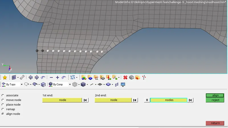
step-6 we can use the smooth option to get a proper alignment and spacing between the elements.
13) Now we have to check the quality of the mesh in order to ensure that the mesh won't fail during analysis. For that click on 'quality index' and set the display threshold to 'worse'.This displays all the elements( in red or yellow colour) which will definitely fail during analysis. Now click on 'cleanup tools' and select the 'place node' option and try to arrange the colored elements in such a way that they won't fail. This can be assured when the elements discolor after properly placing the nodes.
note: we can also use the element optimization tool for this.
figure-1
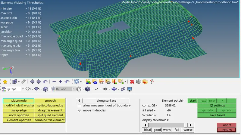
figure-2
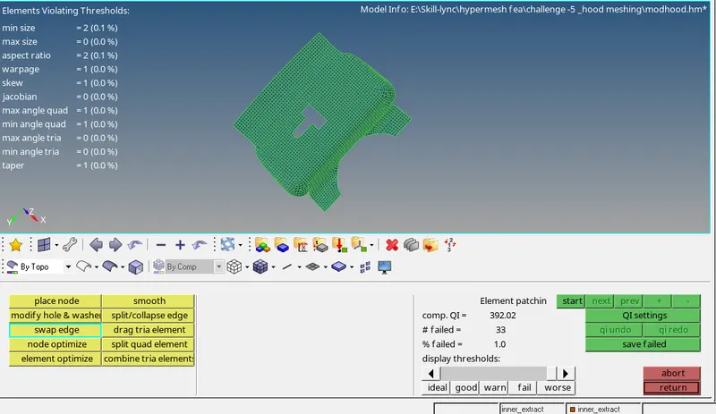
14) Repeat the same process after setting the display threshold to 'Fail'.
15) Now once all the elements have met the criteria reconfirm it by checking all the elements for each quality criteria by using the 'check elements' command. In this particular case, all the criteria are matching.
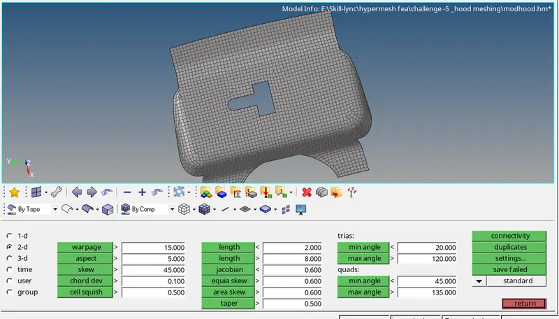
16) Now check for any free edges present in the model by using the 'edge' option in the 'tool' command. In this particular case, there are no intermediate free edges found and hence the mesh and the model are good to go.
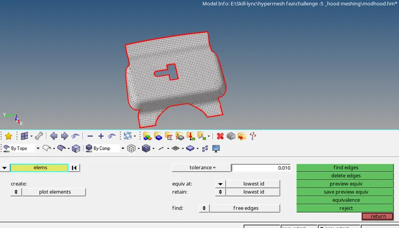
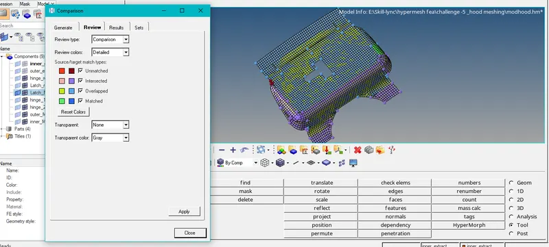
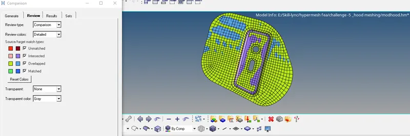
17) After this, we can check how well the mesh elements have captured the surface of the model by 'mesh' > 'check' > 'elements' >'comparison command.
Step-1
Select the elements and surface that have to be compared and give an appropriate tolerance value. Once the command has been successfully compiled a pictorial representation of good captured and poorly captured(red color) regions would be displayed.
Step-2
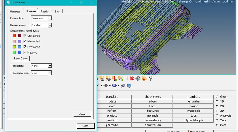
Project the poorly captured elements to the surface of the model to get a more appropriate mesh and then re-mesh that particular region to get a smooth mesh flow.
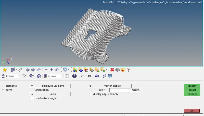
18) Once done with this we can check for the normality of the surface plane of the model by selecting the 'Tool'> 'normals'.If the normals are perpendicular and on the same side of the surface that means the model has the right normality for the surfaces of the model.
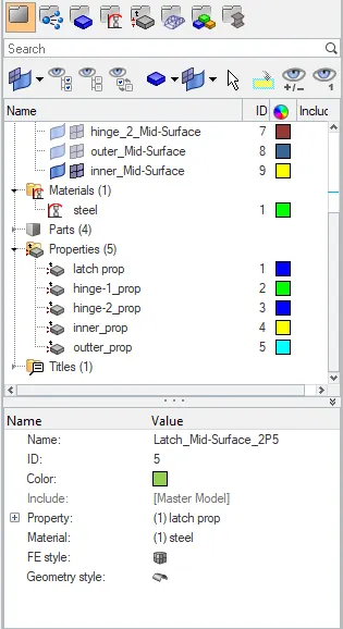
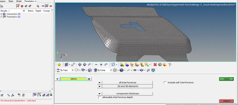
19) We can also check for any penetration among the mesh elements or surfaces by using the 'penetration' command. But for that first, we have to assign material and property(thickness) to the mid-surface.In this particular case, the model is free from any kind of penetrating elements as mentioned in the status bar.
Step-1 Assigning the material and property(thickness) to the component.
Step-2 check for any penetrating elements.
20)
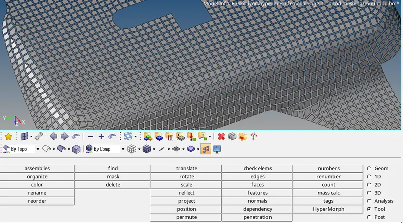
a) At last we can check for any duplicates mesh elements by using the ' shrink element' command. This particular model is free from any duplicate mesh elements.
b) Optimized mesh
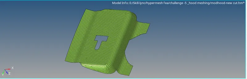
21) We can follow the same method for hinge extract, inner extract, and outer extract.
II----> HINGE EXTRACT
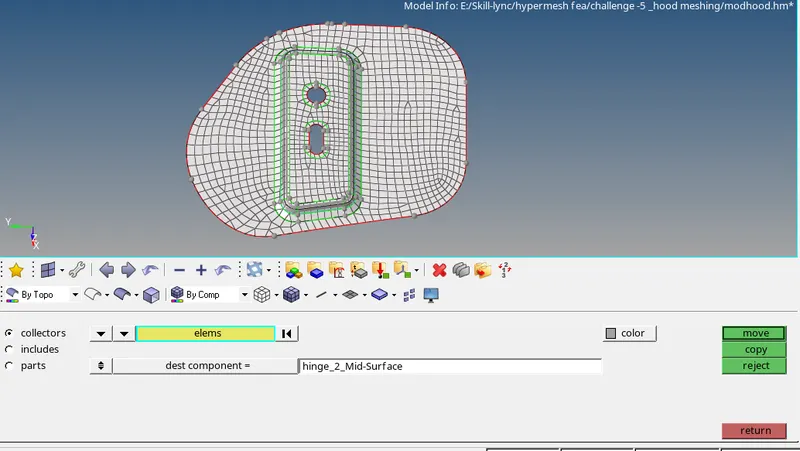
22) For hinge extract separate mid-surface has to be created for each of the two extracts. So as both the hinge extracts are symmetric we can just create a single mid-surface and mesh it and then reflect it on the other side.
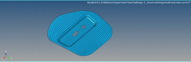
a) Mid-surface with mesh elements:-
b) Mesh criteria check:-
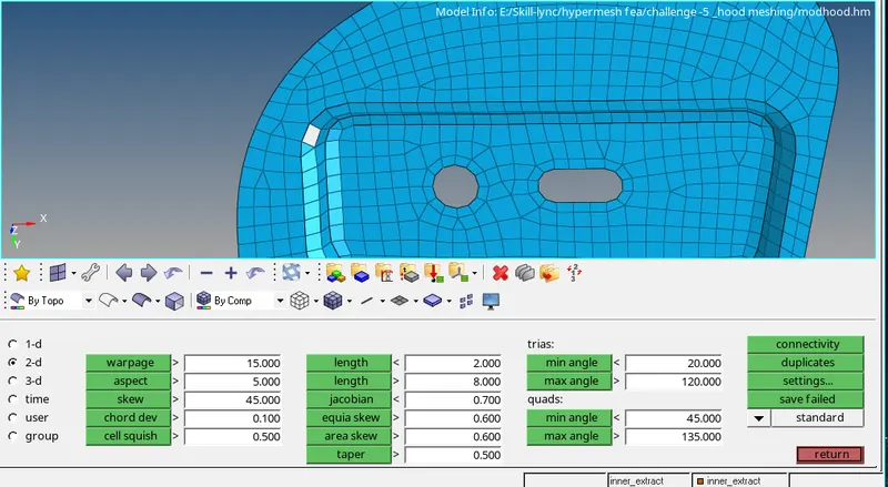
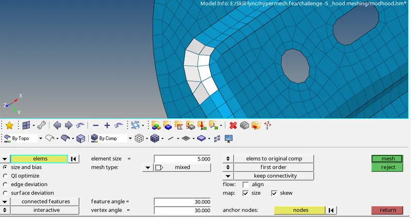
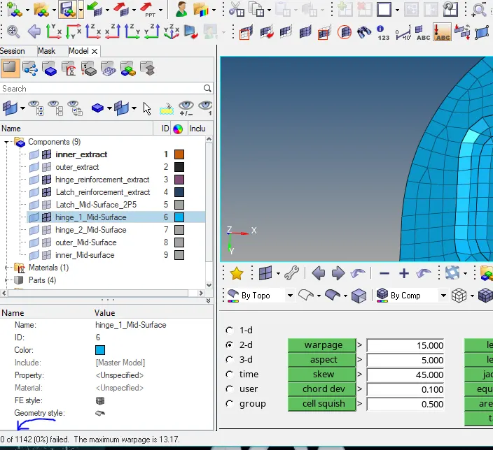
In the hinge extract, there is a mesh element with a warpage error. Now if a lot of elements are failing for this particular error we could save all the failed elements reverse mask them to easily identify them. But as in this case, only one element is failing we can easily identify it and remesh it or use the quality index command to rectify the warpage issue.
step-1(finding the failed element)
step-2(remeshing)
step-3(Warpage corrected)
c) The extent of surface capture by the elements:-
d) Optimized mesh
e) reflect the mesh and elements and save them as hinge extract 2.
step-1(surface reflection)
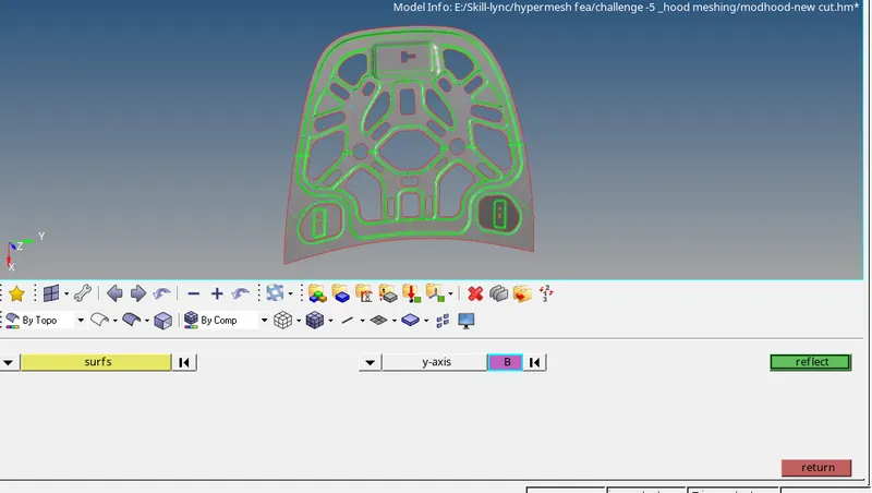
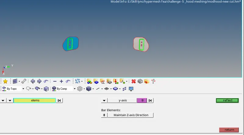
step-2(mesh reflection)
After reflecting the mesh elements and surface use the organize command to move the reflected mesh and surface to the part named hinge -2.
Note: - before reflecting the mesh, change topology revision to keep mesh so that the alignment of the existing mesh is not messed up when integrated with the reflected mesh.
III----> OUTER EXTRACT
23) As the outer extract is a symmetric model we can delete the half portion of the created mid-surface and then perform geometric clean p followed by meshing in accordance with the quality criteria.
a) Initial Midsurface:-
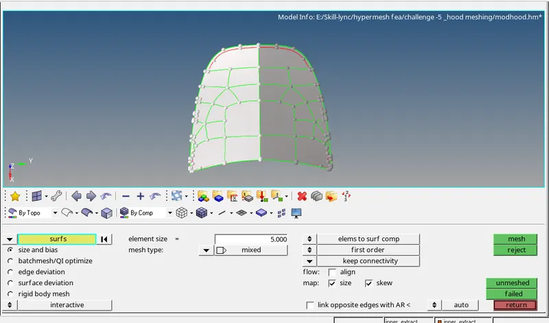
b) After deleting the half portion of the mid-surface we perform geometric clean-up and divide the mid-surface into proper regions for meshing by using split lines.
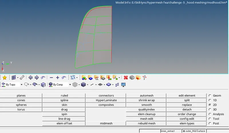
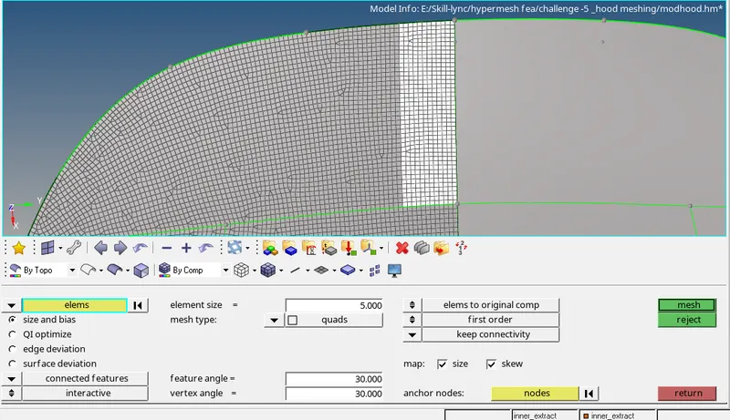
c) Meshing and rebuilding:-
note:-use a single layer of elements in the hemming region.
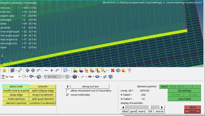
d) Quality Index:-(Except for the hemming region there shouldn't be any failing elements.)
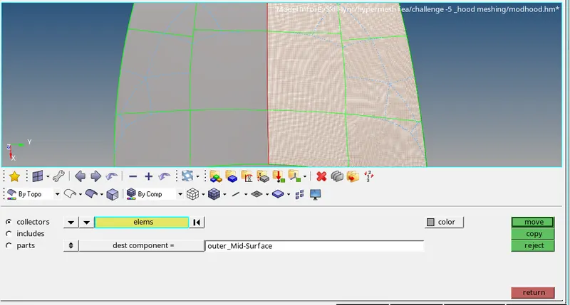
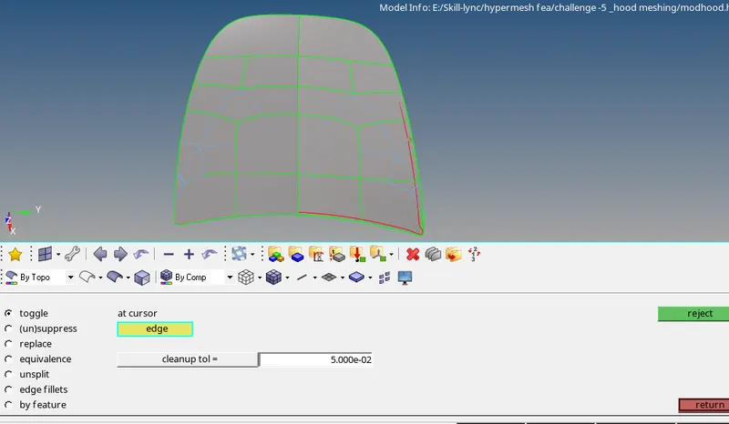
e) Once done with the mesh reflect the surface for getting the complete model and before reflecting the mesh make sure to change the topology revision to keep mesh so that the alignment of the existing mesh is not messed up when integrated with the reflected mesh.
Step-1( topology revision)
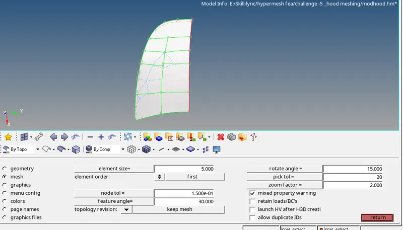
Step-2(reflect)
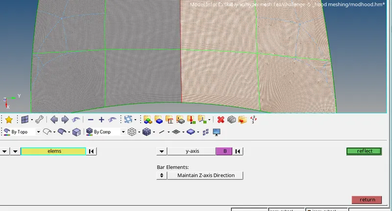
Step-3 (Move the elements and surface by using organize command)
step-4 (toggle the line of reflection)
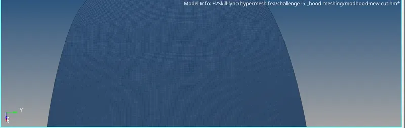
f)Optimized mesh
IV----> INNER EXTRACT
24) Inner extract is also symmetric and hence we can just mesh half of the portion and reflect the rest.
a) Create the midsurface and delete the half portion and start meshing the remaining half. Mesh one region at a time and then proceed to the following.
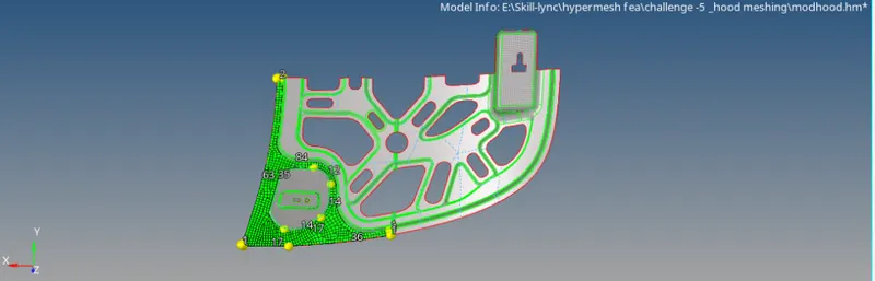
b) After meshing check the quality of the created mesh using quality index.
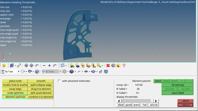
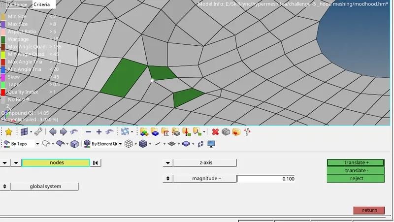
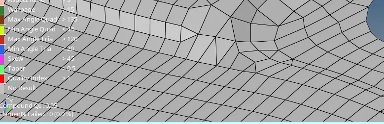
c) If the elements fail for warpage and the error is not being rectified after remeshing or by using the element optimization method, then we can use the translate command to orient and position the node in such a way so that the warpage error is rectified. For this change the display mode to ' by element quality' and use the 'translate command to strategically place the node of the failing element.
Before translating the node:-
After translating the node:-
note:- when the warpage angle deviated from the prescribed by a great extent then we have the split the elements into trias for rectifying the error.
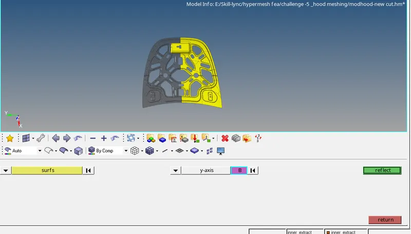
d)After this reflect the mesh and surface as mentioned in the above steps and use organize command to move the reflected entities to the original part:-
step-1(reflecting surface)
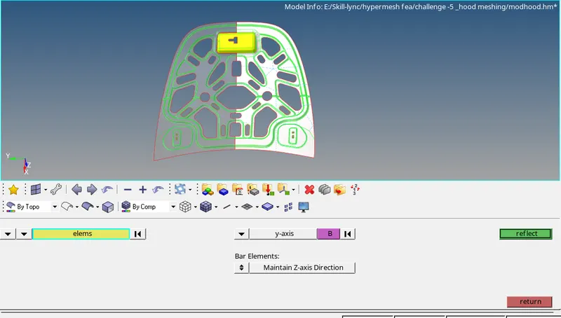
step-2(reflecting the elements)
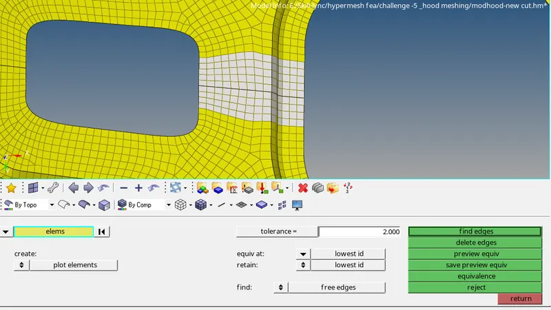
e) use the equivalence command to remove the line of reflection and to maintain the connectivity of the elements after toggling the free edge along which the reflection has been done.
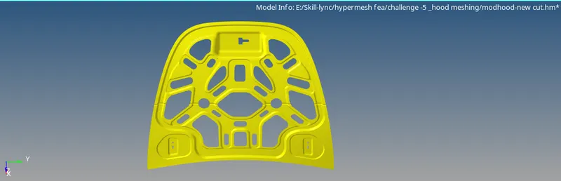
f) Optimized mesh
Results & Final model :
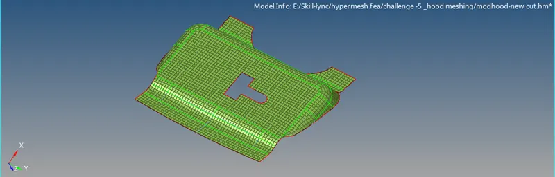
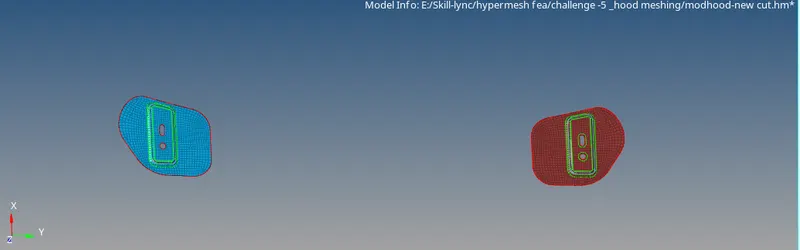
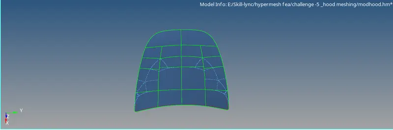
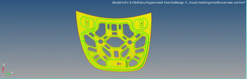
The components have been meshed in accordance with the given quality criteria and the appropriate thickness has been assigned to the components.
Latch:-
Hinge:-
outer extract:-
Inner extract:-
Combined Hood:-